1.01 SECTION INCLUDES
A. Portland Cement Concrete (PCC) Pavement.
B. Portland Cement Concrete (PCC) Pavement Widening.
C. Portland Cement Concrete (PCC) Curbs and Gutters.
D. Portland Cement Concrete (PCC) Resurfacing.
1.02 DESCRIPTION OF WORK
A. Includes the requirements for the construction of full depth Portland Cement
Concrete (PCC) pavement, pavement widening, and concrete curbs and gutters placed
upon a prepared or corrected subgrade or previously constructed base or subbase. See
Division 2 - Earthwork and
Site Grading for subgrade and subbase construction specifications. This section shall
also include final subgrade/subbase preparation for concrete paving.
B. Includes the requirements for construction of the following PCC Resurfacing applications:
1. PCC bonded overlay placed directly on an existing full depth concrete pavement
2. PCC unbonded overlay placed on a stress relief course (bond breaker) over an existing
PCC pavement or and existing PCC pavement that has been overlaid with HMA (composite pavement).
3. Whitetopping / PCC overlay placed directly on an existing full depth asphalt pavement.
C. Reference is made to the Iowa Department of Transportation Standard Specifications for
Highway and Bridge Construction, Series 2001, and all current General Supplemental Specifications
and Materials Instructional Memorandum by the term “Iowa DOT Specifications” and/or “Iowa DOT I.M.”
D. The work shall include all labor, equipment, and materials necessary to complete the paving
as specified in the contract documents.
1.03 SUBMITTALS
A. Submit under provisions of Division 1.
B. PCC Mix Design: Mixes are Class C, M, C-V47B, and M-V as defined in Iowa
DOT 2301 and I.M.
529. Unless otherwise specified in the contract documents, maturity method for strength
determination prior to opening to traffic will be allowed. Class A shall be used for concrete
base or temporary pavement and recreational trails only. Class B shall be used for temporary
pavement and recreational trails only. After October 31 all Class B concrete will be replaced
with Class A concrete. In cases where early opening of pavement is desirable, the contract
documents may require the use of Class M, or M-V concrete mixtures or may require using Type
III cement with other concrete mixtures. Such sections of pavement may be opened to traffic
in accordance with the limitations of Section 7010, 1.07.I.
1. Two weeks prior to commencing any Portland concrete placement, the Contractor shall
submit a paving mix design for each different source of aggregate to be used for review
and approval by the Jurisdictional Engineer. Mixes or mix designs approved by the Iowa
Department of Transportation or an independent testing laboratory shall be submitted.
2. Submit all testing and certifications in accordance with Section 7010,
3.14.
C. Upon requests the Contractor will provide Material Certifications to the Jurisdictional Engineer.
1.04 SUBSTITUTIONS
A. Use only materials conforming to these specifications unless permitted otherwise by
Jurisdictional Engineer and shown in the contract documents.
B. Obtain approval of Jurisdictional Engineer for all substitutions prior to use.
1.05 DELIVERY, STORAGE, HANDLING, AND SALVAGING
A. Aggregate Storage: Prevent contamination and frequent variations in specific gravity,
gradation, or moisture content; Iowa DOT 2301.
B. Concrete transported without continuous agitation shall not be used if the period elapsed
between the time the concrete is mixed and the time it is placed is greater than 30 minutes;
Iowa DOT 2301. With the approval of the Jurisdictional
Engineer, an approved retarding admixture may be used at the rate prescribed in Materials
I.M. 403 and the mixed-to-placed time may be extended
by an additional 30 minutes.
C. Concrete transported with agitation shall not be used when the cement has been in contact
with the aggregate more than 90 minutes before it is placed;
Iowa DOT 2301. With the approval of the Jurisdictional Engineer, an approved retarding admixture
may be used at the rate prescribed in Materials I.M. 403.
D. Concrete containing Type III cement and transported with agitation shall be delivered and
placed within the following time limits:
Concrete Temperature
(at time of
mixing, degrees F) |
Maximum Time
(from mixing to placement, in min.) |
| 75 or less |
60 |
| 76 to 85 |
45 |
| above 85 |
30 |
E. The methods of delivering and handling the concrete shall be such that objectionable
segregation or damage to the concrete will not occur, and that which will facilitate placing
with a minimum of rehandling; Iowa DOT 2301.
F. The compartment in which concrete is transported to the work shall be thoroughly
cleaned and flushed with water to ensure that hardened concrete will not accumulate.
Flushing water shall be discharged from the compartment before it is charged with the
next batch; Iowa DOT 2301.
G. Cement and Fly Ash: Store in suitable weatherproof enclosures;
Iowa DOT 2301.
H. Admixtures: Store in suitable weather tight enclosures which will preserve quality.
I. Reinforcing Steel: Store off ground on timbers or other supports.
1.06 SCHEDULING AND CONFLICTS
A. Construction Sequence:
1. Attend a preconstruction meeting unless not required by Jurisdictional Engineer.
2. Submit plan for construction sequence and schedule prior to commencing construction.
B. Conflict Avoidance:
1. Expose possible conflicts in advance of construction, such as utility lines and
drainage structures. Verify elevations and locations of each and verify clearance for
proposed construction.
2. Complete elements of the work which can affect line and grade in advance of other
open cut construction unless noted on plans.
3. Notify Jurisdictional Engineer of conflicts discovered or changes needed to accommodate
unknown or changed conditions.
C. Traffic Control Plan: The Contractor shall develop a traffic control plan based on
the Manual on Uniform Traffic Control Devices (MUTCD). Traffic control plans that are provided
in the contract documents shall be reviewed by the Contractor and all traffic control devices
used shall be in accordance with the MUTCD.
D. Stop Work: Stop work and notify Jurisdictional Engineer immediately if contaminated
soils, historical artifacts, or other environmental or historic items are encountered.
E. Conform to Local, State, and Federal Requirements.
1.07 RESTRICTIONS ON OPERATIONS
The following shall apply unless specifically modified by the Jurisdictional Engineer.
A. Weather Conditions:
1. Do not place concrete when stormy or inclement weather or temperature prevents good
workmanship. Aggregates containing frozen lumps shall not be placed, and concrete
shall not be placed on a frozen subgrade or subbase. The contractor will take all necessary
actions to prevent the pavement from freezing.
a. Concrete placement may commence if the concrete mix temperature is a minimum
of 40º and the air temperature is:
1) After November 15, the air temperature is 36º and rising.
2) After April 15, the air temperature is 32º and rising.
b. Concrete placement will stop when:
1) After November 15, the air temperature is 37º and falling.
2) After April 15, the air temperature is 32ºand falling.
3) With non-reinforced pavement, calcium chloride may be added to the
mixing water to hasten initial set, if approved by Jurisdictional Engineer.
4) Pavement damaged by inclement weather shall be removed and replaced.
c. For warm weather, restrictions on concrete placement see
Section 7010, 1.07, D.
2. Temperature restrictions and protection requirements may be modified by the
Jurisdictional Engineer under unusual conditions.
B. Night Conditions:
1. Do not place or finish concrete under artificial light, unless approved by the
Jurisdictional Engineer.
2. In good weather, the header shall be placed at least 45 minutes before sunset.
3. In cold weather, more time must be allowed for finishing and protection.
4. All finishing and covering operations shall be performed prior to darkness.
5. Temperature restrictions and protection requirements may be modified by the
Jurisdictional Engineer under unusual conditions.
C. Cold Weather Temperature Protection:
1. All concrete pavement and curb/gutters, including exposed edges of the slab and
curb, shall be protected cured. In
addition, concrete less than 36 hours old shall be protected as follows:
TEMPERATURE FORECAST
TYPE OF PROTECTION |
TEMPERATURE |
TYPE OF PROTECTION |
35º to 32ºF |
One layer of burlap for concrete. Plastic
top layer is required if burlap is exposed to rain or heavy winds. |
31º to 25ºF |
Two layers of burlap or one layer of plastic
on one layer of burlap. |
Below 25ºF |
Four layers of burlap between layers of four
mil plastic or equivalent commercial insulating material |
Use of straw shall not be allowed for temperature protection. |
|
Night Temperature Forecast |
Type of Protection1 |
|
35º to 32ºF |
One layer of burlap for concrete. |
|
31º to 25ºF |
Two layers of burlap or one
layer of plastic on one layer of burlap. |
|
Below 25ºF |
Four layers of burlap between
layers of 4 mil (100 μm) plastic or equivalent commercial insulating material approved by
the Jurisdictional Engineer |
1 The protection shall
remain until one of the following conditions is met:
a. The pavement is 5 calendar days old.
b. Opening strength is attained.
c. Forecasted low temperatures exceed 35ºF for the next 48 hours.
d. Forecasted high temperatures exceed 55ºF for the next 24 hours and subgrade
temperatures are above 40ºF. |
a. The protection shall remain until the pavement is 5 days old or a
minimum of 24 hours and compressive strength of 500 psi. Paving
operations shall be shut down in time to comply with protection requirements outlined above. In
good weather, the header shall be placed at least 45 minutes before sunset. During cold weather,
more time must be allowed for finishing and protection. All finishing and covering operations
shall be performed prior to darkness. Temperature restrictions and protection requirements may
be modified by the Engineer.
b. When the pavement is placed directly on natural subgrade, earth check dams shall be
constructed immediately after passage of the slip forms or removal of the forms to prevent
water form flowing along the edge of the pavement and undermining the slab. They shall not
be spaced or be of a width to provide an approach over which a vehicle may be driven onto
the pavement
bc. Equivalent commercial insulating material
approved by the Jurisdictional Engineer may be used. This material shall be waterproof and have
a minimum R value of 0.50. If initial set has not yet occurred, a layer of burlap shall be placed
on top of concrete prior to placing insulating blankets.
cd. Vertical edges of pavement and back of curbs
shall be cured by the same method used for curing the surface.
de. Method of protection and materials used shall
maintain the concrete above 40°F.
D. Concrete Evaporation Protection:
1. Hot weather condition is defined as any combination of the following conditions
that tend to impair the quality of plastic concrete by accelerating the rate of moisture
loss and rate of cement hydration causing thermal shrinkage and resulting in plastic
shrinkage cracking or crazing.
| · High Ambient Temperature |
· High Wind Velocity |
| · High Concrete Temperature |
· Solar Radiation |
| · Low Relative Humidity |
|
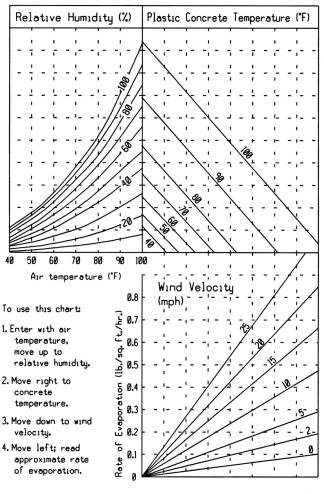
2. Concrete evaporation protection will be based on the theoretical rate of surface
evaporation when it exceeds 0.1 lbs. per square foot per hour. The National Weather
Service’s maximum air temperature, relative humidity and maximum steady wind velocity
without gusts, for the date and the location of the paving pour shall be used for the
Theoretical Rate of Evaporation Chart.
THEORETICAL RATE OF EVAPORATION CHART
3. During hot weather conditions the Jurisdictional Engineer may restrict concrete
placement to early morning or evening hours.
4. Under hot weather conditions the Contractor will advise the Jurisdictional
Engineer of the results of the theoretical evaporation rate throughout paving operations.
The Contractor shall discontinue with placement of the concrete when the theoretical
evaporation rate exceeds to 0.30 lbs./sq.ft./hr.
6. The protection practice by the Contractor will be as follows for the evaporation rate
greater then 0.1 lbs./sq.ft./hr.
a. Immediately apply an approved evaporation retarder (Polymers) to the concrete
pavement and curbs or increase the application cure to 1.5 times the standard specified
rate.
b. Take special precautions to assure that the forms and subgrade are sufficiently
moist or protected to avoid lowering the water content at the pavement/subgrade interface.
In hot weather conditions the subgrade should also be moistened the evening before operations.
c. Assure that the time between placing and curing is minimized and eliminate delays.
d. Moisten concrete aggregates that are dry and absorptive.
e. Use a fog spray to raise the relative humidity of the ambient air if there is a
delay in immediately applying the curing compound.
f. Minimize solar heat by shading, wetting or covering concrete chutes or other
equipment that comes in contact with plastic concrete.
g. If shrinkage cracks should appear during finishing the cracks can be closed by
striking each side of the crack with a float and refinishing.
E. Rain Protection:
1. The Contractor shall have available, near the site of the work, materials for
proper protection of the edges and surface of concrete. Protective material may consist
of sheets of burlap, or plastic film. Planks or other material with suitable stakes that
can be used as temporary forms shall also be on hand;
Iowa DOT 2301.
2. If initial set has not occurred, contractor shall take every precaution necessary
to protect the surface texture of the concrete.
3. Failure to properly protect concrete shall constitute cause for removal and replacement
of defective pavement, if so determined by the Jurisdictional Engineer.
F. Safety Fence for Pavement:
1. The Contractor shall insure that all traffic control devices are in place in accordance
with the Traffic Control Plan.
2. At the end of each day's run and at all side streets, the Contractor shall erect
and maintain such barriers and fencing as are necessary to protect the pavement from damage.
3. Intermediate safety fences may be required for the purpose of opening the slab for
access to a side road, side street, or entrance.
G. Repair of Pavement:
1. The Contractor shall protect the new pavement and its appurtenances from traffic,
both public and that caused by its own employees and agents, at its expense. This includes
the erection and maintenance of warning signs, lights, barricades, watchmen to direct traffic,
and pavement bridges or crossovers.
2. Any part of the pavement damaged by traffic or other causes occurring prior to
final acceptance of the pavement shall be repaired or replaced, at the discretion of
the Jurisdictional Engineer, at the Contractor's expense.
3. The Contractor shall not operate equipment with metal tracks, metal bucket blades,
or metal motor patrol blades directly on new paving. The Contractor shall not unload soil
or granular materials, including base rock for storage and future reloading directly onto
new paving.
H. Utilities Protection:
The Contractor will not start work until all utilities are located.
1. Repairs: When the Contractor disrupts or breaks known utilities of the Jurisdiction
or privately owned utilities, such utilities shall be repaired at the Contractor's expense.
Unnecessary delays in making repairs shall cause the Jurisdictional Engineer to have such
repairs made and the cost thereof deducted from the monies due the Contractor.
2. Drains, Pipe, Tiles: Existing subsurface drains, pipe, and tiles, which are disrupted
or broken by reason of the construction shall be connected to the storm sewer, or another
adequate outlet if storm sewer is not available. Should no outlet be readily available, the
Jurisdictional Engineer shall determine a suitable solution.
3. Water Stop Boxes and Services: The adjustment of stems and castings and/or repair of
those broken or damaged by the Contractor shall be at the contractor's expense. Relocation
of stop boxes and services shall be by bid items.
I. Use of Pavement: Time for opening pavement for use is determined
by age or by test results from cylinder or beams taken during placement.
| MINIMUM AGE OR STRENGTH
OF PAVEMENT BEFORE OPENING |
| Class of Mix |
Type of Cement |
Minimum Age For Opening without Testing(4) |
Minimum Compressive Strength (psi) |
(1)Minimum Flexural Strength Center Point (psi) |
| A |
Type I |
14 Days(2) |
3,000 |
500 |
| B |
Type I |
14 Days |
2,400 |
400 |
| C |
Type I |
7 Days(3) |
3,000 |
500 |
| C |
Type III |
48 Hours |
3,000 |
500 |
| M |
Type I |
48 Hours |
3,000 |
500 |
| C-V47B |
Type I |
7 Days(3) |
3,000 |
500 |
| C-V47B |
Type IP |
7 Days(3) |
3,000 |
500 |
| M-V |
Type I |
48 Hours |
3,000 |
500 |
| M-V |
Type IP |
48 Hours |
3,000 |
500 |
(1) Optional test method for primary roads.
(2) Ten days for concrete 8 inches or more in thickness.
(3) Five days for concrete 9 inches or more in thickness.
(4) Opening without testing only allowed upon approval of Jurisdictional Engineer.
Note: Maturity Method may be allowed with approval of the Jurisdictional Engineer;
I.M. 383 |
J. Restrictions on PCC Overlays and Whitetopping:
1. At temperatures below 55°F, the opening time shall be determined using the maturity method
2. PCC Overlay and Whitetopping concrete shall not be placed when the air temperature is below 40°F.
3. Bonded concrete overlays shall be placed between June 1 and September 30.
4. Unbonded overlays and Whitetopping materials shall not be placed on any HMA when the
pavement surface temperature exceeds 120° F.
All measurements for payments will be made by the Jurisdictional Engineer or authorized
representative.
The quantity of the various items of work involved in construction of concrete pavements
will be measured in accordance with the following provisions.
A. Portland Cement Concrete Pavement: The method of measurement
described herein for portland cement concrete pavement applies to standard or slip form portland
cement concrete pavement, reinforced portland cement concrete pavement and portland cement concrete
base.
1. The area of pavement constructed of the type, class, and thickness specified
shall be computed in square yards from surface measure longitudinally and the nominal
pavement width including integral curb.
2. No deductions shall be made for intakes, manholes or other castings.
3. The area of street returns, paved crossovers, and other similar irregular
areas shall be determined from field measurements using the edges of the main line
pavement as terminals.
4. Pavement Protection: Surface curing and temperature protection covering are
considered incidental to the concrete pavement bid item.
B. Barrier Curb: Barrier curb shall be measured in linear feet.
C. Integral Curb: Construction of integral curb shall be incidental to the construction
of concrete pavement and included in the pavement surface measured for payment.
D. Curb and Gutter: Measurement shall be in linear feet measured along the face of
curb placed unless specified on the plans as incidental with the street paving.
E. Incidental Concrete: Miscellaneous sections of concrete that are required to be
constructed, but not listed as separate bid items, are to be considered incidental to other
concrete bid items and will not be paid for separately. Examples are headers, etc.
F. Concrete Median: Unless otherwise provided, the Jurisdictional Engineer shall
compute in square yards the area of median constructed from measurements of the length along
the surface and the overall width of median. When curb is integral with the pavement the width
shall be measured from back to back of the integral curb.
G. Fixture Adjustment: Refer to Section 2010 for Measurement
and Payment of Fixture Adjustment.
H. Portland Cement Concrete Pavement Samples and Testing: Furnish hardened Portland
Cement Concrete Pavement Samples and testing results required in Section 7010,
3.14. The Contractor will be paid for thickness, smoothness (except 10-foot straight edge)
and strength measurements and testing at the lump sum contract price. This payment shall be full
compensation for furnishing all such samples and test results to the Jurisdiction where required.
All other items listed in Section 7010, 3.14 under the Contractor's responsibility will be considered
incidental to this pay item.
I. Saw Cut: Saw cuts for construction joints in new pavement shall not be measured for
payment.
J. Safety Fence for Pavement: Safety fence for pavement under Section 7010,
1.07, F shall not be measured for payment.
K. Driveway Surfacing Material: The quantity of granular surfacing placed on intersecting
roads, drives, and turnouts shall be computed in tons or in cubic yards as indicated in the contract
documents. The excavation necessary for placement of this material will be incidental to the work
and shall not be measured for payment.
L. Portland Cement Concrete Pavement Widening:
1. The quantity of PCC widening shall be computed in square yards by the Jurisdictional
Engineer from the surface width of widening specified in the contract document and measured
length of the edge of the old pavement.
2. Measurement shall include the widening and all other work not paid for under other items.
M. Concrete Thickness Pay Factor:
1. The bid amount for portland cement concrete pavement shall be adjusted by a "Concrete
Thickness Pay Factor" before final payment is made. If there is a deficient pavement
thickness on a private development project that is intended to be accepted into the jurisdiction
street system, the Jurisdiction will receive the penalty payment prior to acceptance of the work.
2. On the basis of the core lengths, street pavements will be classified in the following bands:
BAND LIMITS |
| Band 1 |
Pavement of design or greater thickness
or deficient by not more than 0.15 inch. |
| Band 2 |
Pavement deficient in thickness by
more than 0.15 inch, but not more than 0.25 inch. |
| Band 3 |
Pavement deficient in thickness
by more than 0.25 inch, but not more than 0.50 inch. |
| Band 4 |
Pavement deficient in thickness by
0.51 inch or more. |
N. Thickness Cores:
1. One four-inch core shall be taken initially for each section of approximately
one thousand (1,000) square yards.
2. For any core outside of Band 1, two additional cores shall be taken in that
section of pavement, and the average of the three cores shall be used.
3. Core locations shall be selected at random by the Jurisdictional Engineer.
4. On widening projects, the Jurisdictional Engineer shall be consulted in the
selection of core locations in an effort to obtain representative cores and avoid
the occasional special locations where corrective measures have been taken only in
the finishing of the concrete in an effort to improve the general profile.
5. It shall be assumed that each original core or additional core is representative
of the pavement thickness for a distance extending one-half the distance to the next
core, measured along center line, or in the case of an initial or final core, the
distance will extend to the end of the pavement section.
6. Irregular Section:
a. The drilling of cores in irregular sections, or on projects involving less
than 2,500 square yards of pavement, base, base widening, or pavement widening,
may be waived by the Jurisdictional Engineer, in which case the designed thickness
will be considered as the measured thickness.
b. If the work is cored, the applicable provisions above shall prevail, except
that a determination of pavement thickness shall not be made on any project on the
basis of less than three cores, and in the case of widening, a given core shall
represent only one lane of pavement, and a minimum of three cores shall be taken
for each lane.
7. At the direction of the Jurisdictional Engineer, the Contractor shall cut samples
from the finished pavement or other course by drilling with a core drill of a size that
will provide samples of a 4 inch outside diameter.
8. Core holes shall be restored by tamping low slump concrete into the hole, and
finishing and texturing the surface. Cores shall be identified and delivered to the
field laboratory or Jurisdictional Engineer.
9. On the basis of core lengths, the pavement or various sections of pavement shall
be classified in the following bands. Core lengths shall be measured as outlined in
IM 347.
| PAY FACTOR FOR CONCRETE
THICKNESS |
| BAND |
PAY FACTOR |
| 1 |
1.00 |
| 2 |
.95 |
| 3 |
.85 |
| 4 |
As determined by the Jurisdictional
Engineer |
10. The Jurisdictional Engineer shall study the extent and severity of the
deficiencies of pavement areas for Band 4. Depending on the severity, the
Jurisdictional Engineer shall require one of the following procedures:
a. The deficient areas shall be removed at the Contractor's expense and
replaced with pavement meeting the contract requirements.
b. A mutually acceptable agreement may be negotiated between the contractor
and the Jurisdictional Engineer which provides a combination of an extended
guarantee period and payment penalty and allows the pavement for the area in
question to be left in place.
O. Pavement Smoothness:
1. Local Streets and Minor Collectors: The costs of correcting the smoothness and
associated traffic control shall be incidental to the cost of pavement. No pavement
smoothness incentives will be provided.
2. Non-Primary Arterials and Major Collectors: The cost of correcting the smoothness
and associated traffic control shall be incidental to the cost of pavement. Price reductions
imposed for noncompliance with the specifications will follow schedule B of Iowa
DOT 2316. No pavement smoothness incentives
will be provided unless specified in the contract documents.
3. Primary Roads: The cost of correcting the smoothness and associated traffic
control shall be incidental to the cost of pavement. Price reductions imposed for
noncompliance with the specifications will follow schedule A of Iowa
DOT 2316.07. Pavement smoothness
incentives will be provided unless otherwise specified in the contract documents.
P. Portland Cement Concrete Resurfacing
1. PCC Resurfacing, Furnish Only: For the number of cubic yards of PCC incorporated
in the work, the Contractor shall be paid the contract unit price per cubic yard. This
payment shall be full compensation for furnishing the concrete mixture and all materials
therefor and for delivery to the grade.
2. PCC Resurfacing, Place Only: For the number of square yards of PCC pavement resurfacing
constructed, the Contractor will be paid the contract unit price per square yard. This payment
shall be full compensation for placing, finishing, protecting and curing the pavement, for
sawing and sealing joints for furnishing and installing reinforcement, for preparation of the
pad line and subgrade, and for meeting all other requirements of Section
7010.
3. Scarification for PCC Resurfacing and Whitetopping: For the number of square yards of
pavement scarified in preparation for PCC Resurfacing or Whitetopping, the Contractor shall
be paid the contract unit price per square yard.
4. Surface Preparation for PCC Resurfacing (Bonded PCC Overlay): For the number of square
yards of pavement prepared by sandblasting or shot blasting, followed by surface cleaning,
the Contractor shall be paid the contract unit price per square yard.
5. Stress Relief Course (Unbonded PCC Overlay): Shall be bid, measured, and paid for in
accordance with Section 7020, 1.04.
2.01 TYPE OF PAVEMENT
Concrete pavement shall be one of two types, standard or slip form.
A. Standard Concrete Pavement: Standard concrete pavement may be reinforced, or
nonreinforced, as noted in the contract documents and shall consist of concrete of the class
specified in the contract documents, reinforced as shown in the contract documents, placed
within forms, and consolidated and finished by equipment operating on forms.
B. Slip Form Pavement: Slip form pavement may be reinforced, or nonreinforced, and
shall consist of concrete of the class specified in the contract documents, reinforced as shown
in the contract documents, placed, consolidated, and finished without the use of fixed forms.
2.02 MATERIALS
A. Portland Cement; Iowa DOT 4101 and
I.M. 401
1. Portland cement shall meet the requirements of AASHTO M 85 specifications for
the type of cement required. Cement which contains 5.0 percent or more of lumps retained
on a No. 20 sieve shall be rejected.
a. Cement which contains less than 1.0 percent of lumps may be used without
adjustment in batch weights. For each 1.0 percent or fraction thereof from
1.0 to 5.0 percent of lumps found by test, batch weights of cement used in
either concrete pavement shall be increased by 2.0 percent of the original value.
b. Cement stored at the site of the work or local warehouses for more than 60 days,
or cement stored in producer's silo more than a year shall be retested for lumps before
using.
2. Type I; Normal Portland Cement:
a. Unless otherwise specified, cement shall meet Type I AASHTO M 85, Type I.
b. When the addition of fly ash to Type I cement is allowed in accordance with
Iowa DOT 2301, or AASHTO M 240, Type I (PM) or Type IP, cement may be furnished
and used within the same limitations.
c. The cement content of the concrete shall be that specified for Type I cement.
B. Mineral Additives:
1. Fly Ash Substitute
a. The use of fly ash may be substituted for Portland Cement in a Portland Cement
Concrete mixture if approved by the Jurisdictional Engineer and shall conform to the
requirements of Iowa DOT 4108,
I.M. 529, and I.M.
491.17. Iowa DOT 2301 shall also apply except
that fly ash substitution rates shall follow the table given in
Section 7010, 2.03
E.
b. Fly ash to be substituted for Portland cement in concrete shall comply with AASHTO M 295,
either Class F or Class C, including the Supplementary Optional Chemical Requirements. Sources
with fly ash between 1.5 percent and 2.5 percent available alkalies may be approved. For Class
C fly ash, the pozzolanic activity test with lime will not be required.
c. Approval of the source of fly ash will be required. This is to be based on fly ash
produced when the power plant is using specific materials, equipment, and processes. Any
change in materials, equipment, and processes shall void the source approval, and a new
approval of the source will be required.
d. Inspection and acceptance of fly ash will be in accordance with Iowa
DOT Materials I.M. 491.17.
2. Ground Granulated Blast Furnace Slag Substitute
a. GGBFS may be substituted for Portland cement in Portland cement concrete
mixes if approved by the Jurisdictional Engineer and shall conform to the
requirements of Iowa DOT 2301,
4108,
I.M. 529 and I.M. 491.14.
b. Inspection and acceptance of GGBFS will be in accordance with Iowa DOT
MaterialsI.M. 491.14, appendix A.
C. Fine Aggregate for Concrete, Iowa DOT 4110:
Clean, hard, durable mineral aggregate particles free from detrimental amount of silt, shale, coal,
or organic matters.
1. Natural sand as a result from disintegration of rock through erosional processes.
2. From an approved source of not more than 2.0 percent shale and coal particles retained
on a No. 16 sieve; not more than 2.5 percent silt by weight.
3. Gradation: Iowa DOT 4109, gradation
No. 1.
| Sieve Size |
Percent Passing |
| 3/8 inch |
100 |
| No. 4 |
90 to 100 |
| No. 8 |
70 to 100 |
| No. 30 |
10 to 60 |
| No. 200 |
0 to 1.5 |
| Jurisdictional Engineer may adjust
gradation to allow for use of local aggregates. |
D. Coarse Aggregate for Concrete, Iowa DOT 4115:
Coarse aggregate shall consist of crushed stone particles.
1. Abrasion loss, in accordance with AASHTO T 96 shall not exceed 50.
2. Freeze and thaw loss, in accordance with Iowa DOT Test Method 211, Method A,
shall not exceed 6 percent.
3. Objectionable Materials: The percentage of such materials shall not exceed the
following percentages:
| Objectionable Materials |
Percent |
| Clay lumps |
0.5 |
| Coal and carbonaceous shale |
0.5 |
| Total of all shale, similar objectionable
materials, and coal combined. |
1.0 |
| Sticks (wet weight) and other organic
materials, except coal. |
0.1 |
| Unsound chert particles retained on
3/8" sieve (Nonstructural concrete) |
3.0 |
| Unsound chert particles retained on the
No. 4 sieve (Gradation No. 6) (½" nominal maximum size) |
0.5 |
| NOTE: Chert particles which
break into three or more pieces when subjected to the freezing and thawing test will
be considered unsound. |
Chert in aggregate produced
from limestone sources is defined as unsound when any of the fractions of the crushed
or uncrushed chert do not meet the soundness requirements. |
4. Durability: Soundness - Iowa DOT Test Method 408-A.
a. Class 2 durability for local and minor collectors; some stone deterioration within 20 years.
b. Class 3 durability for major collectors and arterials; little to no stone deterioration within
20 years.
c. Class 2 durability stone shall be used unless stated otherwise in the contract documents or
otherwise specified by the Jurisdictional Engineer.
5. Gradation: Iowa DOT 4109,
Gradation No. 3.
| Sieve Size |
Percent Passing |
| 1 ½ inch |
100 |
| 1 inch |
95 to 100 |
| ½ inch |
25 to 60 |
| No. 4 |
0 to 10 |
| No. 8 |
0 to 5 |
| No. 200 |
0 to 1.5 |
| Jurisdictional Engineer may
adjust gradation to allow for use of local aggregates. |
E. Water Requirements: Iowa
DOT 4102.
1. Free from detrimental amounts of oil, salts, acids, strong alkalis, vegetable
matter, or other materials detrimental to concrete; AASHTO T 26. If practicable, potable
water shall be used.
2. Suspended matter in excess of 2000 ppm shall be filtered or otherwise clarified.
3. Hardness not more than 750 ppm, as calcium carbonate.
4. Methyl orange, alkalinity, not more than 1,000 ppm, as calcium carbonate.
5. Phenolphthalein alkalinity, not more than one-half the methyl orange alkalinity,
as calcium carbonate.
6. Total acidity, not more than 100 ppm as calcium carbonate.
7. Potable water obtained from a municipal supply, suitable for drinking, may be
accepted without testing.
F. Air Entrainment Admixture: Iowa DOT 4103,
I.M. 403, AASHTO M 154. Provisions shall be made to stir,
agitate or circulate air entraining admixtures prior to use so as to insure a uniform and
homogeneous mixture.
G. Admixtures: All liquid admixtures as listed below must meet the following requirements.
Other admixtures may be used subject to the approval of the Jurisdictional Engineer.
1. Retarding and Water Reducing Admixtures: Iowa DOT
4103, I.M. 403, AASHTO M194.
a. The retarding and water reducing admixture used shall be compatible with the air
entraining agent used.
b. The admixtures shall be used in amounts recommended by the manufacturer for
conditions which prevail on the project.
c. When used, they shall be introduced into the mixer after all other ingredients
are in the mixer.
d. Retarding and water reducing admixtures shall be agitated prior to and during
their use.
e. When fly ash is used in the concrete, the liquid admixture dosage shall be applied
to both the cement and fly ash weight combined.
2. Accelerating admixtures (calcium chloride): Iowa DOT
2529.
a. When calcium chloride is required, it shall be furnished at the job site.
b. Calcium chloride solution shall be a commercial 32 percent solution or equivalent,
prepared by the Contractor as follows:
| |
lbs. solid
per gallon
of water |
Solution produced
per gallon
of water |
| Type 1 - Regular Flake (77% material) |
7 |
1.35 |
| Type 2 - Concrete Flake or pellets (94% material) |
5 |
1.18 |
c. The solution shall be added at a maximum rate of 2.75 gallons per cubic yard of concrete.
d. Mixture shall be agitated until the calcium chloride is completely in solution and agitation
shall be continued, as necessary, to maintain uniformity.
H. Reinforcing Steel:
1. Deformed Bars: Billet steel bar, Iowa DOT 4151.
a. All deformed bars shall be epoxy coated, Iowa DOT
4151.
b. Tie bars shall be bent back reasonably straight. Tie bars broken during rebending shall
be replaced by the Contractor at no cost by drilling a hole and setting the bar in epoxy. Tie
bars shall meet the requirements of ASTM A 615 Grade 40 or 60.
c. All damage to epoxy coated bars shall be repaired by an approved patching material.
2. Plain Bars, carbon steel, ASTM A 306 663, Grade
40. Epoxy coated complying with Iowa DOT 4151.
3. Smooth Dowel Bars, carbon steel, ASTM A 615, grade 40 fabricated from plain bars cut
without deformation of ends; Iowa DOT 4151.
a. Epoxy coated complying Iowa DOT 4151.
b. Dowels, with exception of end of run and header joints, shall be furnished in approved
assemblies.
c. Sawed ends of dowels shall be free of burrs and projections. Sawed ends need not be coated.
d. Assemblies dipped in MC-70, RC-70, RC-250, CRS-1, CRS-2, CSS-1H, HFMS-2, HFMS-2H, or HFMS-2S
prior to delivery to work site.
4. Welded Wire Fabric, Iowa DOT 4151, ASTM A 185.
a. Epoxy coated complying Iowa DOT 4151.
b. Used as conventional reinforcement shall be of the size and spacing shown in the contract documents.
I. Expansion Tubes: Iowa DOT 4191; Fabricated
steel or plastic tubes closed on one end; tubes to be with internal diameter 1/16 inch larger than dowel
bar; bar stop capable of withstanding twenty pounds push, minimum. The stop shall be located at least 2 3/4
inches from the open end of the tube. That part of the tube between the stop and the closed end shall be not
less than the width of the expansion joint.
J. Metal Keyways: Iowa DOT 4191; Fabricated 24 gage
sheet steel; provide lengths in multiples of tie bar spacing; punch at the centerline to receive tie bars;
support metal keyway with legs unless installed by paving machine. Keyways formed on the grade during the
paving operation may be of coated or uncoated sheets of 26 gage iron or steel.
K. Supports for Reinforcing Steel: Iowa DOT 2301.
1. Support tie bars as required to place and maintain correct location during construction.
2. Support dowel bars at expansion and contraction joints.
3. Epoxy Coated Reinforcement: Support with epoxy coated or plastic chairs; tie with plastic
coated tie wires.
L. Joint Fillers and Sealers:
1. Contraction Joint Sealers: Material for sealing sawed contraction and center line joints and
other joints, as shown in the contract documents, shall meet the following requirements:
a. Poured Joint Sealer: Iowa DOT 4136. Hot
poured joint sealer shall be composed of petropolymers and be supplied in solid form.
The sealer shall meet requirements of ASTM D 3405 with the following modifications:
1) Penetration of 90 - 150 at 77 degrees F (25 degrees C).
2) Bond at -20 degrees F (-29 degrees C) standard specimen, 3 cycles, 200% extension, Passes.
b. Cold applied joint sealers meeting the above physical requirements may be used with the
approval of the Jurisdictional Engineer.
2. Preformed Expansion Joint Filler and Sealer: Preformed material for filling expansion
joints shall be one of the following types. When the type is not specified, resilient filler
shall be used.
a. Resilient Filler: Iowa DOT 4136, AASHTO M 213.
Resilient filler shall be furnished in strips of dimensions shown in the contract documents.
1) When the self expanding type is specifically required, the material shall meet
requirements of AASHTO M 153, Type III.
2) Sealer used with these fillers shall meet requirements of
Iowa DOT 4136 or shall be two component,
synthetic polymer type meeting requirements of ASTM D 1850.
b. Polyethylene Joint Filler: Iowa DOT
4136, AASHTO T 42.
1)Polyethylene joint filler shall be resistant to petroleum derivatives
and comply with the following requirements:
a) Compression: 45 p.s.i. maximum
Recovery: 90% minimum
Extrusion: 0.25 inches maximum
2) Sealer used with this filler shall be a two component, synthetic polymer
type meeting requirements of ASTM D 1850.
c. Elastomeric Joint Seals: Iowa DOT 4136,
AASHTO M 220.
1) Elastomeric joint seals shall be of the size and shape designated in the
contract documents.
2) Seals with splices shall be acceptable only when splices are made using
factory type methods. A splice shall not occur within one foot of a sharp bend,
when placed in final position, and no piece shall have more than one splice.
d. Preformed Urethane Foam Expansion Joint Filler:
Iowa DOT 4136, I.M. 436.
1) Preformed urethane foam expansion joint filler shall be made with a semi-open
cell, flexible polyurethane foam which is molded to such cross sectional shape that
it can be easily installed in a 3¼ inch to 4¼ inch wide pavement joint with parallel
sides and shall be sufficiently self locking to prevent the material from floating
out of the joint.
2) The joint filler may be produced in any convenient lengths in excess of 4 feet
and shall have the following cross sectional dimensions:
Top Width 4½ inches plus or minus 1/8 inch
Overall depth 7-3/4 inches plus or minus ½ inch
3) A lubricating adhesive, recommended by the manufacturer for the intended use,
shall be provided with the joint filler.
4) The properties of the urethane foam when determined on skin free specimens
shall meet the following requirements:
Density: 6.5 to 10.0 lb. per cu. ft.
Compressive load, 50% deflection: 20.0 psi, max.
Recovery: 95% min.
Water absorption: 35% by volume, max.
Chemical Resistance. The material shall be resistant to petroleum solvents and linseed oil.
M. Liquid Curing Compounds: Iowa DOT 4105,
AASHTO M 148.
1. Compounds shall be of such consistency that they can be readily applied by
spraying to a uniform coating at a material temperature above 40 degrees F.
2. Moisture Retention shall meet this requirement of Iowa DOT Material Laboratory
Test Method 901.
3. Liquid curing compounds shall dry to the touch in not more than 4 hours.
After 12 hours, the compounds shall not track off the concrete when walked upon.
4. White Pigmented Compounds. Iowa DOT
4105.
a. Shall consist of finely ground, white pigment and vehicle, ready mixed for
use without alteration.
b. The pigment shall not settle excessively or cake in the container.
c. After the compound sprayed on a test slab has dried, it shall have an apparent
daylight reflectance not less than 60 percent relative to magnesium oxide.
d. The compound shall be agitated just prior to being removed from the container
and continuously during application.
5. Dark colored compounds shall consist of asphalt emulsion or asphalt cut back
with a volatile solvent and shall contain not less than 50.0 percent asphalt.
N. Burlap Covering: Iowa DOT 4104.
1. Jute and manilla fibers shall weigh not less than 10 ounces per square yard.
2. Shall be new material or reclaimed material which shall not have a deleterious
affect upon fresh concrete.
O. Pavement Seals: Linseed Oil Emulsion.
1. Shall be non-pigmented and homogenized to produce uniform mixture as set forth
in the United States Department of Agriculture Patent Number 3,873,326.
2. Comply with requirements of ASTM C 309 and C 156.
3. Shall be used on pavements subject to receiving large quantities of salt.
Jurisdictional Engineer will determine pavements to receive linseed emulsion.
4. Apply after curing compound has dried.
P. Epoxy Bonding Compound: Iowa
DOT 2301 and I.M. 491.17491.11.
1. Epoxy bonding compound (polymer grouts) shall meet the requirements of
Iowa DOT 2301 and
I.M. 491.17491.11
for each particular application.
2. The material shall be an approved brand as listed in I.M.
491.17491.11.
Q. Concrete Overlays and Whitetopping: Material requirements for concrete overlays and
whitetopping shall be as described for standard PCC paving except as modified below:
1. Bonded Overlays
a. Aggregate:
1) Coarse aggregate type (crushed limestone or gravel) shall be same
as the existing pavement as indicated in the contract documents.
2) Coarse aggregate shall meet Iowa DOT 4115,
Gradation No. 5
3) The largest particle size of the coarse aggregate shall be less than or equal to
one-third of the overlay thickness.
b. Concrete Mix: C-3WR mixture, with or without flyash.
c. For projects with mainline paving greater than 50,000 square yards, a QM-C design
mixture as described in Iowa DOT 2310 shall be
used.
2. Unbonded Overlays: HMA Stress Relief Course
a. Asphalt Binder: PG 58-28
b. Mixture: 300,000 ESAL, 3/8 inch mix, per Iowa
DOT 2303.
1) No maximum film thickness restriction
2) No minimum filler/bitumen ratio restriction
c. Aggregate:
1) Type B
2) No percent crushed particle requirement
3) Gradation shall fall below the restricted zone.
2.03 MIXES: IOWA DOT IM 529
A. Mix Design: Unless otherwise specified, the mix design shall be Class C or C-V47B
mix with air entraining. If a different mix is specified in the contract documents or if the
Contractor requests a mix different than C or C-V47B, the Contractor shall submit to the
Jurisdictional Engineer the paving mix design for approval two weeks prior to starting paving
operations. The submittal shall contain the mix number as described below and admixtures in
accordance with Section 7010, 2.03E. Unless otherwise specified, the minimum
compressive strength of the mix shall be 4,000 pounds per square inch at 28 days.
B. Mix Number: Mix numbers designate numerous aspects of the particular mix. The
following is an explanation of the various aspects of the mix number. For example: C-4WR-C10.
1. The first letter designates the class of concrete as designated in the contract
documents.
2. The number indicates the relationship of coarse aggregate to fine aggregate. A mix
with a 4 is a 50/50 mix. The following chart shows the number within the mix number and
the proportions of the aggregates for each number:
2 is composed of 40% fine and 60% coarse.
3 is composed of 45% fine and 55% coarse.
4 is composed of 50% fine and 50% coarse.
5 is composed of 55% fine and 45% coarse.
6 is composed of 60% fine and 40% coarse.
7 is composed of 65% fine and 35% coarse.
8 is composed of 70% fine and 30% coarse.
3. The letters WR indicate water reducer is used in this mixture.
4. When a C or an F is shown toward the end of the mix number, fly ash is a part of
the mixture and C-fly ash or F-fly ash, respectively, is used. The percentage of fly ash
being used in the mixture shall be designated at the end of the mix number.
5. In certain mix designations, the letter V appears after the first hyphen. This
indicates that a Class V aggregate is to be used. If no letter is shown, aggregate
other than Class V shall be used.
C. Concrete Mixes: Shall meet the following design targets, as per
Iowa DOT 2301,
IM 529.
| |
|
|
Basic Absolute
Volumes of Materials for Unit Volume of Concrete |
| Mix |
W/C Basic |
W/C Max. |
Cement Min. |
Water |
Entrained Air |
Fine Aggregate |
Course Aggregate |
| A-4(1) |
0.474 |
0.532 |
0.108 |
0.161 |
0.060 |
0.335 |
0.336 |
| B-4(2) |
0.536 |
0.600 |
0.093 |
0.157 |
0.060 |
0.345 |
0.345 |
| C-3WR |
0.430 |
0.489 |
0.108 |
0.146 |
0.060 |
0.309 |
0.377 |
| C-4 |
0.430 |
0.488 |
0.118 |
0.159 |
0.060 |
0.331 |
0.332 |
| C-4WR |
0.430 |
0.489 |
0.112 |
0.151 |
0.060 |
0.339 |
0.338 |
| M-4 |
0.328 |
---- |
0.156 |
0.161 |
0.060 |
0.312 |
0.311 |
| O-4WR |
0.327 |
----- |
0.156 |
0.160 |
0.060 |
0.312 |
0.312 |
| (1) Concrete Base, temporary
pavement, or recreation trails only. |
| (2) Temporary or recreation
trails only. |
| Other approved mixes will follow
Iowa DOT IM 529. |
| |
Basic Absolute Volumes of
Materials for Unit Volume of Concrete |
| |
W/C Basic |
W/C Max. |
Cement Min. |
Water |
Entrained Air |
Class V. |
Limestone |
| C-V47B |
0.440 |
0.560 |
0.107 |
0.148 |
0.060 |
0.479 |
0.206 |
| M-V |
0.390 |
---- |
0.160 |
0.196 |
0.060 |
0.555 |
0.029 |
The above mixtures are based on Type I cements (Sp. G. = 3.14). Mixes using blended
cements (Type IP, I(PM), IS, or I(SM)) must be adjusted for specific gravities listed
in Iowa DOT IM 401.
D. Consistency and Workability: The amount of materials
used shall produce a concrete of uniform consistency, workability and a satisfactory
surface finish.
| Paving |
Type of Concrete |
Slump-in |
% Air Content of Fresh
Unconsolidated Concrete
(Before Paver) |
Target % Air,
Consolidated
Concrete
(After Paver) |
| Min. |
Max. |
Target
or
Initial* |
Acceptable
Range |
| Minus |
Plus |
| Machine Finish |
A, B, C, C-V47B |
½ |
2½ |
7.5 |
1 |
1 ½ |
6 |
| Hand Finish |
A, B, C, C-V47B |
½ |
4 |
7 |
1 |
1 ½ |
6 |
| Curb & Gutter |
C, C-V47B |
---- |
3 |
7 |
1 |
1 |
6 |
| Base (Machine Finish) |
A |
½ |
2½ |
7 |
1 |
1 ½ |
6 |
| Base (Hand Finish) |
A |
½ |
4 |
7 |
1 |
1 ½ |
6 |
| Patches with CaCl |
M, M-V |
1 |
3 |
5** |
2 |
2 |
N/A |
| Patch w/o CaCl |
M, M-V |
1 |
3 |
6 ½ |
1 ½ |
1 ½ |
N/A |
As per Iowa DOT 2301, 2511,
2512, 2529, and
2530.
* The initial values for fresh concrete listed in the table above account for anticipated air
loss during consolidation of concrete during placement and paving. Actual air loss and target value
for air content of fresh concrete are established below.
** Prior to addition of Calcium Chloride
E. Air Content for Mainline Paving:
1. Establishing the Target Air Content
a. On the first day of paving, the air content of fresh, unconsolidated concrete shall
be in accordance with the table above for Initial Air Content.
b. The air content of concrete before and after consolidation (in front of and behind
the paver), shall be tested within the first 10 loads. The air content behind the paver
shall be checked at two locations. Samples behind the paver shall be taken such that they
are representative of the entire cross section (one sample from each side of the slab) and
the results averaged.
c. The target air content for fresh, unconsolidated concrete for a specific concrete
mixture and paver shall be established based on the initial samples taken. The air loss
due to consolidation (the difference in air content before and after the paver) shall be
added to the target value for finished concrete and rounded to the next higher 0.5% to
establish the target air content for fresh, unconsolidated concrete.
2. Minimum Testing Frequency
a. The air content of fresh, unconsolidated concrete (in front of the paver) shall be
tested every 200 CY.
b. The target air content for fresh, unconsolidated concrete shall be reestablished
whenever the concrete material sources, concrete mix, and/or paver are changed
3. Adjustments
a. The air content of the fresh, unconsolidated concrete shall be maintained at the
established target air content within the range allowed by Section 7010,
2.03D.
b. A new target air content for fresh concrete shall be established, and the mix adjusted
as required, if the loss through the paver changes by more than 0.5% from the previously
established air loss.
F. Use of Fly Ash: The Contractor shall notify the Engineer prior to making concrete mixture
changes which have been approved. Mix proportions for the various mixes using fly ash are included in
the Iowa DOT Materials IM 529.
The following fly ash substitution rates shall replace those given in
Iowa DOT 2301 and as referenced in Iowa DOT IM 529:
Fly Ash Substitution Rates
| Time Period |
Cement Type |
Fly Ash Substitution Rate
by Weight |
March 16 through
September 14 ***
March 16 through
September 14 *** |
Type I and Type II
Type IP and
Type I(PM) |
Not more than 20 percent
Not more than 5 percent * |
September 15 through
October 15
September 15 through
October 15 |
Type I and Type II
Type IP and
Type I(PM) |
Not more than 15 percent
None |
October 16 thru March 15
October 16 thru March 15 |
Type I, Type II, & Type III
Type IP and Type I(PM) ** |
None
None |
| March 16 thru October 15 |
Type I, Type II, or Type III
used in Class M mixtures |
Class C fly ash only at not
more than 10 percent |
| * Note: If the cement manufacturer
provides the Jurisdictional Engineer with satisfactory concrete strength and freeze-thaw
durability test results equivalent to concrete with the same Type IP or Type I(PM) cement
without fly ash, the substitution rate may be increased to 10 percent. The testing and
acceptance criteria shall be in accordance with Materials
IM 401. |
| ** Note: Proportions of Type IP and
Type I(PM) shall be increased 15 percent, by weight, during this time period. |
| *** Note: The March 16 through
September 14 substitution rate may be used at any time the maturity method for monitoring
concrete strength is utilized. |
Fly ash shall be transported, stored, hauled, and batched in such a manner to keep it dry.
2.04 MIXING EQUIPMENT
A. Weighing and Proportioning Equipment: Iowa DOT
2001.
B. Mixing Equipment: Iowa DOT 2001.
C. Material Bins: Iowa DOT 2001.
2.05 CONCRETE BATCHING: IOWA DOT 2301
A. Plant batching shall be Iowa DOT calibrated and approved. Provide copy of current calibrations
and approvals.
B. Batch plant operation and batch trucks shall be coordinated with the paving operation in order
to ensure a steady supply of materials.
C. Batch plant and trucks shall be operated to minimize dust, noise or truck nuisances.
2.06 CONCRETE MIXING
A. Construction or Stationary Mixer: Iowa DOT
2301.
1. The concrete shall be uniform in composition and consistency. If this condition is not
produced because of the size of the batch, the size of the batch may be reduced or the mixing
time increased, or both, until this result is obtained. If non-uniform, concrete producers
shall take corrective action.
2. Concrete transported without continuous agitation shall not be used if the period elapsed
between the time the concrete is mixed and the time it is placed is greater than 30 minutes. The
mixed-to-placed time period may be extended an additional 30 minutes with the use of a retarding
admixture, upon approval of Jurisdictional Engineer.
3. Concrete transported with agitation shall not be used when the time between start of mixing
and placement is more than 90 minutes.
4. The methods of delivering and handling the concrete shall be such that objectionable
segregation or damage to the concrete will not occur, and that which will facilitate placing
with a minimum of handling.
5. The compartment in which concrete is transported to the work shall be thoroughly cleaned
and flushed with water at such intervals as may be necessary to insure that hardened concrete
will not accumulate in the compartment. Flushing water shall be discharged from the compartment
before it is charged with the next batch.
B. Ready Mixed Concrete: Iowa DOT 2301.
1. The concrete shall be uniform in composition and consistency. If non-uniform, concrete
producers shall take corrective action.
2. Proportioned in a central plant and mixed in a stationary mixer for transportation in
trucks without agitation.
3. Proportioned at a central plant, and only partially mixed in a stationary mixer for
transportation and finish mixing in a transit mixer.
4. Proportioned at a central plant, and then mixed in a transit mixer prior to or during
transit.
5. When necessary to add additional mixing water at the site of placement, the batch shall
be mixed at least an additional 30 revolutions of the drum at mixing speed.
6. For main portions of the work it must be demonstrated before the work starts that each
vehicle in which concrete will be delivered is capable of discharging concrete having a slump
not over 2 inches at an overall rate for its entire load of not less than 1.25 cubic yards per
minute. The concrete shall be delivered at a rate sufficient to maintain a sustained rate of
progress of not less than 100 feet per hour for the width and depth of slab to be placed.
7. Concrete transported without continuous agitation shall not be used if the period elapsed
between the time the concrete is mixed and the time it is placed is greater than 30 minutes.
The mixed-to-placed time period may be extended an additional 30 minutes with the use of a
retarding admixture upon approval of the Jurisdictional Engineer.
8. Concrete transported with agitation shall not be used when the time between start of
mixing and placement is more than 90 minutes. However with the approval of the Jurisdictional
Engineer, an approved retarding admixture may be used at the rate prescribed in Materials
IM 403.
9. The compartment in which concrete is transported to the work shall be thoroughly
cleaned and flushed with water at such intervals as may be necessary to insure that hardened
concrete will not accumulate in thecompartment. Flushing water shall be discharged from
the compartment before it is charged with the next batch:
a. Concrete with Type III cement and transported without agitation shall be delivered
and placed within 30 minutes after mixing.
b. With the approval of the Jurisdictional Engineer, an approved retarding admixture
may be used at the rate prescribed in Materials IM
403 and the mixed-to-placed time may be extended by an additional 30 minutes.
C. All Methods: Each truck load shall be identified by a plant charge ticket showing
plant name, contractor, project data, quantity, class, time batched, and water added at site.
2.07 CONCRETE PLACEMENT EQUIPMENT: IOWA
DOT 2301
A. Subgrade Finishing Equipment: Use mechanical excavating equipment designed for this
purpose, approved by Jurisdictional Engineer.
1. Form line or path area for slip-form paving machine shall be constructed to final
grade by form-line excavating equipment with automatic grade controls.
2. Subgrade between forms or between path areas for slip-form machines constructed to
final grade with automatically controlled subgrade excavating machine.
B. Side Forms: Steel, minimum thickness: 5 gage, height at least equal to design
thickness of pavement with base width at least 6 inches.
1. Minimum section length: 10 feet, joint connections designed to permit horizontal
and vertical adjustment with locking device to hold abutting sections firmly in alignment.
2. Bracing, support, and staking must prevent deflection or movement of forms.
C. Flexible Forms: Use steel or wood flexible forms for curves with radius less than
100 feet.
1. Bracing, support, and staking must prevent deflection or movement of forms.
2. Forms used to form back of curbs at returns shall have height at least equal to design
thickness of pavement and curb height.
3. Forms must be free from scale and surface irregularities; coat with release agent (see
Section 7010, 3.03.G) prior to concrete placement.
D. Consolidating and Finishing Equipment: Fixed form or slip form paving machines
specifically designed for placing, striking off, consolidating, and finishing in single pass to
required cross section.
1. Consolidation of concrete by single pass of approved surface, tube, or internal vibrator
operated in accordance with manufacturer's recommendations.
2. Slip form equipment: Automatic horizontal and vertical controls required; equipment
must spread concrete to uniform depth prior to finishing.
3. Air screeds and vibrating screeds are approved consolidating and finishing equipment
for cul-de-sacs, drives and some intersections. Small runs of pavement up to 250 feet maximum
may also require screeds if paving machines are not practical.
4. Equipment subject to approval of Jurisdictional Engineer.
E. Hand Finishing Equipment: Contractor shall provide tools including wood or magnesium
floats, wood hand floats, point trowels, edgers, or other equipment necessary for proper finishing
of concrete.
1. Provide 2 light straightedges, 10 feet long, with handles not less than 12 feet long for
use in detecting irregularities in surface; provide 2 heavy straightedges of similar size for
use in correcting surface; provide 2 light straightedges 10 feet long for checking curb and
gutter line.
2. Provide approved vibrators for consolidating concrete.
3. Provide metal or wood screed true to crown.
F. Curing Equipment: Use pressure sprayer capable of applying a continuous uniform film
of curing compound.
G. Concrete Saws: Power operated concrete saws capable of cutting hardened concrete neatly.
H. Joint Sealing Equipment: Equipment capable of heating and installing sealant in joints
in accordance with manufacturer's recommendations.
2.08 Surface Preparation and Cleaning Equipment:
A. Cold Milling machine capable of scarifying existing surface to the depth required
B. Shot blasting machine capable of removing rust, oil, and concrete laitance from existing
surface.
C. Sand blasting equipment capable of removing rust, oil, and concrete laitance from the
existing surface.
3.01 FINAL SUBGRADE/SUBBASE PREPARATION
A. Natural Subgrade:
1. Subgrade construction shall meet the requirements of Section
2010, Part 3.
2. Should the subgrade be left high or not prepared for final template shape by a previous
contractor, the subgrade shall be proof rolled and depressions filled in accordance with
Section 2010.
3. Trimming:
a. If the subgrade is to be trimmed to the final grade elevation with an
automatically controlled trimming machine, the prepared subgrade shall be graded
to an elevation that will permit the machine to accomplish the final cut in one
continuous forward pass.
b. In irregular or short sections, the subgrade shall be checked by the most
accurate practical method, subject to approval of the Jurisdictional Engineer.
4. Unless otherwise ordered by the Jurisdictional Engineer, the subgrade, at time of
placing concrete for Concrete Pavement, shall be in a uniformly moist but not muddy condition
to a depth of not less than one inch.
5. Subgrade Loading:
a. Where concrete trucks must travel on a prepared soil-type subgrade to unload
and, as approved by the Jurisdictional Engineer, watering of the subgrade must be
limited to just ahead of the paving machine.
b. Repetitive loading on the subgrade by concrete trucks shall be minimized by
entering and exiting the subgrade on side streets.
c. Loads in excess of the legal axle load shall not be allowed on the completed
subgrade.
d. Partially loaded trucks may be required.
e. If subgrade/subbase failure occurs, the repair shall be coordinated with the
Jurisdictional Engineer.
6. Paving Suspended:
a. The paving operation shall be suspended where subgrade stability has been lost.
b. No concrete shall be placed upon a subgrade which has become unstable, bears
ruts or tire marks of Contractor's equipment or which is excessively softened by
rain until such subgrade has been reconsolidated and replaned or reshaped to correct
the objectionable condition.
c. If necessary, scarify to a minimum depth of 6 inches, aerating, and recompacting
at the Contractor's expense. Recompaction shall meet requirements of
Section 2010, 3.07.
7. Maintenance of Subgrade:
a. The Contractor is responsible for maintenance of the completed subgrade during
subsequent construction activities.
b. Before allowing hauling equipment to use the completed subgrade, the Contractor
must be satisfied as to the effect this hauling equipment may have on the partially
completed work.
B. Granular Subbase:
1. Granular Class A, B, C, and D subbase construction shall meet the requirements of
Section 2010, 2.04 D and Section
2010, 3.09.
2. Should the Contractor who constructed the subbase elect to overbuild the subbase,
the paving contractor shall trim down to the design elevation and shape to the final
template with an automatically controlled trimming machine.
3. Excess material shall be salvaged and spread for use on any other approved project
location or operation.
4. The top 1 inch of the subbase shall be uniformly moist prior to paving.
5. Construction traffic may be allowed only on Class A subbase (special backfill),
Class C subbase (RAP special backfill), and Class D subbase (modified) upon approval
of Jurisdictional Engineer. (See Section 2010, 3.09, E, 4)
6. The paving operation shall be suspended where subbase stability has been lost.
3.02 SURFACE FIXTURE ADJUSTMENT
A. Adjust manhole frames and other fixtures within area to be paved to conform to
finished surface.
B. Clean outside of fixture to depth of pavement before concrete placement.
C. Box out fixtures for later adjustment where allowed. Size and shape of box out
for intakes as shown in Standard Drawings.
3.03 FORMS SETTING
A. Use form line excavating machine to establish subgrade of forms.
B. Set base of forms at or below subgrade elevation with top of forms at pavement
surface elevation.
C. Extra height forms with Jurisdictional Engineer approval may be used to back
up integral curb and paving slab; set base at or below subgrade elevation with top
of form at top of curb elevation.
D. Secure forms in place to required grade and alignment.
E. If voids occur under forms, remove forms and rework subgrade to proper elevation
and density; reinstall forms.
F. If the soil supporting the form is softened by rain or standing water so that
form is inadequately supported, remove forms and rework subgrade to proper elevation and
density; reinstall forms.
G. Coat forms with release agent before concrete is placed.
H. Place forms true to alignment and free of latent concrete.
3.04 REINFORCING PLACEMENT
A. Reinforcing metal shall be clean, straight, free from distortion and rust, and shall
be firmly secured in position as detailed.
B. All reinforcing metal shall be placed in approved storage to prevent damage; do not
distribute along the work site except as needed to avoid delay in paving.
C. Place reinforcing steel as shown on the detailed drawings or as specified; support
and secure bars by approved chair and wire assemblies; bars to be checked by the
Jurisdictional Engineer upon notification from the Contractor.
D. Place steel centered in the pavement reasonably in advance of the paving operations.
E. Joint Steel:
1. All joints shall be constructed of the type, dimensions, and at the locations
required by the plans or special provisions.
2. Tie bars for all longitudinal joints shall be installed so as to be in the
intended position in the completed pavement. Tie bars for all longitudinal joints
shall be positioned on chairs and secured against movement with metal stakes during
placing and finishing of concrete unless otherwise approved by the Jurisdictional
Engineer. If approved by the Jurisdictional Engineer, bars may be placed in position
by a machine or other method. For tie steel that is placed mechanically in plastic
concrete, the Jurisdictional Engineer shall:
a. Manually check locations and depth of the steel in the plastic concrete
behind the slip form paver using the following frequencies:
- once every 200 lineal feet for tangent roadway sections
- in at least three locations within all horizontal curve sections
- for each inspection, at least two tie steel locations within a panel
b. Using a magnetic locator, verify locations of tie steel in hardened concrete
every day. Check out-of-tolerance tie steel to identify the extent of the problem
for a retrofit correction.
3. The Contractor shall provide adequate means to ensure that the load transfer
devices and tie bars for key type joints are properly secured to maintain correct
position and alignment during the placement of concrete.
4. Other tie bars shall be placed in such a manner as to ensure that the bars are
located in reasonably close conformity with the specifications.
5. Care should be taken to prevent disturbance or damage of the joint assembly.
Bars must be supported by approved chairs or method approved by Jurisdictional Engineer.
F. Dowel Holes:
1. Holes for both deformed and smooth dowel bars shall be drilled into the face of
the existing slab at midpoint.
2. Drills used to make holes shall be held in a rigid frame to assure proper
horizontal alignment with misalignment not to exceed 1/4 inch in the vertical or
horizontal plane.
3. The equipment used shall be operated so as to prevent damage to the pavement
being drilled. The drilling procedure shall be approved by the Jurisdictional Engineer.
The hole shall be blown clean to eliminate all dust.
4. Dowels shall be epoxied into place in the existing slab. Epoxy bonding compound
shall meet requirements of Section 7010, 2.02 P.
G. Bar Mats:
1. When bar mat assemblies are specified, the reinforcement shall be assembled
accordingly and firmly fastened together at all bar intersections.
2. Mat assemblies shall be placed, secured, latched and tied for a continuous mat
at adjacent ends as detailed on the plans. Displacement during concrete placement
operations shall not be permitted.
3. Mat assemblies shall not be placed without the use of chairs to assure proper
positioning; maintain to proper clearances.
H. Steel Fabric: When fabric is specified, it shall be placed in sheets at the
depth shown on the plans.
3.05 CONSTRUCTION OF JOINTS (See
Figures 7010.1 A through 7010.4 C)
A. General:
1. Longitudinal and transverse joints shall be constructed of the type, dimensions,
and at the locations required, as described by these specifications, or as detailed
by the plans or special provisions.
2. Longitudinal joints shall be coincident with or parallel to the pavement center
line unless shown otherwise on the plans.
3. All transverse joints shall be at right angles to the center line and shall
extend the full width of the pavement unless otherwise specified.
4. All joints shall be perpendicular to the finished grade of the pavement and
the alignment across the joint shall not vary from a straight line by more than 1
inch.
5. All joint fillers shall be installed as shown in the contract documents.
6. The Contractor shall exercise care in placing, consolidating, and finishing
the concrete at and about all joints.
7. The edges of the pavement at tooled joints shall be rounded, where required,
as specified on the standard detailed plates.
8. Wet sawing shall be used when required by the contract documents for dust control.
B. Expansion Joint:
1. Install expansion joints where shown on plans and as shown on Standard Drawings.
2. Prevent movement of or damage to joint assembly when placing concrete; set joint
material low enough to clear the finish machine.
3. Construct double width expansion joint in curb over expansion joint in pavement.
The backside of the joint must be clear of concrete.
4. The expansion joint shall be aligned straight and true.
5. If joint fillers are assembled in sections, or if joints as a whole are constructed
in sections, then no offsets shall be between adjacent units.
6. Where more than one section is used in a joint, the sections shall be securely
laced or clipped together. Damaged basket assemblies shall not be used.
C. Saw Joints:
1. Joint locations shall be chalked with a string line before sawing.
2. Joint dimensions:
a. All transverse contraction joints shall be sawed at a maximum spacing of 21T,
where T is the thickness of the pavement in feet.
b. All joints shall be sawed to a depth shown below and on the detail plate.
| |
Minimum Sawcut Depth |
| |
Conventional Saw |
Early "Green" Saw |
| Transverse "C" Joint |
T/3 |
1 ¼" |
| All other Transverse Contraction joints |
T/3 |
1 ¼" |
| Longitudinal Joint |
T/3 |
Not Allowed |
c. The Contractor shall closely monitor joint sawing for both longitudinal and
transverse joints for depth and spacing and immediately report any deviations from
the specifications. The Contractor shall take immediate steps to correct any
deviations.
3. In order to prevent shrinkage cracks, sawing shall be commenced promptly after
the pavement has obtained sufficient strength to resist tearing of the concrete adjacent
to the joint during the process of sawing.
4. Pavement pours shall be scheduled to allow transverse joints to be sawn within 24
hours of the concrete being placed.
5. Longitudinal joints shall be sawn within 24 hours of the concrete being placed.
6. If necessary, the sawing operations shall be carried on both day and night.
7. Joints sawed with an early "green" concrete saw shall be washed out
prior to sealing. The concrete must be capable of supporting the sawing operations to
allow the use of an early green concrete saw.
D. Construction Joints:
1. Longitudinal or transverse construction joints shall be placed between adjacent
lanes of concrete and at end-of-day header runs.
2. Manhole boxouts shall be located and placed on grade prior to paving. Manhole
boxouts are required for two piece castings for sanitary/storm manholes. (See
Figure 7010.2).
3. The longitudinal construction joints shall be an approved key type joint with
legs unless machine placed.
4. Transverse construction joints shall employ load transfer devices (Header) and
shall be placed whenever concrete placement is delayed for more than 30 minutes.
5. Saw and seal to the dimensions shown for a "B" joint on the detail plate
(Figure 7010.4A and 7010.4B).
E. Joints for PCC Resurfacing: Refer to Section 7010, 3.13
3.06 CONCRETE PAVEMENT PLACEMENT
A. Set survey control stakes at 25 foot maximum spacing including high and low points.
Additional staking may be required by the Jurisdictional Engineer.
B. The concrete shall be placed, consolidated, and finished to the widths and depths
outlined in the plans.
C. Integral curbs shall be poured with the slab in a single paving machine operation.
Normal mainline paving will not have construction joints at integral curbs.
D. The concrete shall be deposited upon the supported reinforcement keeping segregation
to a minimum.
E. Concrete shall be deposited to the full depth of the pavement in a single operation.
F. Necessary hand spading and spreading shall be done with shovels and not rakes.
G. Use paving machine for all uniform width slabs 8 ½ feet or more in width and 250 feet
or more in length.
H. When pavement is constructed in separate lanes, the junction line in straight sections
shall not deviate from the true line shown on the plans by more than ½ inch at any point and
shall be tooled to the radius shown on the plans. A joint formed with a metal keyway shall
be used between separately poured lanes.
I. Place concrete to full depth in single operation. Keep a uniform pile of concrete
in front of the paving machine, up to a maximum of 6 to 8 inches above the design surface
elevation.
J. The concrete shall be distributed and spread as soon as placed. A mechanical concrete
spreader may be used.
K. Concrete Screed:
1. The concrete shall then be struck off and screeded by mechanical means.
2. The striking off or screeding shall conform to the crown and cross section
shown on the plans.
3. If, in the operation of subgrade or finishing equipment, it is necessary to
operate one or both sets of wheels or tracks on previously placed concrete, the
wheels or tracks shall be adjusted so that the bearing on the concrete will be not
less than 3 inches from the edge of the pavement.
4. When operating with two wheels on the previously placed concrete and two wheels
on the form, the form wheels shall be double flanged.
5. All wheels operating on the pavement shall be flangeless and rubber tired.
All tracks operating on the pavement shall use rubber, wood, or belting pads.
L. The top of the forms shall be kept clean from accumulations of concrete, and the
travel of the finishing machine on the forms shall be maintained true without lift,
wobbling, or other variations tending to affect precision of finish.
M. When finishing by hand methods, concrete shall be consolidated by use of vibrating
units operating in the concrete. Unless the vibrating apparatus is such that the full width
of concrete is consolidated in a single passage, a definite system or pattern shall be used
in the operation of the vibrator so the full width of concrete in each linear foot of lane
will receive adequate and uniform consolidation. The system and methods of vibrating shall
be subject to approval the Jurisdictional Engineer. Vibrating equipment shall meet the
requirements of IDOT Section 2301.07.
Vibrating equipment shall, under no circumstances, be used as a tool for moving concrete
laterally on the grade.
3.07 CURB AND GUTTER CONSTRUCTION (See Figure
7010.7A)
A. Construct curb and gutter as shown on Standard Drawings.
B. Use paving machine slip-form for curb; curb mule or similar mechanical equipment
providing equivalent results.
C. Hand methods shall be allowed for radius, returns, and sections of curb and gutter
100 feet or less in length.
D. When depressed curb at driveways and where sidewalk intersects street, use templates
to form backs of such curbs. See standard plates for shape of depressed curbs.
E. Form and construct curb by hand only where barrier or depressed curb is required and
where small radii or other special sections preclude use of mechanical equipment.
F. Finish curb as rapidly as finishing operations on pavement permit. Maximum distance
behind paving machine is 100 feet.
G. Remove free water, latency, dust, leaves, or other foreign matter prior to placing
concrete for curb.
H. Use freshly mixed concrete; do not store concrete in receptacles at side of pavement
for use in curb at a later time; do not use concrete requiring retempering.
I. Vibrate or puddle concrete to secure bond with paving slab and eliminate rock pockets.
J. Secure final finish on curbs by hand method, including 6 foot straightedge or 6 foot slipform.
K. Edge, protect, and cure curb in same manner as pavement.
L. Check surfaces of curb and gutter with 10 foot straightedge; correct variations greater
than 1/8 inch; remove and replace curbs having varying cross section.
3.08 FINISHING
A. Grade and Crown: Promptly after concrete has been placed and vibrated, the
surface shall be struck off to the true section by the screed. The surface shall be
finished true to crown and grade.
B. Watering the Surface: The practice of lubricating the pavement surface
with wet burlap or by sprinkling water from brushes or from sprinkler containers to
afford greater ease in finishing operation shall not be allowed.
C. Floats: Finish surface with wood or magnesium floats; finish from both
sides simultaneously if pavement is placed to full width with one pass of paving machine.
D. Straight Edging:
1. After the longitudinal floating has been completed and the excess water has
been removed, and while the concrete is still plastic, the slab shall be tested for
trueness with a channel radius float, or approval equal. ("channel radius float"
is manufactured by Owens Industries, Inc.)
2. The channel radius float shall be held in successive positions parallel to the
road center line in contact with the surface and the whole area worked from one side
of the slab to the other as necessary.
3. Advancement along the pavement shall be in successive stages of not more than
one half the length of the channel radius float.
4. Any depressions found shall be immediately filled with freshly mixed concrete,
struck off, consolidated, and refinished.
5. Check surface longitudinally while concrete is still plastic; correct any
surface deviations greater than 1/8 inch in 10 feet. Round edges of pavement to
1/8 inch radius.
E. Surface Treatment:
1. Dragged Surface Treatment: Unless otherwise specified, the finished surface
shall be textured with a dragged surface treatment
a. Astroturf or burlap shall be dragged longitudinally over the finished surface
to produce a tight, uniform, textured surface, and the edges shall be rounded in a
workmanlike manner.
b. The Astroturf or burlap drag shall be removed from the pavement surface
at regular intervals and cleaned with water to remove accumulated concrete from the
fabric in order to maintain a consistent finished texture.
c. When, for any reason, the desired texture normally obtained by the drag is not
secured, the Jurisdictional Engineer may require that the final finish be a broom
finish, in lieu of or in addition to the drag.
2. Surface Tining: When surface tining is specified it shall consist of a longitudinal
tined treatment unless specifically modified in the contract documents.
a. Longitudinal surface tining shall be done with a mechanical device such as a
wire broom or comb. The broom or comb shall have a single row of tines 1/8 inch
(+/- 1/64 inch) in width. The tines shall be uniformly spaced at 3/4 inch intervals.
The depth of the grooves shall be a minimum of 1/8 inch to a maximum of approximately
3/16 inch in the plastic concrete.
b. This operation shall be done at such time and in such manner that the desired
surface texture will be achieved while minimizing displacement of the larger aggregate
particles and before the surface permanently sets.
c. Along the length of longitudinal joints a 2 to 3 inch wide strip of pavement
surface, centered over the longitudinal joint, shall be protected from longitudinal
tining.
d. Longitudinal tining shall be accomplished by equipment with horizontal and
vertical string line controls to ensure straight grooves.
3. Under special circumstances, when specifically called for in the contract documents,
transverse tining may be required.
a. If transverse surface tining is required, it shall be done with a mechanical
device such as a wire broom or comb. The broom or comb shall have a single row of
tines, 1/8 inch (+/- 1/64 inch) in width. The tines shall be randomly spaced from
3/8 inch to 1 5/8 inch with no more than 50 percent of the spacing exceeding 1 inch.
The depth of the groove shall be a minimum of 1/8 inch to a maximum of approximately
3/16 inch in the plastic concrete.
b. This operation shall be done at such time and in such manner that the desired
surface texture will be achieved while minimizing displacement of the larger aggregate
particles and before the surface permanently sets.
c. Where abutting pavement is to be placed, the tining should extend as close to
the edge as possible without damaging the edge.
d. If abutting pavement is not to be placed, the 6 inch area nearest the edge or
1 foot from the face of the curb shall not be tined.
e. For small or irregular areas, or during equipment breakdown, tining may be done
by hand methods.
F. Edge Finish: Before the concrete has taken its initial set, all edges of the slab
shall be carefully finished with an edging tool and the pavement shall be left smooth and true
to line and grade.
3.09 SURFACE CURING
A. Apply liquid curing compound in a fine spray to form a continuous, uniform film on
the horizontal surface and vertical edges of pavement, curbs and back of curbs immediately
after surface moisture has disappeared, but no later than 30 minutes after finishing. With
approval of the Jurisdictional Engineer, the timing of cure application may be adjusted due
to varying weather conditions and concrete mix properties to ensure acceptable macrotexture
is achieved.
1. Use a white pigment liquid curing compound for concrete not receiving an asphalt overlay.
2. Use a dark-colored curing compound for concrete receiving an asphalt overlay.
B. Apply compound with power sprayer; rate of application not less than 0.067 gallon per square
yard (15 square yards per gallon); do not dilute compound. For concrete receiving an asphalt overlay,
the minimum rate for black cure shall be not less than 0.08 gallon per square yards (12.5 square yards
per gallon) in accordance with Iowa DOT 4105.
C. If forms are used, apply to pavement edges and back of curbs within 30 minutes after forms
are removed.
D. Protect concrete pavement during cold weather for at least 5 days, or protect a minimum of
24 hours and flexural strength of 500 psi. See Section 7010, 1.07.
3.10 JOINT SEALING
A. Timing:
1. Unless otherwise provided, before any portion of the pavement is opened to the
Contractor's forces or to general traffic, joints that require sealing shall be sealed.
2. The Jurisdiction Engineer may limit the wheel loads and axle loads of equipment
operating on the pavement during this operation, if prior to the age and strength
specified in Section 7010, 1.07. Additional tests to determine
the modulus of rupture may be required.
B. Cleaning:
1. For those joints that are not to be sealed, cleaning is not required.
2. For those joints that are to be sealed, the residue from sawing shall be removed
from the crack. An air compressor that provides moisture-free and oil-free compressed
air shall be used. Removal of wet-sawing residue by flushing with high pressure water
may be necessary prior to blowing the crack clean.
3. Joint Sealer:
a. Joint sealer shall be prepared and installed in the joint and to the proper
level as shown in the contract documents and as recommended by the manufacturer.
b. Hot-poured sealers shall be heated in a thermostatically controlled heating
kettle; the material shall be heated to the temperature required for use, but not
above that recommended by the manufacturer. After sealing, excess sealer shall be
removed from the pavement surface.
c. Joint sealer shall be placed only when the pavement and ambient air temperatures
are 40º or higher. When near this minimum, additional air blasting or drying time or
both may be necessary to assure a satisfactory bond to the joint surfaces.
d. When this sealer cannot be properly placed due to late fall work, the Contractor
shall submit a joint construction plan and sealing details to the Jurisdictional Engineer
for approval before paving can begin.
e. Joints shall be sealed the same day they are cleaned. Sealing shall be done only
when the joint surfaces appear dry by visual examination.
f. If surface correction required the joints may need to be recleaned and resealed.
3.11 FORM REMOVAL
A. Timing:
1. Forms shall not be removed before the initial set of the concrete has taken place.
2. Remove stakes and forms with care to prevent cracking, spalling, or over stressing
concrete. If damage does occur, the minimum repair shall be to saw cut full depth and remove
a 4 by 2-1/2 foot wide area, dowel into adjoining sound concrete and pour back full depth;
or as required by the Jurisdictional Engineer.
3. Clean forms before resetting.
B. Honeycomb Repair:
1. When the side forms are removed, honeycomb shall be filled with mortar composed
of 1 part cement and 2 parts fine aggregate by weight.
2. If the honeycombing is to the degree and nature that it is considered by the Engineer
as defective work, it shall be removed and replaced at the expense of the Contractor.
C. Paving Protection: The area behind the curbs and slab shall be backfilled immediately
after the forms are removed. Dams or other protection shall be constructed to insure that no
saturation or erosion of the subgrade under or near the pavement shall occur. This may include
check dams, pumping, etc.
3.12 PORTLAND CEMENT CONCRETE PAVEMENT WIDENING CONSTRUCTION (See
Figure 7010.8)
A. Equipment: See Section 7010, 2.04 and 2.07.
B. Material: See Section 7010, 2.02.
C. Curb Removal: Remove all designated curbs by full depth sawing.
1. Make a vertical saw cut along the edge of the curb parallel to the center line
of the pavement.
2. At the end of the curb section, (a saw cut shall be made at a right angle to the
centerline of the pavement).
3. Saw cuts shall be made in straight lines.
3.13 PCC OVERLAY AND WHITETOPPING
A. Preparation of Surface
1. Bonded Overlays:
a. Remove existing surface by shotblasting, or by scarifying to a nominal
depth of 1/4 inch with a cold milling machine.
b. If dirt, oil, foreign material, or concrete laitance remains, remove by
shot blasting or sand blasting.
c. Air Blast surface off to remove any loose dirt or debris. Air blasting
operations shall be kept as close to overlay operations as possible to prevent
any resettlement of debris onto previously cleaned area. Shall be considered
incidental to other work.
2. Unbonded Overlays:
a. When an overlay thickness of 4 inches or less is specified, and the existing
pavement surface is asphalt, scarification with a cold milling machine to a nominal
depth of ¼" to create a roughened surface shall be required.
b. High spots in existing HMA surface shall be trimmed at the direction of the
Jurisdictional Engineer. This work shall be incidental to scarification.
c. Scarification of existing asphalt surface shall not be required when a new
HMA stress relief course is constructed as part of the contract documents, or when
the overlay thickness is greater than 4".
d. Clean existing surface of loose dirt or debris with power broom or air blast
immediately prior to paving.
3. Whitetopping:
a. When an overlay thickness of 4" or less is specified, the existing
asphalt surface shall be scarified with a cold milling machine to a nominal depth
of 1/4" to create a roughened surface.
b. High spots in existing HMA surface shall be trimmed at the direction of the
Jurisdictional Engineer. This work shall be incidental to scarification.
c. Clean existing surface of loose dirt or debris with power broom or air blast
immediately prior to paving.
B. Placing and Finishing
1. Bonded Overlays:
a. Existing surface shall be dry to allow some absorption of the concrete mortar.
b. Place overlay in accordance with Section 7010, 3.06.
2. Unbonded Overlays:
a. Place Stress Relief Course when required. Compaction shall be to a minimum of 94%
of laboratory density. Use only static steel wheeled rollers.
b. Surface shall be dry when concrete is placed to allow for some absorption of the
concrete mortar.
c. Water may be applied to cool the surface if the surface temperature is greater
than 110°F. Water shall be placed far enough in advance of paving operation that surface
will dry before concrete is placed.
d. Place overlay in accordance with Section 7010, 3.06.
3. Whitetopping:
a. Surface shall be dry when concrete is placed to allow for some absorption of
the concrete mortar.
b. Water may be applied to cool the surface if the surface temperature is greater
than 110°F. Water shall be placed far enough in advance of paving operation that surface
will dry before concrete is placed.
c. Place overlay in accordance with Section 7010, 3.06.
C. Jointing:
1. Bonded Overlays:
a. Prior to construction of a PCC Bonded overlay, the exact location of each
contraction and expansion joint in the existing pavement, including joints created
by full depth patches, shall be identified and marked on both sides of the pavement
by a reliable method
b. Saw ¼ inch wide joints in the resurfacing directly over existing transverse joints,
to the full depth of the new resurfacing.
c. Transverse joints shall be sawed as soon as possible without causing excessive raveling.
d. Transverse joints shall be sealed in accordance with Section 7010,
3.10.
e. Joints shall not be sawed over existing longitudinal joints.
2. Unbonded Overlays:
a. When jointing with standard lane width panels is specified:
1) Saw longitudinal and transverse joints in accordance with
Section 7010, 3.05.
2) Seal joints in accordance with Section 7010, 3.10
b. When jointing is specified in which panels are smaller than normal lane width:
1) Joints shall be sawed with an early "green" saw 1/8" wide, to
a depth of 1 ¼".
2) No joint cleaning or sealing shall be required.
3. Whitetopping:
a. When jointing with standard lane width panels is specified:
1) Saw longitudinal and transverse joints in accordance with Section
7010, 3.05.
2) Seal joints in accordance with Section 7010, 3.10
b. When jointing is specified in which panels are smaller than normal lane width:
1) Joints shall be sawed with an early "green" saw 1/8" wide, to
a depth of 1 ¼".
2) No joint cleaning or sealing shall be required.
3.14 TESTING FOR PORTLAND CEMENT CONCRETE (Minimum Frequencies)
(See Contract Documents for tests required)
| MATERIAL OR CONSTRUCTION ITEM |
TESTS (as per IDOT requirements) |
METHODS OF ACCEPTANCE OF SAMPLING
& TESTING |
FIELD SAMPLING & TESTING |
|
| FREQUENCY (minimum) |
DESIGNATED RESPONSIBLE AGENT |
REPORT |
REMARKS |
| Aggregates-Fine |
Gradation (1) |
Cert. Plant Inspector |
1/250 CY or min 1/day (2) |
Supplier/
Contractor |
IDOT Form 830224 |
For federal, state or county
projects. |
| Moisture |
Cert. Plant Inspector |
1 per 1/2 day |
| Specific Gravity |
Cert. Plant Inspector |
1/250 CY or min 1/day (2) |
| Quality |
Quality Certification |
Prior to use |
|
| Aggregates-Course |
Gradation (1) |
Cert. Plant Inspector |
1/250 CY or min 1/day (2) |
IDOT Form 830224 |
| Moisture |
Cert. Plant Inspector |
1 per 1/2 day |
| Specific Gravity |
Cert. Plant Inspector |
1/250 CY or min 1/day (2) |
| Quality |
Quality Certification |
Prior to use |
|
| Portland Cement |
Quality |
Quality Certification |
Prior to use |
IDOT Form 830224 |
| W/C Ratio |
Cert. Plant Inspector |
1/250 CY or min 1/day (2) |
| Fly Ash |
Quality |
Quality Certification |
Prior to use |
|
| GGBFS |
Quality |
Quality Certification |
Prior to use |
IDOT Form 830211 |
|
| Curing Compound |
Quality |
Quality Certification |
Prior to use |
Supplier |
Cert. |
|
| Joint Sealer |
Quality |
Quality Certification |
Prior to use |
|
| Steel Reinforcing |
Quality |
Quality Certification |
Prior to use |
|
| Plastic Concrete |
Air Content |
Field Testing |
1/200 CY or min. 1/day (2) |
Jurisdiction |
IDOT Form 830224 |
1/350 CY on primary roads |
| Slump |
Field Testing |
1/200 CY or min. 1/day (2) |
|
| Cylinders 6" non-primary roads |
Field Testing |
2/500 CY or 2/day (2) (3) |
Jurisdiction/
Contractor |
Field Book/ Lab Report |
|
| Cylinders 6" (Structures) |
Field Testing |
1 per 3 structures or min 1/day (2) |
|
| Beams (Paving) |
Field Test |
1/2000 CY or 2/day (2) (3) |
IDOT Form 830224 |
May be required on federal, state and county projects |
| Beams (Structures) |
Field Test |
2 per section (4) |
| Thickness |
Field Testing |
1/200 CY |
Jurisdiction |
Field Book |
| Hardened Concrete |
Thickness |
Field Testing |
1 core/1000 SY or 3 cores/project (2) |
Contractor |
Field Book/ Lab Report |
Frequency may decrease with larger projects |
| Width |
Field Testing |
1/day or as needed |
Jurisdiction |
|
| Smoothness |
Field Testing |
Section 7010, 3.15 |
Contractor |
Cert. |
|
| Compressive Strength |
Maturity Tests |
Test each day's pour |
Lab Report |
Follow IDOT Maturity Testing Requirements |
(1) Gradation submittal may be required by Jurisdictional Engineer on local projects.
(2) Use most restrictive frequency.
(3) The two samples will be collected at the same time.
(4) Pours greater than 25 CY per day and 75 CY per week.
(5) If maturity method is desired, the contractor shall be responsible for developing
the maturity curve for the specified mix, taking maturity readings, and delivering a copy
of the results to the Jurisdictional Engineer. IDOT IM
383.
3.15 DEFECTS OR DEFICIENCIES
A. Pavement containing excessive cracks, fractures, spalls, or other defects shall
be removed and replaced or repaired at no cost to Jurisdiction. Remedy to be determined
by Jurisdictional Engineer. In lieu of the above, the Jurisdictional Engineer may approve
an extended warranty.
B. Pavement Thickness Deficiency: See Section 7010, 1.08.
C. Pavement Smoothness:
1. Local Streets & Minor Collectors:
Finished pavements on local and minor
collectors shall be checked with a 10 foot straightedge placed parallel to the center
line. Areas showing high spots of more than 1/4 of an inch in 10 feet, shall be marked
and ground down with an approved grinding tool to an elevation where the area or spot
will not show surface deviations in excess of 1/8 inch when tested with a 10 foot straight
edge. The surface corrections will follow the procedures of
Iowa DOT 2316. The cost of correcting the smoothness and associated traffic control
shall be incidental to the cost of pavement.
2. Non-Primary Arterials and Major Collector Projects:
Pavement smoothness on arterial and major collectors will be measured by a
profilograph, as denoted in the contract documents and will follow Schedule B
and related requirements of Iowa DOT 2316
and IM 341. No incentives for pavement
smoothness will be allowed unless specified in the contract documents.
3. Primary Road Projects:
Pavement smoothness will be measured by a profilograph and will meet
Iowa DOT 2316 unless otherwise denoted
in the contract documents. Incentives for pavement smoothness will be allowed
unless specified in the contract documents.