Content Information
On this page...
This section presents the method used to lay out a generic barrier installation. Barrier should be placed only where the risk associated with impacting the barrier is less than the risk associated with impacting the object it is intended to protect.
Careful identification of the object being shielded is critical to barrier design. In some cases, multiple objects may need to be considered, for example at bridge locations where the bridge rail end section, the embankment, the stream bank, and other objects may be present. Another situation arises when hazards are located on or in front of backslopes. It may be prudent to consider the slope behind the hazard as an object also, since vehicles traveling in this area may be diverted back into the hazard.
Proper identification of the object(s) will aid in achieving the goal of adequately shielding the object(s) with a minimum length of barrier. Unnecessarily long barriers cost more to install and maintain, increase concerns for snow drifting, and are more likely to be impacted. The goal is to provide a barrier with a length and offset that adequately shields an object.

| This section assumes: an object exists within the design clear zone distance (Section 8A-2); the object warrants treatment (Section 8A-4); and the chosen method of treatment is to shield with a barrier (Section 8A-3).
|
|---|
Establishing the Vehicle Departure Path
An area exists in advance of an object where impacts from errant vehicles are most likely to originate. This area lies between the object and the traveled way, and its upstream boundary is defined by a theoretical line: the departure path (refer to Figure 1).
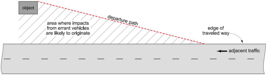
Figure 1: Concept of the departure path.
The departure path is an estimate of the longest route that an out-of-control vehicle could follow and still be expected to impact the object, prior to stopping. The location of this path directly affects the length of barrier needed to shield an object. Therefore, establishing an appropriate departure path is a critical step in the barrier design process.
The departure path is assumed to be a straight line, and it is defined by two variables: lateral extent of the object, and runout length.
Lateral Extent of the Object (\(L_A\))
Lateral extent is the distance from the edge of traveled way tothe far side of the object, or the design clear zone distance (see Section 8A-2), whichever is smaller. As shown in Figure 2, the LA for object 1 extends to the far side of the object. However, the LA for object 2 is limited by the design clear zone distance.
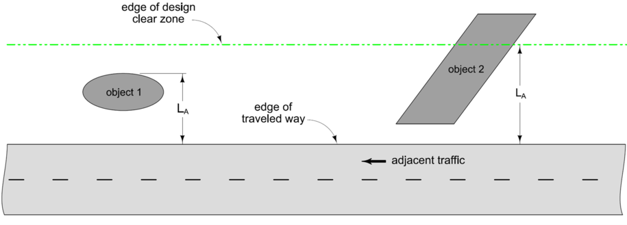
Figure 2: Comparison of \(L_A\) distances for different objects.
Runout Length (\(L_R\))
Runout length is the distance measured along the roadway from the upstream extent of the obstruction to the point at which a vehicle is assumed to leave the roadway. Runout length is based on design speed and traffic volume, and is determined using Table 1.
Once \(L_A\) and \(L_R\) are determined, the departure path can be established graphically (refer to Figure 3):
- Identify the location where the object warrants protection, for example, the leading edge of a fixed object or where a slope first becomes hazardous.
- Draw a line from this point toward, and perpendicular to, the centerline. The intersection of this line with the edge of traveled way marks the beginning of the runout length.
- Scale off the runout length along the edge of the traveled way, working upstream from the object.
- Draw the departure path by connecting the end of the runout length to the leading, far side edge of the object (or the edge of the clear zone, whichever is less).
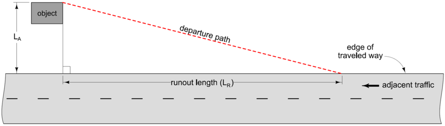
Figure 3: Establishing the departure path.
Departure Path for Opposing Traffic
A departure path is established for each object within the clear zone of adjacent traffic. For objects that are also located within the clear zone of any opposing traffic, the process is completed twice – once for the adjacent traffic, and once for the opposing traffic.
Consider the situation shown in Figure 4. Note that the edge of traveled way for opposing traffic in this case is the painted centerline. Therefore, the \(L_A\) distance and departure path originate from this line.
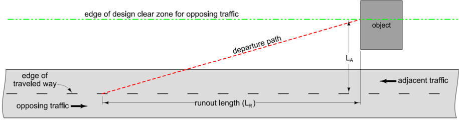
Figure 4: Departure path for opposing traffic.
If opposing traffic is separated by a median, the edge of traveled way for opposing traffic is the inside edge of the opposing travel lane.
Effect of Curvature on Departure Paths
All previous examples of establishing departure paths have assumed a straight roadway. In practice, however, many objects are located on or near curved roadways. The effect of roadway curvature varies depending on the degree of curvature and whether the object is located on the outside or inside of the curve.
Objects on the Outside of a Curve
Vehicles leaving the roadway on the outside of a curve can be expected to follow a path that is tangent to the curve. Such a path may vary from the path assumed for a straight roadway. Therefore, the departure path for this situation must be determined and compared to the departure path based on the runout length (refer to Figure 5):
- Draw the departure path using the process described previously. However, when scaling out the runout length, make sure to follow the curvature at the edge of traveled way.
- Draw a line from the leading, far side edge of the object (or the edge of the clear zone, whichever is less) to a point on the edge of traveled way that is tangent to the curve. This line defines the tangential departure path.
- Compare the two departure paths. Use the one that is shorter.
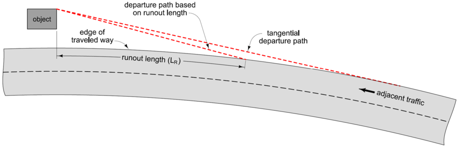
Figure 5: Departure paths on the outside of a curve.
Objects on the Inside of a Curve
Follow these steps to establish the departure path for an object located on the inside of a curve (refer to Figure 6):
- Locate the point at the leading, far side edge of the object (or the edge of the clear zone, whichever is less).
- Using this point as the center, draw an arc with a radius of LR.
- Draw a line from the far side of the object (or the edge of the clear zone) to the point where the arc intersects the edge of traveled way. This line defines the departure path.
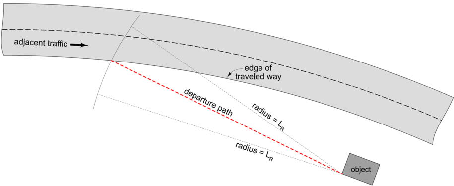
Figure 6: Departure path on the inside of a curve.
Effect of Object Shape and Orientation on Departure Paths
Most objects used in the previous examples have been rectangular shaped and oriented parallel to the roadway, making the establishment of departure paths relatively straightforward. However, the shape and orientation of objects in the field varies widely. Selecting appropriate departure paths for such objects requires further examination.
Take, for example, the object shown in Figure 7. Assuming point 1 is a point of concern on the object, the LA distance at point 1 can be combined with the runout length to establish a vehicle departure path into point 1. However, point 2 could also be considered a point of concern on the object. The LA distance at point 2 can be combined with the runout length to establish a vehicle departure path into point 2.
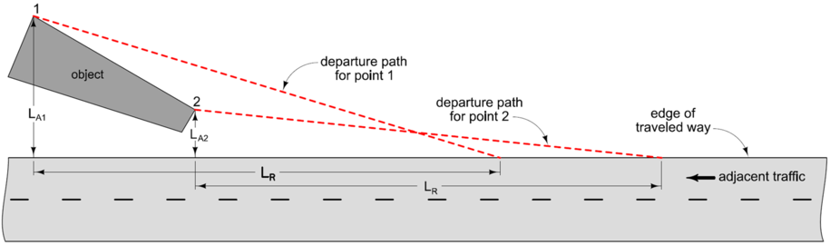
Figure 7: Departure paths for skewed or irregularly shaped objects.
There is no way of knowing which of the two paths better describes how an errant vehicle might impact the object. To account for this, the paths must be combined. A composite departure path is formed by combining the outer limits of each individual departure path, as shown in Figure 8.
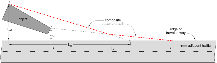
Figure 8: Defining a composite departure path.
This same process is used when defining a departure path for multiple objects that are located within close proximity to each other, for example, a bridge rail end section and the nearby stream bank.
Back to topLength of Need
The minimum length of a barrier needed to protect the approach end of an object is called the length of need. The departure path serves as a basis for determining the length of need. As shown in Figure 9, a barrier placed in front of an object that is long enough to intersect the departure path would be expected to shield the object from most potential impacts. Also consider the following:
- Motorists leaving the traveled way at the end of the runout length, but at an angle sharper than the departure path, should not be able to reach the object.
Motorists leaving the traveled way upstream of the end of the runout length should have sufficient opportunity to slow or stop their vehicles prior to reaching the object.
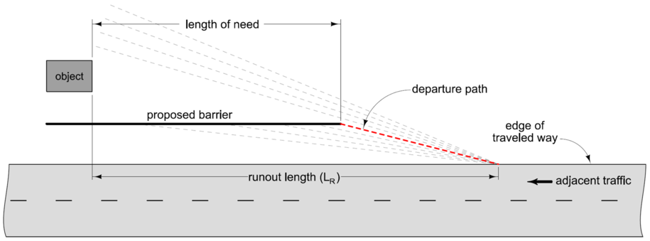
Figure 9: Theory behind length of need.
Offset from the Traveled Way
The offset of a barrier from the edge of traveled way has a impact on the length of need for that barrier. In Figure 10 each of the proposed barriers intersects the departure path and therefore adequately protects the object. The farther a barrier is located from the edge of traveled way, the shorter the barrier can be.

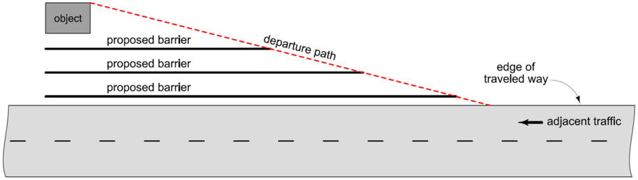
Figure 10: Effect of barrier offset on length of need.
Choosing how far to offset a barrier from the traveled way is somewhat of a balancing act. On one hand, placing a barrier as far from the road as possible is preferred. This makes impacts into the barrier less likely, because it provides a wide area for errant motorists to regain control and stop their vehicles prior to impacting the barrier. Such a placement can also result in a maintenance cost savings, since fewer impacts means less frequent repairs.
On the other hand, placing a barrier far from the road may be less preferable because it tends to increase installation costs. Since most barriers must be installed on relatively flat slopes, the amount of earthwork required might increase significantly. Also, an out-of-control vehicle that happens to reach the barrier may impact it at a sharper angle than usual, which could increase the severity of such a crash.
A good compromise in most cases is to locate the face of the barrier 2 feet beyond the edge of the normal shoulder. This places the barrier close enough to the pavement that earthwork will not be excessive, yet far enough from the traveled way that the likelihood of impacts into the barrier is reduced. However, alternative offsets may be used depending on site conditions and the type of barrier chosen.
For example, in areas with steep slopes, it may be preferable to place the face of the barrier even with the edge of the shoulder to minimize earthwork requirements. In locations with restricted widths, such as at bridge underpasses, barrier placement on the shoulder may be the only alternative to provide the necessary deflection distance behind the barrier. However, if placing a barrier on the shoulder reduces the effective shoulder width (see Section 3C-4) to less than the minimum width allowed for a project, this must be documented according to Section 1C-8.
Flare Rate of the Barrier
Flaring a barrier can greatly effect the length of need for that barrier, see Figure 11. Each of the proposed barriers intersects the departure path and adequately protects the object.
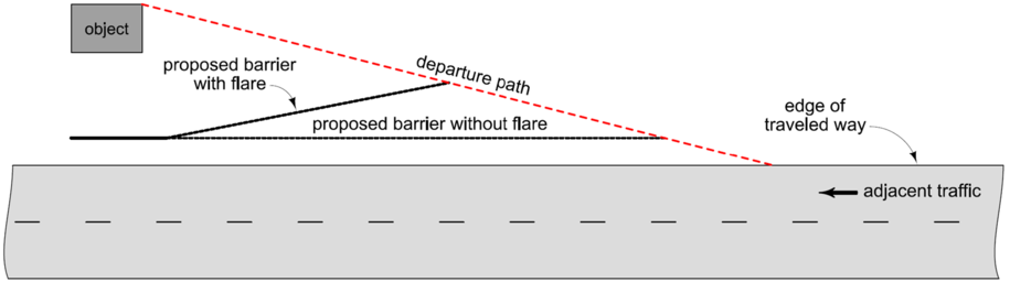
Figure 11: Effect of barrier flare on length of need.
While flaring a barrier does reduce its length of need, it also increases the angle at which an errant vehicle might impact the barrier. Because this can increase the severity of an impact, flare rates of barriers are limited depending on the type of barrier being used. For a discussion of allowable flare rates for a certain barrier, refer to the section of this manual that covers that particular barrier type.
Back to topTerminating a Barrier
To adequately protect an object, the length of need portion of a barrier must be of a crashworthy design, such as those shown in the BA Series Standard Road Plans. This portion of a barrier is meant to withstand impacts from the side, but not necessarily at the end. Therefore, if a barrier terminates within the clear zone of any approaching traffic, it must include a crashworthy end treatment.
An object being shielded for adjacent traffic might not be within the clear zone for opposing traffic, but the barrier often is. Therefore, if the downstream end of a proposed barrier installation is within the clear zone of any opposing traffic, that end of the barrier must also be terminated with a crashworthy end treatment (see Figure 12).
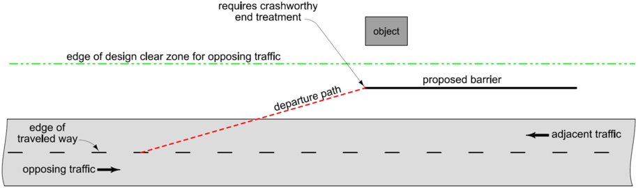
Figure 12: Barrier located within clear zone of opposing traffic.
Gaps between Barrier Installations
Numerous barrier installations may be required along a given roadway. The ends of barriers are the most critical and require the most maintenance when impacted. Therefore, the number of barrier ends should be minimized whenever possible.
Gaps of 200 feet or less between individual barrier installations should be eliminated by extending the barrier through the intervening gaps, resulting in one continuous barrier shielding two or more objects.
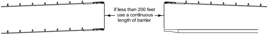
Figure 13: Examples of gaps between barrier installation.
Short gaps often occur because the locations of existing barrier installations are either unknown or are not considered. In other cases, gaps occur because objects that warrant barriers, such as bridges and overhead sign trusses, are constructed as part of the same project, but under different contracts. Therefore, seek to identify the locations of both current and future objects so that barrier designs are coordinated and short gaps are avoided.
Back to topChronology of Changes
Back to top