Content Information
On this page...
Overview
Public Involvement Definitions
A Public Information Meeting, (PIM), is a forum to solicit input from or provide information to the public on a proposed project. A summary of the meeting may be completed after a Public Information Meeting, rather than a transcript.
A Public Hearing, (PH), is a meeting where Iowa DOT officials hear the public's views and concerns about a proposed project. A Public Hearing is always conducted for a project involving an environmental impact statement or environmental assessment, and generally for a project when it is anticipated there will be a condemnation of agricultural land and compliance with Code of Iowa chapter 6B is required. A meeting transcript is made available after a Public Hearing.
Display Description
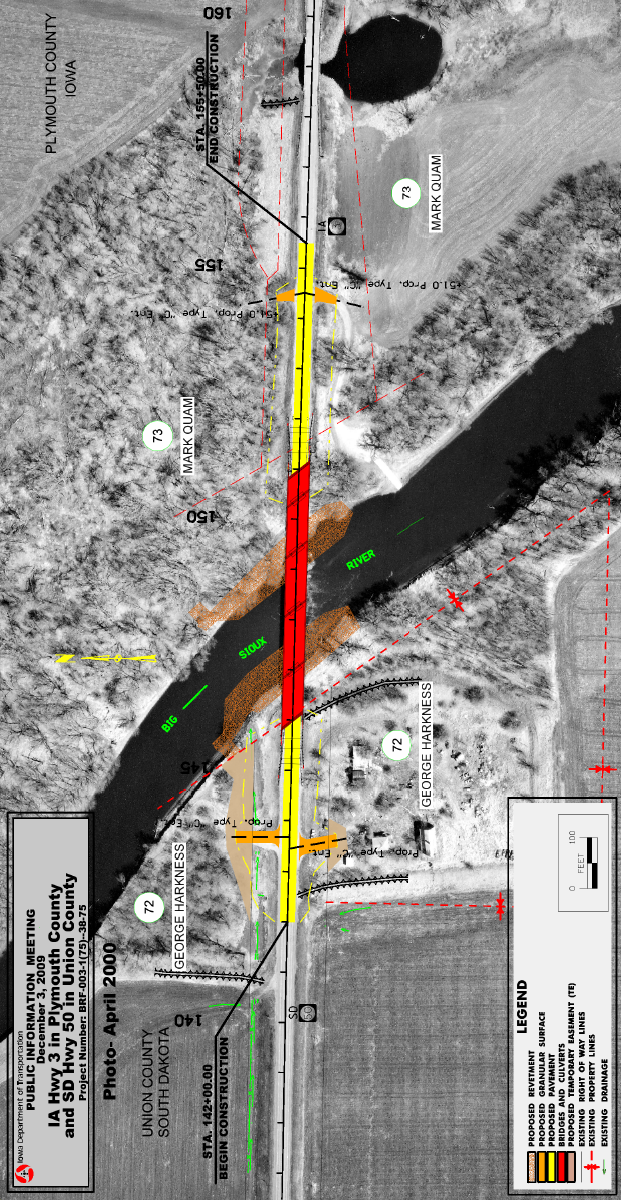
A design Public Involvement (PI) display is a CADD-generated color drawing, preferably on a photo background, used to present design and Right of Way details for the proposed project. The display is presented on paper to the general public at informational meetings and public hearings. The display will also be available on the Project Web site. For presentations to the Commission or department staff, the display may be projected electronically or presented on paper. The display contains only the information that is relevant for understanding the general layout of the project. Detour maps, noise walls and aesthetics are examples of other types of exhibits used at public involvement events.
Preparation of design public involvement displays requires coordination between the Office of Right of Way (ROW), the Office of Design (Design), the Office of Location and Environment- Public Involvement Section (OLE-PI Section), the District Office (District), and possibly others, including Bridges and Structures.
The department goal is consistency between the various types of displays for the various meetings; e.g. a detour map for one project should resemble a detour map for other projects, and aerial displays should have the same base elements for all projects, etc.
Back to topOffice obligations
Office of Right of Way (ROW)
As soon as the R1 event (Right of Way Layout) is complete, ROW provides copies to the District. Copies of the plan are also made available to the OLE-PI Section, which is responsible for scheduling the Public Involvement (PI) event. ROW shall inform Design when the R1 event occurs so Design can access the current right-of-way information. This ensures that Design and the District have the same information. (For additional information, see the Automation Process portion of this document.)
ROW is also responsible for all right-of-way information on the PI display. ROW personnel will create translucent colored, filled shapes for permanent acquisitions and temporary easements and will place appropriately scaled and orientated property owner names and parcel numbers.
Office of Design (Design)
Design is responsible for the remainder of the display preparation and will create filled shapes for pavement, paved medians, bridges, culverts, and other design features.
As soon as the display is complete, Design shall notify the PI Section, ROW and the District so the display can be reviewed by all appropriate offices.
Back to topDeadlines
Display Review – Three weeks prior to PI Event
Approximately three weeks prior to the PI event, ROW, Design, the District, and the PI Section will meet to review the display. Design will organize this meeting. All offices and personnel involved must work together to have a successful PI Event.
Stop Changes to Plans - Two weeks prior to PI Event
A “stop work” date will be set two weeks prior to PI Event. This means that during the two-week period prior to the event, no change affecting right-of-way will be allowed in any file being used for the display, unless ROW agrees to the change. Right-of-way limits can be affected by many things, including, (but not limited to), changes to alignments, need lines, entrances, ditch widths, foreslopes, driveways, etc. Changes that do not affect right-of-way are allowed. Agreement from ROW is critical, so that Design and ROW attend the PI event with the same plans. Consistency and communication among offices is crucial for a successful PI event.
Print Display – Two weeks prior to PI Event
Two weeks prior to the event date, Design will print the exhibits. ROW and Design will also print plans to be used for the event. This will include plan and profile sheets and cross sections. If alignment changes were permitted by ROW after the “stop change” date, the plan and profile sheets and the roadway cross section sheets, (in the Public Involvement folder, located directly under your Design folder), should be updated to reflect the changes. Coordination between ROW and Design is required to ensure the plans from both offices are identical.
Post the Display to the DOT Web site – Two to three days prior to PI Event
At this time, a link to the final PDF files used for the PI display should be provided to the Web team, (username “DOT-WebTeam”), so the files can be displayed on the DOT Web site. This information should also be cc’d to the PI Section, (who are members of the “dsnPublicHearing” user group). See below for more details.
Back to topDisplay Development
Features Included
All PI displays should have an aerial photography image background. Low flight aerials, with a high level of detail, are preferred.
There are some project features that may require a separate display for adequate representation:
Off-site detours
On-site detours of a complicated nature
Enlargements of Critical Areas of a project
Off-site borrows
Off-site haul roads
Mitigation sites
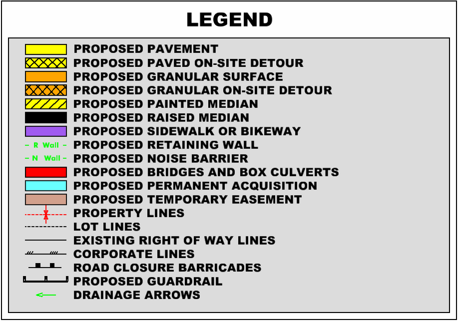
The following table lists the proposed features included on a PI display, and the associated color used to represent each feature. (For a graphic display, see the sample legend shown later in this document.)
| PI Display | Color name & number (hwyclr.tbl) |
|---|---|
| Proposed pavement | Yellow (4) |
| Proposed paved on-site detour | Yellow (4) with black crosshatch (0) |
| Proposed granular surface | Orange (6) |
| Proposed granular on-site detour | Orange (6) with black crosshatch (0) |
| Proposed painted median | Yellow (4) with black diagonal (0) |
| Proposed raised median | Black (0) |
| Proposed sidewalk or bikeway | Purple (111) |
| Proposed retaining wall | Light green (146) with R Wall text |
| Proposed noise barrier | Light green (146) with N Wall text |
| Proposed bridges | Red (3) |
| Proposed culverts | Red (3) |
| Proposed permanent acquisition | Blue (119), 40% transparency |
| Proposed temporary easement | Tan (40), 40% transparency |
| Property lines | Red dashed line (3) |
| Ownership boundary symbol | Red arrows (3) |
| Lot lines | Black dashed line – light (0) |
| Existing ROW lines | Black solid line – heavy (2) |
| Corporate lines | Black line (0) |
| North arrow and scale | Black (0) |
| Road closure barricades | Black (0) (cell) |
| Proposed guardrail | Black line with symbols (0) (cell) |
| Drainage arrows | Green (2) |
All other design features shall be black. Survey features that are needed, (Photogrammetric or Field), shall be shown in green, unless indicated otherwise, above.
Text included on displays
The text on the display, like the proposed features, should be limited to information required for a clear understanding of the geographic layout of the project. All text shown on the display shall be black. The following text should be included:
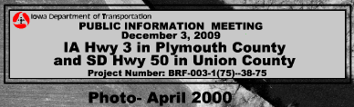
Title of the display: This includes the county name, project number, and the date and type of the public involvement event. From the PubHearing cell library, use either the Titleblock_PIM or Titleblock_PHM cell, (shown below), to be placed at the upper left corner of the display.
The Date of the aerial photography background should be shown as a month and year, and should be located directly below the Title of the Display, as shown above.
The Legend is to be placed at the lower left corner of the display. The Legend cell, (shown), contains an example of nearly every element and shading type and color that could be present. The items that do not relate to the project should be removed from the Legend and the Legend size reduced accordingly. The Legend should be placed once for approximately each six feet of display.
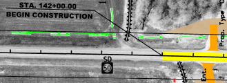
The Project Limits labeling for mainline and side roads includes labeling the mainline with stationing and “Begin Project / End Project” notes, and labeling the side roads with stationing only.
Previous and future projects: If other projects tie to the display project, the roadway should be shown with a dashed outline and a label of either “Future Project” or “previously discussed project.”
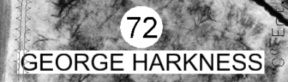
Property owner names and parcel numbers: (This information comes from the ROW file)
Permanent acquisitions already purchased: If there have been early property acquisitions, the owner should be listed as the “State of Iowa”, with the prior landowner’s name in parenthesis. (This information comes from the ROW file).
Mainline roadway name, i.e.: “Proposed U.S. 34” or “Existing U.S. 34”
Include labels for streams, rivers, other named waterways and other streets. For the roadway labels use a combination of the federal, state, or county route symbol and number, followed by the “911” or “street sign” name in parenthesis, (use the cell library highway symbols),
Roadway stationing: Label the centerline stationing at 500 foot increments.
Borrows: Label the borrow type as either “drainable” or “pond.” Confirm the borrow type with Soils before printing.
Haul roads: Label the haul road if in close proximity to the project. (If off site, it will be a separate display.)
Proposed roadway closures / obliterations labels, including closed entrances and crossovers in the access control areas only.
Mitigation site labels, if finalized.
Corporate limit labels.
Items that should NOT be shown on the display
All other text (ie: horizontal curve data, culvert data, bridge text, utility text), should not be included
Center section symbols
Temporary easement notes
Water valves, intakes, electric and telephone lines, tile lines, etc.
Outline of the limits of the proposed right of way
Ground Intercept lines
Right of way symbols, such as open or filled triangles and hexagons
Types of ownership, such as ¼. ½. Life estates, etc.
Existing pipes
Township, Section and Range information
Cultural and archeological sites should not be shown. For historical sites, contact the Cultural Resources Section of the Office of Location and Environment for a final decision concerning the appearance on the display.
Other display considerations
For ROW PI displays, also include the total parcel ownership, if coverage is available, and station callouts. (The addition of the station-callouts on a ROW display is a difference between a ROW display and a Design display with ROW information.)
Below are a few special cases and how they are to be handled:
On four lane divided highways, the crossovers will be shown at both access locations and Future Access Locations.
Property lines should not be shown extending to the centerline of the roadway or to the section line, as per ownership deeds. Instead, show the property line extending to the existing right of way line. The existing right of way line, adjacent to the roadway, will also be shown as a property line.
The north arrow, legend, and title should be placed one time on each 6 feet of display length, and at least once on each separate scroll, using a double black border on a gray shaded block.
The scale should be either 1 inch = 20 feet, or 1 inch = 50 feet for urban projects, and 1 inch = 100 feet for rural projects. For metric projects, the scale should be either 1:250 or 1:500 for urban, and 1:1000 for rural.
All construction elements, such as proposed pavement, bridges, structures, granular surfaces, sidewalks, retaining walls, and temporary pavement, should be opaque. All right of way acquisition and easement elements should be translucent.
Proposed culvert shapes should be displayed “under” the proposed roadway shapes.
When corporate lines, property lines, drainage arrows or text are not adequately legible when displayed against a dark portion of the aerial photography background, the “halo effect” text should be used with white. (The “halo effect” tool can be found in D&C Manager under Design Files > Public Hearing (.pub) > Plan View > Halo Placement.)
Display Preparation – Automation Process

| NOTE: Because a PI Display may be presented numerous times, it is important that the same final display (PDF file) is presented each time, regardless of any changes made to the Design and ROW working files between presentations. |
|---|
The steps listed below describe the general process to be used when creating a PI display. Following these steps should ensure that the same information is displayed at each presentation.
Design should create a “Public_Involvement” folder under the Project Directory “Design” folder to hold all PI related files and information, including the design file(s) and the PDF file(s). See example at the right.
The PI meeting display file will be created from a new 2D MicroStation file, created in the Public_Involvement folder.
(If multiple files and/or displays are created for any given section or project, separate “dated” sub-folders should be created under the main Public_Involvement folder. This may be due to more than one public meeting for a given section.)
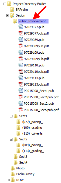
The name of a “project” PI display file will be generated using the county number (C), route number (R), and the project number parenthesis number (P), and the file extension of “.PUB”: CCRRRPPP.PUB. File names for “Corridor” or “Section” PI meeting displays may be named using the PE number, as shown at the right. From this point forward, the Design PI display file will be referred to as the Design .pub file.
All MicroStation models required for the PI display should be attached to the Design .pub file as references. There will probably be several models referenced from the Design .dsn file, as well as models from the Photogrammetry .pho file, Survey .sur file, and the ROW .row file.
Create filled shapes and place the fence plot outlines (shapes) in the Design .pub file.
Copy the necessary elements, (such as north arrow, scale blocks, etc.), into the Design .pub file. Scale and/or rotate them as necessary so they are oriented correctly to match the plotting outlines. (The Copy, Rotate & Scale command will work well for this task.)
After the “Stop Work” date, (formerly referred to as the “lock” date), Design should create the PDF files for all PI displays. Since PDF plot files are static, no future changes to any of the files associated with the project will affect the PDF files. (See NOTE below.)
Plot the PI display to paper, as necessary.
|
| NOTE: The PI Display PDF files shall be maintained for historical reference. |
|---|
After the print scroll is ready and the final printing is complete, send an email to the “DOT-WebTeam” and also “cc” the members of the OLE-PI section, (who are members of the “dsnPublicHearing” user group). The email should include the link to the location of the scroll file and any other display files to be used at the PI event. The County, Route, and Date of Meeting should also be included in the email.
Chronology of Changes
| Date | Revision Description |
|---|---|
| 6/30/2011 | Updated to current method |
| 12/31/1997 | Originally Issued |