Content Information
On this page...
BA 100s
Barriers – Concrete Barriers
As noted in Section 8A-4, BA-108 should be used only in areas where posted speed limits are 30 mph or less. For posted speeds 35 mph or greater, use guardrail or a crash cushion. Situations will arise where constraints may not allow for the use of guardrail or crash cushion in an area with a posted speed greater than 30 mph. Contact Roadside Safety for assistance.
Back to top
BA 200s
Barriers - Steel Beam Guardrail
See Section 8C-2 for general design information regarding steel beam guardrail design.
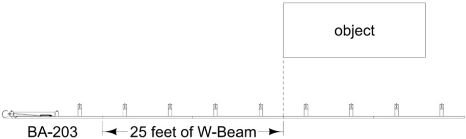
BA-203 Steel Beam Guardrail W-Beam End Anchor
- Use only outside of the clear zone for approach traffic, see Section 8C-2.
- An extra 25 feet of guardrail should be added beyond the trailing end of an object to allow the end anchor to develop full strength if impacted, see Figure 1.
- Do not use with a W-beam to cable crossover without first contacting Roadside Safety.
BA-204 Steel Beam Guardrail Thrie-Beam End Anchor
- Use only with Steel Beam Guardrail Installation at Railroad Signal (BA-253).
- Do not use with a W-beam to cable crossover.
BA-205 and BA-225 Steel Beam Guardrail Tangent End Terminals
- Previously, the dsnGuardral.cel library had two cells for the BA-205: MGS_Term_on_Flare and MGS_Term_on_Tangent. These have been replaced with one cell: MGS_Term_BA-205. A new end terminal cell has been created: MGS_Term_BA-225.
- Two additional new cells have been created for the dsnGuardrail.cel library: MGS_VT_to BA-205_or_BA-225 and MGS_VF_to BA-205_or_BA-225. These transition cells are placed immediately downstream of the end terminal, see Figure 2.
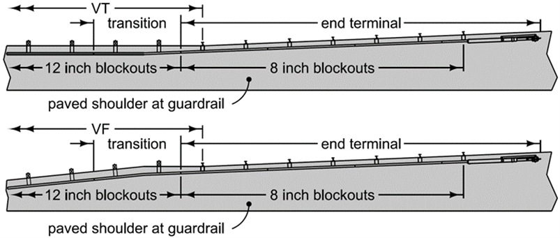
- These cells serve two purposes:
- To transition from variable tangent (VT) or variable flare (VF) to BA-205 or BA-225.
- To set up the pavement edge transition from the 12-inch blockouts of the VT and VF to the 8 inch blockouts of the BA-205 and BA-225.
When transitioning from VT to an end terminal, the transition is included in the VT. When transitioning from VF to an end terminal, the transition is included in the VF.
BA-209 Steel Beam Guardrail Barrier Transition Section MASH TL-3, 34 inch mounting height
- Use only with Bridge Standard Sheets 1017-1 and 1017-2, Barrier End Section.
- A symmetrical Thrie-Beam to W-Beam transition section is used.
BA-211 Steel Beam Guardrail Long-Span System for Post Conflicts:
- Clear area behind rail expands as posts are removed. Expand clear area before placing crashworthy and breakaway objects behind the rail according to the following as measured from the face of rail:
- Standard guardrail: 5 feet per Section 8C-2
- Type 1: 6 feet
- Type 2: 7 feet
- Type 3: 8 feet
- Within this expanded area, there is a maximum object height of 2 inches.
BA-221, BA-225, and BA-260 MASH TL-2 Standards:
- Contact Roadside Safety prior to use.
- May be used where posted speeds are 40 mph or less or ADT is 400 vpd or less.
- May be used where standard guardrail lengths for a MASH TL-3 system cannot be achieved due to constraints.
BA-253 Steel Beam Guardrail Installation at Railroad Signal
- Do should be a minimum of 2 feet.
- Face of guardrail should preferably be a minimum of 5 feet from signal footing.
High Tension Cable Guardrail to Steel Beam Guardrail Connection
- See Section 8C-3 for design information.
- Include bid item for Guardrail, Special Anchor System.
If you have any questions or problems, contact Roadside Safety.
Back to top
BA 300’s
See Section 8C-3 for design information.
Back to top
BA-500
Temporary Crash Cushions - Sand Barrel Details
See Section 8C-5 for design information.
Items to note about this standard:
The embankment shown on Sheet 1 may not be required when sand barrels are installed on pavement or on wide shoulders. If not required, mark dashes in the associated columns of Tabulation 108-30.
The sand barrel layout shown on Sheet 2 is the only approved layout.
The last barrel in the layout must be offset at least 30 inches in front of the face of the obstacle.
Some common situations where sand barrels are used are shown on Typicals 8210 and 8212, and Standard Road Plans TC-217 and TC-421.
Back to top
BR's
Bridge Approach Pavement
Contact the Office of Bridges and Structures for the type of approach and abutment to use.
Double reinforced bridge approach paving (BR-200s) is used for Primary Road System bridges. A 12 inch approach should be used for new construction. A 10 inch approach should be used only if replacing an existing 10 inch approach. Use of double reinforced bridge approach paving is encouraged for Secondary Road System bridges. If the need arises for the double reinforced section to be longer than the 20 foot minimum shown on BR-201, BR-202, BR-203, and BR-204, contact the Bridges and Structures Bureau to verify location of the lug for movable abutments.
Use of single reinforced bridge approach paving (BR-100s) should be limited to Secondary Road System bridges. Single reinforced bridge approach paving may be used as replacement-in-kind for Primary Road System bridges on lower volume roads.
Removal of existing bridge approach pavement is not incidental to the placement of new bridge approach pavement. Calculate and bid the removal quantity as a separate item.
For BR-205, the sleeper slab is added into the quantities for the double reinforced section. To do this, add 8 feet (1.75 feet (width of top portion of sleeper slab) + 6.25 feet (width of portion of sleeper slab under the pavement)) to the double reinforced section and calculate square yards.
For BR-241, Special Backfill is used instead of Modified Subbase.
Back to top
DR-101
Pipe Culvert (Bedding and Backfill)
Calculate excavation and backfill quantities based on Section 5B-2.
For situations where water from flooded backfill cannot drain (e.g. staged pipe, utilities), add the following note to the remarks column of Tabulation 104-3:
In trench installations, replace floodable fill with Class ‘A’ road stone compacted according to Section 2416 or 2417 of the Standard Specifications.
For utilities and storm sewer under the roadway, refer to SW-101.

| Pipe elongation (when specified) is done in the vertical direction to counter deformation caused by backfill. It is not to be used to widen a pipe horizontally to form an elliptical pipe. |
|---|
Back to top
DR-111
Box Culvert (Backfill)
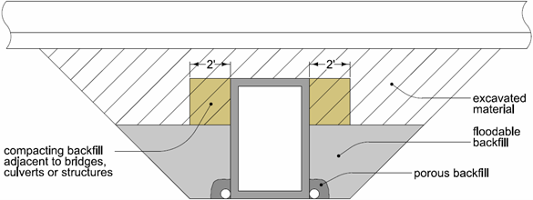
Calculate excavation and backfill quantities based on Section 5B-2. DR-111 indicates 5 feet minimum of floodable backfill. This means designers should base the height of floodable backfill at no more than 5 feet. Note 1 in DR-111 allows contractors to use floodable backfill above this 5 foot height, but they are not allowed additional compensation.
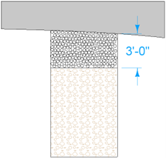
The bid item for Compacting Backfill Adjacent to Bridges, Structures, Culverts or Structures covers the expense for the extra effort required to do the compaction, not the material. The material used is simply the excavated material used for backfill and is accounted for in that quantity. Compacting Backfill Adjacent to Bridges, Structures or Culverts is calculated from the top of the floodable backfill to the top of the culvert, see Figure 1.
If there is removal of an existing box culvert that is offline of the alignment of the new culvert, bid either additional flooded backfill (5 feet minimum, see DR-111) or additional Compaction with Moisture Control for the area of removal. Include a note in Tabulation 104-4.
Back to top
DR-305
Subdrain Outlets (Standard Subdrain, Pressure Release and Special)
For Type A and B installations, DR-306 should be used if the outlet could be run over by machinery; otherwise, Design Detail 500-10 can be used. For Type B installations, use Design Detail 500-10 if the outlet could be submerged by water running in the ditch potentially causing a concrete headwall (DR-306) to wash out. For Type C installations, use Design Detail 500-10.
Back to top
DR-306
Precast Concrete Headwall for Subdrain Outlets
The DR-306 is the default outlet for longitudinal, transverse, and backslope subdrains. In some situations, Design Detail 500-10 may be used. For more information regarding its use refer to the Designer Info of Design Detail 500-10.
Back to top
DR-401
Scour Protection for Bridge End Drain
Refer to Section 4C-2 for more information pertaining to bridge end drains. Refer to Section 7D-1 for information pertaining to determining reinforced bridge approach section dimensions.
|
| Circle note 2 instructs the contractor to continue the 4 inch sloped curb to the edge of the flume. Verify the curb drop does not occur within the BTS or the end terminal for barrier rail (refer to BA standards). If it does, relocate the flume so the curb drop does not occur within the BTS or end terminal. |
|---|
In situations where the design calls for a flared shoulder panel, move the flume down the foreslope to maintain a minimum length of 4 feet of scour protection adjacent to the shoulder panel. This will create a situation where there is an additional triangular shape of scour protection adjacent to the shoulder panel.
Back to top
DR-402
Rock Flume for Bridge End Drain
Refer to Section 4C-2 for more information pertaining to bridge end drains. Refer to Section 7D-1 for information pertaining to determining reinforced bridge approach section dimensions.
|
| Circle note 2 instructs the contractor to continue the 4 inch sloped curb to the edge of the flume. Verify the curb drop does not occur within the BTS or the end terminal for barrier rail (refer to BA standards). If it does, relocate the flume so the curb drop does not occur within the BTS or end terminal. |
|---|
In situations where the design calls for a flared shoulder panel, move the flume down the foreslope to maintain a minimum length of 3 feet of macadam stone adjacent to the shoulder panel.
Back to top
DR-501
Corrugated Metal Type ″A″ Diaphragm
Diaphragms are shown Standard Road Plans DR-631, DR-632, DR-642, and DR-652. They are used with CMP letdowns to eliminate piping of material if flow were to migrate between joints or undermine the culvert. They are an additional safety feature used to mitigate future piping or erosion.
DR-631, Corrugated Pipe Culvert Letdown Structure with Single Elbow
Assume 2 diaphragms unless indicated otherwise by Preliminary Bridge.
DR-632, Corrugated Pipe Culvert Letdown Structure with Double Elbow
Assume CMP will be used. Assume 1 diaphragm unless indicated otherwise by Preliminary Bridge.
DR-642, Apron Pipe Tee Inlet
Assume CMP will be used. Assume 1 diaphragm unless indicated otherwise by Preliminary Bridge.
DR-652, Unclassified Letdown Structure Single Elbow
Assume CMP will be used. Assume 2 diaphragms unless indicated otherwise by Preliminary Bridge.
Back to top
DR-504
Diagonal Placed Drain for Median Crossovers
Adjustments to removal depth may need to be made for topsoil requirements. Refer to Section 10A-1 for additional information.
For short durations (placement and removal within one construction season), placement of special backfill is recommended underneath the drain. For longer durations, consider switching to class 10.
Back to top
DR-622
Pipe Extension Horizontal Bend One or Both Ends
Determining Skew Ahead is different than for a culvert. Rather than being based on the roadway alignment, skew for a pipe extension is based on the centerline of the structure, i.e. as if you are looking through the pipe.
Back to top
EC-104
Turf Reinforcement Mat
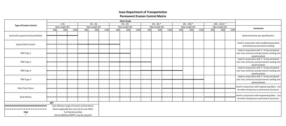
Turf Reinforcement Mat (TRM) types are described in Article 4169.10, E of the Standard Specifications. Use the attached Permanent Erosion Control Matrix to determine which type of TRM to use in channel applications such as ditches. For slope applications, Type 1 and Type 2 are used on 1:1 or flatter slopes and Type 3 and Type 4 are used on 1:1 or steeper slopes. Contact the Agronomist with additional questions regarding choosing which type of TRM to choose.
Back to top
EC-201
Silt Fence
Silt Fence
Refer to Section 10C-1 for guidance on bid item quantities.
Refer to Section 10C-2 for more information regarding Silt Fence for Ditch Checks used for storm water detention.
When rolled erosion control products are used in ditches and medians, use perimeter and slope sediment controls for ditch checks instead of silt fence. Perimeter and slope sediment control products do not require cutting the rolled erosion control product.
Notes 5 and 6 provide equations to use to calculate the end span on the foreslope and backslope. The idea is to run the silt fence up the foreslope and backslope to the point where the top of the silt fence in the ditch is below the bottom of the silt fence on the foreslope and backslope. To be conservative (and to simplify calculations), the silt fence is assumed to be 2 feet tall, thus the end span is simply 2 × foreslope or 2 × backslope. For a 6:1 foreslope, the minimum end span is 2 × 6 = 12 feet.
Silt Fence Installation for Shallow or No Ditch
These installations address two situations: ditches shallower than 19 inches, and no ditch situations.
Shallow Ditches
This is based on the height of the silt fence being 19 inches. If a ditch is less than 19 inches deep, stormwater could pond deep enough to flow around a silt fence ditch check.
No Ditch
This standard is also used for no ditch situations. A run of longitudinal silt fence runs approximately parallel to the toe of the forslope to capture stormwater.
For both shallow ditch and no ditch situations, if the ditch grade (shallow ditch situations) or grade along the toe of foreslope (no ditch situations) is less than 0.5%, place a run of silt fence 5 feet parallel to the shallow or no ditch installation to capture stormwater that could run around the end of the installation. An additional run of silt fence is always placed at the right-of-way line.
Note 3 provides an equation to use to calculate the end span on the foreslope. The idea is to run the silt fence up the foreslope to the point where the top of the silt fence in the ditch is below the bottom of the silt fence on the foreslope. To be conservative (and to simplify calculations), the silt fence is assumed to be 2 feet tall, thus the end span is simply 2 × foreslope. For a 6:1 foreslope, the minimum end span is 2 × 6 = 12 feet.
Situations may arise where plans and/or GoogleTM earth don’t clearly define the drainage pattern for a basin (e.g. along a no-ditch area). In cases such as these, designers will need to assume the basin flows to some type of drainage channel or structure.
Erosion Control for Trenchless Construction
This installation is used to place silt fence around spoils from pits for jacking pipes. The trenchless construction is bid as a separate item. This detail only requires the silt fence to be bid. Since the size of the pile of spoils is not known, bid 250 feet of silt fence.
Designers do not need to calculate stormwater volumes for this installation.
Back to top
EC-202
Floating Silt Curtain
Refer to 10C-1 for guidance.
Back to top
EC-204
Perimeter and Slope Sediment Control Devices
Refer to Section 10C-1 for guidance related to use of Perimeter and Slope Sediment Control Devices and bid item quantities. As noted in Section 10C-1, when these devices are used in ditches, designers should add in the estimate reference note that 20 foot logs are to be used.
When used as inlet perimeter protection, a 12 inch device is typically used.
Back to top
EC-301
Rock Erosion Control (REC)
Rock ditches (TYPE 2) are typically used when a high flow rate is expected, e.g. in areas of steep ditch grades. W is 6 feet wider than the ditch bottom. For a standard 10 foot wide ditch bottom, W is 16 feet.
Rock flumes (TYPE 3) are intended primarily for use on backslopes because higher flow or higher sediment rates are expected. They can also be used on foreslopes. However, if placing a rock flume as a bridge end drain, use DR-402.
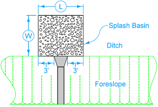
Splash basins (TYPE 4) are required at all bridge drains and at all cross road culvert outlets.Typically, designers size splash basins for pipe culvert outlets. Normally, L is the width of the apron at the outlet plus 6 feet (see the figure below from EC-301), and W is the same as L.
Back to top
EC-302
Rock Check Dam
Rock check dams are typically used where silt fence ditch checks have failed. Sections 10C-1 and 10C-2 provide more information regarding use of and tabbing rock check dams.
Back to top
EC-303
Stabilized Construction Entrance
Refer to Section 10C-1 for guidance.
Back to top
EC-601
Temporary Sediment Control Basin
Temporary Sediment Control Basins are typically used for drainage basins 10 acres or larger, where they are required. They are also used as a supplement to silt fence ditch checks, rock check dams, and silt basins if those devices don’t provide enough storm water storage volume. Sections 10C-1 and 10C-2 provide more information regarding use of and tabbing temporary sediment control basins.
Back to top
EC-602
Open-throat Curb Intake Sediment Filter
Refer to Section 10C-4 for guidance.
Back to top
EC-603
Erosion Control for Intake or Manhole Well
Refer to Section 10C-4 for guidance.
Back to top
EC-604
Grate Intake Sediment Filter Bag
Refer to Section 10C-4 for guidance.
Back to top
EW-101
Embankment and Rebuilding Embankments
See Section 7D-4 for information pertaining to treatment of old roadbeds. The D dimension in EW-101 is the depth from the top of subgrade to the depth of plowing and shaping. This must be a minimum of 5 feet.
Back to top
EW-211
Details for Special Grading at Side Piers
To calculate AL use the following formula:
\[AL=W/tan15°\]
where:
W = the length measured from the shoulder edge to the toe of the berm in the area of bridge berm protection.
Round the result to the nearest whole foot. As an example, suppose W is 24 feet.
\[AL = 24/tan15° = 89.57 feet\]
Enter 90 feet into Tab 104-12 for AL.
TL is calculated in the same manner.
Back to top
EW-302
Special Shaping for High Tension Cable Guardrail at Median Obstacle
Section A-A only provides general information. Designers will need to include more specific information, such as the resulting foreslope and other needed dimensions, in the plans.
Back to top
EW-401
Temporary Stream Crossing, Causeway or Equipment Pad
When a plan involves temporary stream access authorized by a Section 404 permit, but does not require contractors to use EW-401, include EW-401 in Tabulation 105-4 and include Standard Note 282-3 in the plans.
When the EW-401 is required to be built (e.g. traffic runaround), include bid items to account for the materials needed (including EC-202). Do not include Standard Note 282-3. If the EW-401 is used as a runaround:
Pipes should be sized by the Preliminary Design Section in the Bridges and Structures Bureau.
Class 10 material can be used above the pipes.
Back to top
EW-402
Temporary Stream Diversion
Temporary Stream Diversions are used only in areas where flows are low enough and/or the watershed is small enough to allow normal base flows to be handled practically in a small diversion channel or a pipe or hose.
The most common application for temporary stream diversions is projects involving installation or extension of:
Reinforced or precast concrete box culverts:
When both the height and width are 6 feet or larger, or
Multiple box culverts with a total end area of 36 square feet or more.
Pipe culverts:
7 foot diameter circular pipe culvert,
Low clearance pipe with equivalent diameter of 7 feet.
Multiple pipe culverts with an equal end area of 38 square feet or more.
For these situations, EW-402 should be included whether the stream is perennial or not.
Designers do not need to specify which type of temporary stream diversion (Diversion Channel or Pipe or Hose) to use. The contractor makes this choice.
Designers typically won’t know the size of the work area, so to bid silt fence to contain material from pipe or hose excavation, add 150 feet to each end of the culvert and bid the culvert length (including aprons) plus 300 feet, see Figure 1 below. Include this with the other silt fence quantities.

Back to top
EW-403
Temporary Erosion Control Measures
Refer to Section 10C-1 for guidance on bid item quantities.
Refer to Section 10C-2 for more information regarding Silt Basins used for storm water retention.
Back to top
EW-501
Rural Entrance
The Entrance Radius Chart is no longer included. Refer to Section 3K-2 to determine the appropriate SR and PR values to include in Tab 102-3.
W is the width of the surface including shoulders, if any.
Back to top
EW-502
Safety Ramp
Safety dikes are typically used on paved, high speed sideroads intersecting a two lane highway. They are not necessary for low speed roadways, very low volume roadways, roadways with curved approaches to the intersection, or intersections with four lane highways.
Back to top
LI-130
Temporary Floodlight Luminaires
The contractor chooses which of the two options, trailer mounted LED or pole mounted, to use. The pole mounted option shows an offset. Offset is based on construction clear zone. This is entered into Tabulation 108-27 in the Offset column. Refer to Section 8A-2 for information regarding construction clear zone. The trailer mounted option can be placed at the edge of the shoulder.
Refer to Article 2528.03, I of the Standard Specifications for more information regarding installation.
Back to top
LS 600s
Local Systems
|
| Do not use LS series standards on Interstate or Primary highways. LS series standards are for use on local systems roadways only. Use BA series standards on Interstate and Primary highways. |
|---|
Refer to I.M. 3.230 for use of barriers on local systems roadways. The designer guidance provided in Section 8C-2 also applies for local systems roadways, with the following substitutions:
- LS-625 can be used in place of BA-205 and LS-626 can be used in place of BA-206.
- LS-630 or LS-635 can be used in place of BA-250.
- LS-631 can be used in place of BA-251 and LS-632 can be used in place of BA-252.
- LS-633 can be used in place of BA-253.
The following is specific design information for the LS-600 series:
The DOT uses the Midwest Guardrail System (MGS). Steel beam guardrail standards can be categorized by two general types:
- Component standards, which detail individual sections of guardrail that do not change from project to project (e.g. End Terminals or End Anchors). These standards are located in the LS-620s.
- Layout standards, which show how an overall guardrail installation is pieced together using the component standards (e.g. protecting a bridge end or protecting a railroad signal footing). These standards are located in the LS-630s.
End Terminals:
- LS-625 is a tangent end terminal for all projects.
- LS-626 is a flared end terminal. It may be used in locations where the need exists for an end terminal that is shorter or has a greater offset than the standard LS-625 end terminal. The LS-626 is also used where high-tension cable guardrail is connecting to steel beam guardrail, see the designer guidance for the BA-300s. The SRT option for the LS-626 (see Guardrail Terminal Section (Local Systems) in MAPLE) is a gating terminal rather than an energy absorbing terminal like the LS-625. Vehicles that impact the end of the SRT may continue to travel behind the guardrail. Designers will need to ensure a recovery area (see Section 8C-2) exists for vehicles that pass through the end terminal. If an energy absorbing terminal is desired, the FLEAT will need to be specified.
Pay Lengths:
- Most guardrail items, such as the Barrier Transition Section and the End Terminal, are measured and paid for as “each” items. Remember:
- The pay length for the Steel Beam Guardrail item is the length between the End Terminal and the Barrier Transition Section (or the End Anchor and the End Terminal). This length will be divisible by 12.5 feet. Refer to the guardrail layouts in the LS-630 series.
- The current MicroStation cells for the barrier transition section and end terminals equal the length of the pay items.
- The pay length for the Steel Beam Guardrail item is the length between the End Terminal and the Barrier Transition Section (or the End Anchor and the End Terminal). This length will be divisible by 12.5 feet. Refer to the guardrail layouts in the LS-630 series.
The following is specific to the LS-635:
This standard shows how several of the component standards are pieced together to provide a MASH TL-2 guardrail installation that attaches to a concrete barrier or bridge rail end section.
Steel Beam Guardrail Tangent End Terminal (BA-225)
- A cell has been created for the dsnGuardrail.cel library: MGS_VT_to BA-205_or_BA-225. This transition cell is placed immediately downstream of the end terminal, see Figure 1.
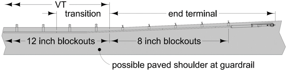
- This cell serves two purposes:
- To transition from variable tangent (VT) to BA-225.
- To set up a pavement edge transition (in areas with paved shoulders) from the 12 inch blockouts of the VT to the 8 inch blockouts of the BA-225.
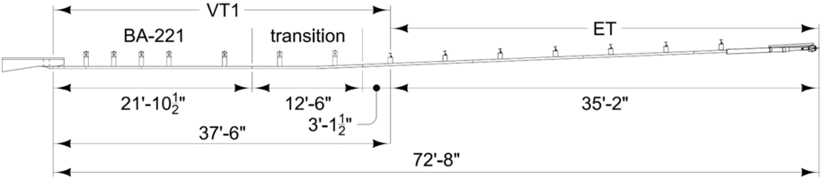
The transition is included in VT1, see Figure 2. The minimum length of VT1 is 37.5 feet. The minimum layout length for LS-635 is:
BA-221 with BA-225 = 21’-10½” + 12’-6” + 3’-1½” + 35’-2” = 72'-8″
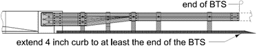
In order to limit the possibility of an impacting vehicle snagging on the concrete endpost, a 4 inch sloped curb is recommended underneath the guardrail in the area adjacent to the endpost. When used, the curb should start at the endpost and extend parallel to and outward from the endpost to at least the end of the BTS before transitioning to a no curb section, see Figure 3.
Back to top
MI-103
Deer Fence and Field Fence Construction
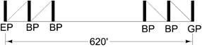
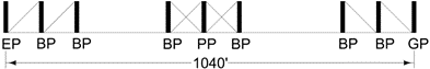
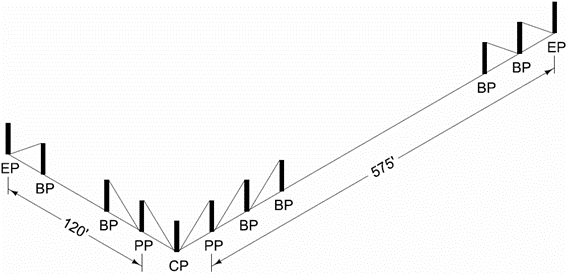
MI-103 shows several different brace panel layouts:
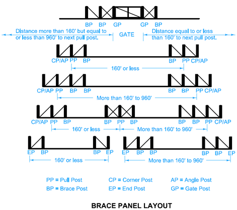
Distances of concern are between:
Two end posts,
Two pull posts,
A gate post and a pull post,
An end post and a gate post, and
An end post and a pull post.
When the distance is less than 160 feet, one brace post and panel is needed. When the distance exceeds 160 feet, an extra brace post and panel is needed. When the distance exceeds 960 feet, an intermediate pull post plus two additional brace posts and panels are needed.
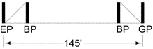
As an example, if the distance between an end post and a gate post is 145 feet, one brace post and panel is required with the end post, and one brace post and panel is required at the gate post.
If the distance is 620 feet, two brace posts and panels are required at the end post, and two brace posts and panels are required at the gate post.
If the distance is 1040 feet, an intermediate pull post with two brace posts and panels is needed.
As another example, if the distance from an end post to a pull post for a corner post is 120 feet and the distance to the next end post is 575 feet, the layout would look as follows:
Back to top
MI-104
Fence Construction at Channel Crossings, Flood Plains, and Minor Ground Depressions
MI-104 shows two types of channel crossings: Type A and Type B. Typically, Type A is used with smaller, low flowing streams. Type B is used with larger, higher flowing streams, or streams that have the potential to carry trash or other debris. Flood Plain Fence should be used in areas where flooding is expected. Extend the fence to the 5-year flood line.
Back to top
MI-210
PCC Driveways and Alleys
Designers should keep in mind that sidewalk panels adjacent to the driveway or alley may need to be reconstructed to transition from the existing sidewalk to the sidewalk through the driveway or alley. Include this in the sidewalk quantities.
Back to top
PMs
Pavement Markings
Refer to Design Manual 9D-1 for general information on pavement markings as well as guidance for turn lane markings.
Use 108-22 to tabulate pavement marking line types.
Use 108-29 to tabulate pavement marking symbols and legends.
The Pavement Marking Changes page explains recent changes to pavement markings.
Back to top
PR-120
Double Reinforced Pavement over Box Culverts
This standard includes double reinforced pavement. The intent is to reduce pavement issues related to potential differential settlement. This standard should not be used with new construction. Instead, it should be used where existing structures are being replaced. The most common uses for this standard include:
Replacing a box culvert using open excavation.
Replacing a bridge with a box culvert.
Typically, the backfill follows Standard Road Plan DR-111.
Back to top
PR-201
Runouts for Resurfacing
The use of surface runouts (Type ′R1′ and Type ′R2′) is generally limited to the case below:
1. No other milling is required on the project and the relative cost to mobilize a milling machine is excessive, and
2. There is evidence that using surface runouts in similar situations have yielded good results.
This case may appear on smaller resurfacing projects, such as MP projects or resurfacing at spot locations.
Back to top
PV-10
Rumble Strip Panel for Intersection Approach
When using this standard, which bid items to use depends on the situation.
Rumble Strip Panel Placed in Full Depth PCC Finish Patch.
Include all the following bid items:
- Patches, Full-Depth Finish, by Area. This covers the PCC quantity.
- Patches, Full-Depth Finish, by Count. This covers sawing or cutting and furnishing and installing dowels at patch edges.
- Rumble Strip Panel (In Full Depth Patch). This covers installing the rumble strips. The contractor has the option to form the rumble strips in plastic concrete, or to cut the rumble strips in.
Include the following bid items as needed:
- CD Joint Assembly.
- CT Joint.
Tabs needed: 102-6C and 112-7.
Rumble Strip Panel Cut into Existing PCC Pavement.
Include just the Rumble Strip Panel (PCC Surface) bid item.
Tab needed: 112-7.
Rumble Strip Panel Cut into HMA Pavement.
Include just the Rumble Strip Panel (HMA Surface) bid item.
Tab needed: 112-7.
Back to top
PV-12
Milled Shoulder Rumble Strips
Refer to Section 3C-5 for general information on milled rumble strips.
The default length (L) for shoulder rumble strips is 12 inches. On occasion, L may need to be less than 12 inches. The most common situation is bicycle accommodation. Another possible situation is rumble strips placed on a narrow shoulder. Contact Roadside Safety if planning to use a rumble strip length less than 12 inches.
Situations may arise (e.g. roads that carry horse and buggy traffic) such that rumble strips cannot be placed the standard 6 inches from the painted edge line. For those cases, Contact Roadside Safety for assistance with locating rumble strips.
Rumble strips should be discontinued 50 feet (measured from outside edge of railroad ties) from railroad crossings.
Use the 2548 bid item for fog seal for shoulder rumble strips. Refer to Section 2548 of the Standard Specifications for the dilution rate and application rate for calculating the fog seal quantity. This calculation is included in the calc file for the milled rumble strip tabulation.
Back to top
PV-13
Milled Centerline Rumble Strips
Refer to Design Manual 3C-5 for general information on milled rumble strips.
Per the 7/17/10 email from John Adam, centerline rumble strips will not be fog sealed. Do not include fog seal quantities for centerline rumble strips.
Back to top
PV-20
Raised Islands
Refer to the Project Design Criteria Worksheets within Section 1C-1 to determine which one of the three types of curb (4 inch sloped, 6 inch sloped, or 6 inch standard) should be used with a raised island.
Should a project call for a painted island, contact the Methods Section in the Design Bureau for assistance.
Back to top
PV-105
PCC Pavement Widening
Contractors prefer to dig trenches that are in 1 foot increments, so W should be in 1 foot increments.
Back to top
PV-106
PCC Railroad Approach Section
The approach pavement needs to match the grade of the tracks at the crossing. This means the pavement will need to be warped to transition to the proposed or existing cross slope at the EF joint. Depending on skew, much or all of this transition will occur between the ‘CD’ or ‘RD’ joint and the ‘EF’ joint. This can be handled using a smooth transition from the ‘CD’ or ‘RD’ joint to the ‘EF’ joint. Additional cross sections should be provided for this transition.
Designers also need to consider intakes that may exist between the ‘CD’ or ‘RD’ joint and the ‘EF’ joint. Pavement will need to be warped to accommodate those structures.
Contact the Pavement Design Engineer for pavement and subbase thickness.
Back to top
PV-204
PCC Railroad Approach Section
The approach pavement needs to match the grade of the tracks at the crossing. This means the pavement will need to be warped to transition to the cross slope of the proposed or existing pavement. Designers may want to include additional cross sections for this transition.
Designers also need to consider intakes that may exist adjacent to the approach section area. Pavement will need to be warped to accommodate those structures.
Back to top
PV-401
Parallel Deceleration Taper for 16’ Ramp (60 MPH Design Speed)
This standard is intended to be used where a parallel acceleration/deceleration lane is desired for improved operations and/or safety or due to other constraints (ROW, Environmental, etc.) on projects that involve interchanges, rest areas, or weigh scales.
The use of this standard is mandatory on new construction or reconstruction projects and it is recommended that they be incorporated into other projects (3R, 4R, etc.) if possible in the situations listed below:
- On any rural interstates, freeways, or expressways having three or more existing or 20 year design travel (future) lanes in one direction
- On Interstate 80 from Des Moines to Davenport
- On Interstate 380 from Coralville to Cedar Rapids
- On Interstate 35 from Des Moines to Ames
This standard may also be used on rural interstates, freeways, or expressways having two travel lanes in one direction on facilities where there is a desire to improve operations or safety, or there are other constraints (ROW, Environmental, etc.) preventing the use of the tapers provided in the Standard Road Plan PV series.
This standard may be used on urban interstates, freeways, or expressways having two or more existing or 20 year design travel (future) lanes in one direction, with consideration given to spacing to adjacent interchanges. If a traffic analysis indicates that an auxiliary lane is needed between subsequent interchanges, the details provided may be used by removing the tapered portion of the acceleration/deceleration lane and placing the details end to end thus creating the auxiliary lane.
This standard was designed using a design speed of 60 MPH, but is intended to be modified if a different design speed is desired. The length needed for the parallel portion of the acceleration/deceleration lane is determined by using a LOS analysis using Highway Capacity Manual concepts. Maintaining a LOS B for rural interstates is desirable; however, LOS C may be acceptable with FHWA approval. Maintaining a LOS C is desirable on urban interstates; however, LOS D may be acceptable with FHWA approval. This analysis requires breakdowns and volumes of traffic for the ramp and mainline, number of lanes on the ramp and mainline, and traffic speeds on the ramp and mainline. For projects being completed by IDOT staff, this analysis can be completed by the Geometrics Coordinator. For projects being completed by consultants, they will be responsible for completing this analysis. When this standard is modified for use on a project, it should be sent to the Geometrics Coordinator for review.
Contact the Geometrics Coordinator for additional information regarding use of this standard.
Back to top
PV-402
Parallel Acceleration Taper for 16’ Ramp (60 MPH Design Speed)
This standard is intended to be used where a parallel acceleration/deceleration lane is desired for improved operations and/or safety or due to other constraints (ROW, Environmental, etc.) on projects that involve interchanges, rest areas, or weigh scales.
The use of this standard is mandatory on new construction or reconstruction projects and it is recommended to be incorporated into other projects (3R, 4R, etc.) if possible in the situations listed below:
- On any rural interstates, freeways, or expressways having three or more existing or 20 year design travel (future) lanes in one direction.
- On Interstate 80 from Des Moines to Davenport.
- On Interstate 380 from Coralville to Cedar Rapids.
- On Interstate 35 from Des Moines to Ames.
This standard may also be used on rural interstates, freeways, or expressways having two travel lanes in one direction on facilities where there is a desire to improve operations or safety, or there are other constraints (ROW, Environmental, etc.) preventing the use of the tapers provided in the Standard Road Plan PV series.
This standard may be used on urban interstates, freeways, or expressways having two or more existing or 20 year design travel (future) lanes in one direction, with consideration given to spacing to adjacent interchanges. If a traffic analysis indicates that an auxiliary lane is needed between subsequent interchanges, the details provided may be used by removing the tapered portion of the acceleration/deceleration lane and placing the details end to end thus creating the auxiliary lane.
This standard was designed using a design speed of 60 MPH, but is intended to be modified if a different design speed is desired. The length needed for the parallel portion of the acceleration/deceleration lane is determined by using a LOS analysis using Highway Capacity Manual concepts. Maintaining a LOS B for rural interstates is desirable; however, LOS C may be acceptable with FHWA approval. Maintaining a LOS C is desirable on urban interstates; however, LOS D may be acceptable with FHWA approval. This analysis requires breakdowns and volumes of traffic for the ramp and mainline, number of lanes on the ramp and mainline, and traffic speeds on the ramp and mainline. For projects being completed by IDOT staff, this analysis can be completed by the Geometrics Coordinator. For projects being completed by consultants, they will be responsible for completing this analysis. When this standard is modified for use on a project, it should be sent to the Geometrics Coordinator for review.
Contact the Geometrics Coordinator for additional information regarding use of this standard.
Back to top
PV-403
Parallel Deceleration Taper for 18’ Exit Loop (60 MPH Design Speed)
This standard is intended to be used where a parallel acceleration/deceleration lane is desired for improved operations and/or safety or due to other constraints (ROW, Environmental, etc.) on projects that involve interchanges, rest areas, or weigh scales.
The use of this standard is mandatory on new construction or reconstruction projects and it is recommended to be incorporated into other projects (3R, 4R, etc.) if possible in the situations listed below:
- On any rural interstates, freeways, or expressways having three or more existing or 20 year design travel (future) lanes in one direction.
- On Interstate 80 from Des Moines to Davenport.
- On Interstate 380 from Coralville to Cedar Rapids.
- On Interstate 35 from Des Moines to Ames.
This standard may also be used on rural interstates, freeways, or expressways having two travel lanes in one direction on facilities where there is a desire to improve operations or safety, or there are other constraints (ROW, Environmental, etc.) preventing the use of the tapers provided in the Standard Road Plan PV series.
This standard may be used on urban interstates, freeways, or expressways having two or more existing or 20 year design travel (future) lanes in one direction, with consideration given to spacing to adjacent interchanges. If a traffic analysis indicates that an auxiliary lane is needed between subsequent interchanges, the details provided may be used by removing the tapered portion of the acceleration/deceleration lane and placing the details end to end thus creating the auxiliary lane.
This standard was designed using a design speed of 60 MPH, but is intended to be modified if a different design speed is desired. The length needed for the parallel portion of the acceleration/deceleration lane is determined by using a LOS analysis using Highway Capacity Manual concepts. Maintaining a LOS B for rural interstates is desirable; however, LOS C may be acceptable with FHWA approval. Maintaining a LOS C is desirable on urban interstates; however, LOS D may be acceptable with FHWA approval. This analysis requires breakdowns and volumes of traffic for the ramp and mainline, number of lanes on the ramp and mainline, and traffic speeds on the ramp and mainline. For projects being completed by IDOT staff, this analysis can be completed by the Geometrics Coordinator. For projects being completed by consultants, they will be responsible for completing this analysis. When this standard is modified for use on a project, it should be sent to the Geometrics Coordinator for review.
Contact the Geometrics Coordinator for additional information regarding use of this standard.
Back to top
PV-404
Parallel Deceleration Taper for 24’ Ramp (60 MPH Design Speed)
This standard is intended to be used where a parallel acceleration/deceleration lane is desired for improved operations and/or safety or due to other constraints (ROW, Environmental, etc.) on projects that involve interchanges, rest areas, or weigh scales.
The use of these standard is mandatory on new construction or reconstruction projects and it is recommended that they be incorporated into other projects (3R, 4R, etc.) if possible in the situations listed below:
- On any rural interstates, freeways, or expressways having three or more existing or 20 year design travel (future) lanes in one direction
- On Interstate 80 from Des Moines to Davenport
- On Interstate 380 from Coralville to Cedar Rapids
- On Interstate 35 from Des Moines to Ames
This standard may also be used on rural interstates, freeways, or expressways having two travel lanes in one direction on facilities where there is a desire to improve operations or safety, or there are other constraints (ROW, Environmental, etc.) preventing the use of the tapers provided in the Standard Road Plan PV series.
This standard may be used on urban interstates, freeways, or expressways having two or more existing or 20 year design travel (future) lanes in one direction with, consideration given to spacing to adjacent interchanges. If a traffic analysis indicates that an auxiliary lane is needed between subsequent interchanges, the details provided may be used by removing the tapered portion of the acceleration/deceleration lane and placing the details end to end thus creating the auxiliary lane.
This standard was designed using a design speed of 60 MPH, but is intended to be modified if a different design speed is desired. The length needed for the parallel portion of the acceleration/deceleration lane is determined by using a LOS analysis using Highway Capacity Manual concepts. Maintaining a LOS B for rural interstates is desirable; however, LOS C may be acceptable with FHWA approval. Maintaining a LOS C is desirable on urban interstates; however, LOS D may be acceptable with FHWA approval. This analysis requires breakdowns and volumes of traffic for the ramp and mainline, number of lanes on the ramp and mainline, and traffic speeds on the ramp and mainline. For projects being completed by IDOT staff, this analysis can be completed by the Geometrics Coordinator. For projects being completed by consultants, they will be responsible for completing this analysis. When this standard is modified for use on a project, it should be sent to the Geometrics Coordinator for review.
Contact the Geometrics Coordinator for additional information regarding use of this standard.
Back to top
PV-405
Parallel Acceleration Taper for 24’ Ramp (60 MPH Design Speed)
This standard is intended to be used where a parallel acceleration/deceleration lane is desired for improved operations and/or safety or due to other constraints (ROW, Environmental, etc.) on projects that involve interchanges, rest areas, or weigh scales.
The use of this standard is mandatory on new construction or reconstruction projects and it is recommended to be incorporated into other projects (3R, 4R, etc.) if possible in the situations listed below:
- On any rural interstates, freeways, or expressways having three or more existing or 20 year design travel (future) lanes in one direction.
- On Interstate 80 from Des Moines to Davenport.
- On Interstate 380 from Coralville to Cedar Rapids.
- On Interstate 35 from Des Moines to Ames.
This standard may also be used on rural interstate, freeways, or expressways having two travel lanes in one direction on facilities where there is a desire to improve operations or safety, or there are other constraints (ROW, Environmental, etc.) preventing the use of the tapers provided in the Standard Road Plan PV series.
This standard may be used on urban interstates, freeways, or expressways having two or more existing or 20 year design travel (future) lanes in one direction, with consideration given to spacing to adjacent interchanges. If a traffic analysis indicates that an auxiliary lane is needed between subsequent interchanges, the details provided may be used by removing the tapered portion of the acceleration/deceleration lane and placing the details end to end thus creating the auxiliary lane.
This standard was designed using a design speed of 60 MPH, but is intended to be modified if a different design speed is desired. The length needed for the parallel portion of the acceleration/deceleration lane is determined by using a LOS analysis using Highway Capacity Manual concepts. Maintaining a LOS B for rural interstates is desirable; however, LOS C may be acceptable with FHWA approval. Maintaining a LOS C is desirable on urban interstates; however, LOS D may be acceptable with FHWA approval. This analysis requires breakdowns and volumes of traffic for the ramp and mainline, number of lanes on the ramp and mainline, and traffic speeds on the ramp and mainline. For projects being completed by IDOT staff, this analysis can be completed by the Geometrics Coordinator. For projects being completed by consultants, they will be responsible for completing this analysis. When this standard is modified for use on a project, it should be sent to the Geometrics Coordinator for review.
Contact the Geometrics Coordinator for additional information regarding use of this standard.
Back to top
PV-418
One-Lane Detour Connection
Refer to TC-253 for pavement markings and traffic control.
Refer to Detour Typical for related information.
Refer to Section 9C-6 for additional information.
Back to top
PV-428
Two-Lane Detour Connection
Refer to TC-253 for pavement markings and traffic control.
Refer to Detour Typical for related information.
Refer to Section 9C-6 for additional information.
Back to top
SI-175
Chevrons
To calculate S, the spacing of chevrons, use Table 2C-6 on page 113 of the 2009 MUTCD.
Follow the link to the 2009 MUTCD (http://mutcd.fhwa.dot.gov/).
Back to top
SW-538
Intake for Bridge End Drain
Refer to Section 4C-2 for information regarding hydraulic evaluation and determining the location of intake bridge end drains. Refer to Section 7D-1 for information pertaining to determining reinforced bridge approach section dimensions.
|
| Circle note 2 instructs the contractor to continue the 4 inch sloped curb 5 feet beyond the centerline of the intake, then transition to a no curb section. Verify this transition does not occur within the BTS or the end terminal for barrier rail (refer to BA standards). If it does, relocate the curb drop transition and note the location in the plans with either a plan note or a modified SW-538. |
|---|
Back to top
SW-539
Intake for Bridge End Drain
Refer to Section 4C-2 for information regarding hydraulic evaluation and determining the location of intake bridge end drains. Refer to Section 7D-1 for information pertaining to determining reinforced bridge approach section dimensions.
|
| Circle note 2 instructs the contractor to continue the 4 inch sloped curb 5 feet beyond the centerline of the intake, then transition to a no curb section. Verify this transition does not occur within the BTS or the end terminal for barrier rail (refer to BA standards). If it does, relocate the curb drop transition and note the location in the plans with either a plan note or a modified SW-539. |
|---|
Back to top
SW-541
Open-throat Curb Intake under Pavement
This standard places the well under the pavement. This can result in the casting being placed in a traveled lane. Though not unacceptable, it is undesirable since access to the well is now in a traveled lane. Intakes that place the well outside of the pavement should be considered first. Situations that might involve using SW-541 include areas where:
right-of-way restrictions or the location of existing utilities don’t allow for placement of the well outside of the pavement.
existing storm sewer is located under the pavement.
intakes fall within a barrier rail installation.
Contact Roadside Safety for situations that involve barrier rail conflicting with an SW-541 installation.
Back to top
SW-542
Open-throat Curb Intake under Pavement
This standard is used with SW-541. SW-541 places the well under the pavement. This can result in the casting being placed in a traveled lane. Though not unacceptable, it is undesirable since access to the well is now in a traveled lane. Intakes that place the well outside of the pavement should be considered first. Situations that might involve using SW-541 include areas where:
right-of-way restrictions or the location of existing utilities don’t allow for placement of the well outside of the pavement.
existing storm sewer is located under the pavement.
intakes fall within a barrier rail installation.
Contact Roadside Safety for situations that involve barrier rail conflicting with an SW-542 installation.
Back to top
SW-602
Castings for Storm Sewer Manholes
Normally DOT projects will specify Type F castings which are used with PCC surfaces, including castings in concrete boxouts. Type E (Fixed) is generally used with non-paved or flexible surfaces, including HMA, seal coat, gravel and brick.
Back to top
TC-218
Lane Closure with Pilot Car and Flagger Operated Signals
Include information in the Temporary Traffic Signals estimate reference note to inform contractors how many sets of signals are included in the bid item. Typically, 1 set includes 2 signals. Signals are not bid for sideroads and private entrances. Instead, designers will need to add bid items for flaggers for sideroads. Flaggers are normally not bid for private entrances. High volume private entrances may need a flagger. Discuss this with the District.
Back to top
TC-451
Temporary Road Closure on Divided Highway
The use and contact of the law enforcement vehicle and officer is a function of the RCE Office. Sometimes this vehicle is paid by Extra Enforcement funds and other times this is an effort of the enforcement community using normal shift officers. No action is needed by designers in regards to the law enforcement vehicle.
Back to top
TC-454
Temporary Detour Using Ramps on Divided Highway
The use and contact of the law enforcement vehicle and officer is a function of the RCE Office. Sometimes this vehicle is paid by Extra Enforcement funds and other times this is an effort of the enforcement community using normal shift officers. No action is needed by designers in regards to the law enforcement vehicle.
Back to top