Content Information
On this page...
100-01D
Project Description
This tabulation is not required. Designers may include it in the plans if they feel the project description on the A.01 Title Sheet is not comprehensive enough.
Back to top
100-10
Floating Silt Curtains
Refer to Section 10C-1 for information regarding floating silt curtains. Include the Developmental Specifications for Floating Silt Curtain. Best Management Practices (BMPs) (erosion and sediment control measures) are required throughout the construction site and immediately uphill of the curtains to minimize sediment migration to the curtains.
Back to top
100-13
Silt Ditches
Refer to Standard Road Plan EW-403 for details of silt ditches. For volume calculation purposes, the following assumptions have been made:
- Depth is 2 feet.
- Width is 10 feet.
- Side slopes of ditches are 1:1.
Back to top
100-14
Silt Basins
Refer to 10C-1 for bid quantity items and multipliers.
Refer to Section 10C-2 for more information regarding filling out this tab.

| The calc file assumes if you type in .1 for Average % Slope, you mean 10%. If you type in .01, the calc file assumes you mean 1%. To enter a slope less than 1%, type in a 0.X, i.e. type a 0 before the decimal point. For example, type in 0.6 for a slope of 0.6%, 0.8 for a slope of 0.8%, etc. |
|---|
Back to top
100-15
Silt Dikes
Refer to Standard Road Plan EW-403 for details of silt dikes. For volume calculation purposes, the following assumptions have been made:
- Depth of water on the shallow side is 6 inches.
- Depth of water on the deep side is 18 inches.
- Width is 10 feet.
- Sides of ditches are vertical.
Back to top
100-17
Silt Fences
Refer to 10C-1 for bid quantity items and multipliers.
Back to top
100-18
Silt Fences for Ditch Checks
Refer to 10C-1 for bid quantity items and multipliers.
Refer to Section 10C-2 for more information regarding filling out this tab.
|
| The calc file assumes if you type in .1 for Average % Slope, you mean 10%. If you type in .01, the calc file assumes you mean 1%. To enter a slope less than 1%, type in a 0.X, i.e. type a 0 before the decimal point. For example, type in 0.6 for a slope of 0.6%, 0.8 for a slope of 0.8%, etc. |
|---|
Back to top
100-19
Perimeter and Slope Sediment Control Device
Refer to Design Manual 10C-1, Standard Road Plan EC-204, and Sections 2602 and 4169 in the Specifications for additional information.
The tabulation is set up to match the diameters provided by the bid item descriptions for these devices. These bid items were created using the manufactured sizes for Wood Excelsior Logs and Straw Wattles. Since the bid items are titled Perimeter and Slope Sediment Control Devices, the Contractor has the option of using either of those two products or Filter Socks.
Since these devices are generally used in conjunction with silt fence, tab the diameter as determined in Design Manual 10C-1. Do not tabulate the 6 inch or 9 inch size unless recommended by Roadside Development, Office of Construction, District Personnel, or RCE.
Please note, the Removal Bid Item (if applicable) for these devices is to be detailed in the plans. Since these devices are usually left in place to degrade, the Removal item was left off the tabulation.
Back to top
100-22
Rolled Erosion Control
For guidance on Turf Reinforcement Mats, refer to the designer information for Standard Road Plan EC-104 in Section 1E-6. Contact the Agronomist with additional questions regarding choosing which type of TRM to choose.
Back to top
100-25
HMA Pavement
For a list of available unit weights for use in the calculations note, as well as where to use them, refer to 1B-4.
Back to top
100-26
Incidental Items
Tabulate all items which the designer elected to make incidental through plan notes. Items that are normally defined as incidental in the specifications or Standard Road Plans should not be listed.
Back to top
100-27
Proposed Posted Speed Limits
The purpose of this tabulation is to relate the proposed posted speed limit of a section of roadway to the pavement smoothness requirements of Sections 2316 and 2317 of the Standard Specifications. Those sections also explain where pavement smoothness is evaluated. Designers should be familiar with those sections when filling out Tabulation 100-27.
|
| Be sure to include all pavement surfaces that require pavement surface smoothness evaluation in Tabulation 100-27; otherwise, contractors may not realize pavement smoothness is required. |
|---|
Back to top
100-28
Longitudinal Grooving
Include this tab when bridge approaches are placed (or replaced) along with a new or reconstructed bridge.
Back to top
100-32
Rock Check Dam
Refer to Section 10C-1 for guidance on bid item quantities.
Refer to Section 10C-2 for more information regarding filling out this tab.
|
| The calc file assumes if you type in .1 for Average % Slope, you mean 10%. If you type in .01, the calc file assumes you mean 1%. To enter a slope less than 1%, type in a 0.X, i.e. type a 0 before the decimal point. For example, type in 0.6 for a slope of 0.6%, 0.8 for a slope of 0.8%, etc. |
|---|
Back to top
100-33
Temporary Sediment Control Basin
Refer to Section 10C-1 for guidance on bid item quantities.
Refer to Section 10C-2 for more information regarding filling out this tab.
|
| The calc file assumes if you type in .1 for Average % Slope, you mean 10%. If you type in .01, the calc file assumes you mean 1%. To enter a slope less than 1%, type in a 0.X, i.e. type a 0 before the decimal point. For example, type in 0.6 for a slope of 0.6%, 0.8 for a slope of 0.8%, etc. |
|---|
Back to top
100-34
Stormwater Drainage Basin
Refer to Section 10C-2 for more information regarding filling out this tab.
Back to top
102-05
Existing Pavement
The layout of this tab changed dramatically for the October 2011 revision. The tab columns now match the Pavement Management Information System (PMIS) “Test Section by Milepost” booklet. Several methods are available to retrieve the information to fill out the tab, one of which is discussed below.
To retrieve pavement history information, view the .pdf file of the published “Test Section by Milepost” booklet (available at https://iadot.sharepoint.com/sites/XDIV/TAM/PMSC/SitePages/Home.aspx). Find the information needed and either copy or type it into the 102-05 tab. Follow the same steps to incorporate the abbreviations key. The abbreviations can be found at the beginning of the .pdf booklet (usually around page 3).
To obtain information for the Reinforcement (Type) column, one option is to locate the project in ERMS and view the pavement details or standards noted within the plans.
Back to top
102-05A
Existing HMA Pavement for Recycling
This tab provides information to assess the value of scarified material for other uses. It should be included whenever scarification exceeds 500 tons or 4500 square yards. When these scarification values are exceeded, notify the District Materials Engineer so they can research pavement histories and develop values to be placed in the tabulation.
Column Descriptions
% of -4 that is Type 2
The percentage of Type 2 frictional aggregate within the fine portion passing the #4 sieve.
% of +4 that is Type 2
The percentage of Type 2 frictional aggregate within the coarse portion retained on the #4 sieve.
% of +4 that is Type 3
The percentage of Type 3 frictional aggregate within the coarse portion retained on the #4 sieve.
% of +4 that is Type 4
The percentage of Type 4 frictional aggregate within the coarse portion retained on the #4 sieve.
Back to top
102-10
Partial Depth PCC Finish Patches
Although Overdepth Patches is a bid item, they are not tabulated since the need for overdepth patches is usually determined in the field when a partial depth patch is being done. If the need for an overdepth patch has been determined beforehand (e.g., during a field review), designers can tab them in the Remarks column.
Partial Depth PCC Joint and Crack Repair Patches are bid by the linear foot because Article 2530.04, B, 1 of the Standard Specifications notes a 12 inch width of repair is assumed.
Back to top
103-10
Topsoil Tab
This tab will appear in the CS Sheets. It is used in conjunction with the Earthwork sheets, but is specific to projects with varying Topsoil Stripping Thicknesses. Use this tab only when stripping or placement thicknesses will vary within the project. Otherwise, note the thickness in the T-Sheets.
Back to top
104-03
Drainage Structure by Road Contractor
When filling in the Length New Const. column, enter the pipe length without the aprons.
When filling in the Dimensions columns, the Total and Extensions columns include pipe plus apron.
Equivalent diameters for arch and elliptical pipes can be found on DR-202.
The Camber column is set up to autofill as values are typed into the Design Cover column. Camber values come from the Allowable Camber Tables on DR-102. Normal Camber is assumed. Designers can type in values as well, e.g. should the Soils Design Section require a different camber than what is DR-102, or should fill height exceed 35 feet.
When calculating floodable backfill, keep in mind the depth varies as a result of the crown at the top and the pitch of the pipe.
Back to top
104-04
Drainage Structures by Culvert Contractor
Normally, culverts are let a year in advance of the paving and backfilled according to the Compaction Adjacent to Structures specifications. The Floodable Backfill columns on this tab normally will not contain values. Occasionally, the pavement above the culvert will be constructed in the same year as the culvert. In these cases, flooded backfill is often used to prevent pavement issues caused by settlement of this material.
The Type column under Excavation has a pull down menu with the most common types of excavation associated with culvert installation. Typically, Type and Quantity are determined by the Office of Bridges and Structures and included in their plans.
The Type column under Revetment has two options: Class D or Class E (see Article 4130.02 of the Standard Specifications). Which type to choose will depend on the water velocity at the culvert outlet. Higher velocities will require Class E, which is processed to remove smaller material.
Compaction with Excavated Material
Culverts are backfilled according to the Embankments Adjacent to Culverts and Structures specifications (see Section 2107), and the Placing Backfill Materials and Embankments Adjacent to Bridges, Culverts, or Structures specifications (see Section 2402 of the Standard Specifications). Article 2107.04, B, 4 explains how to calculate quantities for compaction adjacent to bridges, culverts, or structures. The specifications assume contractors will need to use mechanical or pneumatic tampers out a distance of 4 feet from the structure. The remainder of the backfill can be compacted using a roller. Compaction by tampers is more labor intensive, so it is costlier. That is why it is bid separately from the remainder of the compaction.
The Soils Design Section will determine the limits of compaction with moisture control or compaction with moisture and density control.
Compaction with Flooded Backfill
Backfill consists of a combination of flooded backfill and suitable material, see DR-111. Flooded backfill is used to the top of culvert for culvert heights of 5 feet or less, with the remaining backfill consisting of suitable backfill material. For culvert heights of more than 5 feet, flooded backfill is used up to a height of 5 feet, with the remaining backfill consisting of suitable backfill. The contractor has the option to use floodable backfill in place of the suitable material. For calculating quantities, assume the contractor will use suitable backfill material. Also assume the top of the floodable backfill is level. The depth of floodable backfill will vary as a result of the pitch of the pipe.
Compaction with moisture control is required for the excavated material placed. The bid item for Compacting Backfill Adjacent to Bridges, Structures, Culverts or Structures covers the expense for the extra effort required to do the compaction, not the material. The material used is simply the excavated material used for backfill and is accounted for in that quantity.
The quantity of flooded backfill is equal to floodable backfill plus porous backfill. For the porous backfill, assume a cross section equal to an 8 inch square minus a 4 inch diameter circle, which is approximately 0.04 yd2.
Back to top
104-05B
Storm Sewer
Connected pipe joints are used for outlet pipes as shown on DR-121. Include SW-211 in the plans when pipe joints are to be wrapped. Even though DR-121 includes a detail for pipe joint wrapping, Article 2503.03, D, 2 of the Standard Specifications calls out SW-211 for consistency with SUDAS. The pipe wrapping detail is the same on both standards.
Equivalent diameters for arch and elliptical pipes can be found on DR-202.
Back to top
104-05C
List of Subdrain Work
Contact the Soils Design Engineer early in the process of filling in Tab 104-5C. Depending on the project, the number of notes and remarks required to fill in the tab correctly can make the tab very complex.
Back to top
104-06
Wick Drain or Sand Drain Fields
Wick drains, sand drains, and horizontal strip drains serve a similar purpose as subdrains – to remove subsurface water. However, wick drains, sand drains, and horizontal strip drains use aggregate to transport water rather than a pipe. A sand drain field is simply a group of sand drains used to drain an area.
Refer to Section 2112 of the Standard Specifications for more information regarding wick drains. Like wick drains, sand drains and horizontal strip drains are a 2112 bid item.
Contact Soils Design Section in the Office of Design for assistance with filling out Tab 104-6.
Back to top
104-09
Longitudinal Subdrain Shoulder and Backslope
Contact the Soils Design Engineer early in the process of filling in Tab 104-9. Depending on the project, the number of notes and remarks required to fill in the tab correctly can make the tab very complex.
For bridge berms, a trench depth of 24 inches below subgrade surface is assumed. Porous backfill makes up 18 inches of the backfill, with the remaining 6 inches being Class ″A″ crushed stone. The formulas for both the Porous Backfill and the Class ″A″ Crushed Stone columns account for this.
Back to top
104-12
Subdrain and Grading at Side Piers
A trench depth of 24 inches is assumed. Porous backfill makes up 18 inches of the backfill, with the remaining 6 inches being Class ″A″ crushed stone. The formulas for both the Porous Backfill and the Class ″A″ Crushed Stone columns account for this.
Back to top
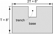
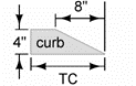
104-14
Linear Trench Drain
To simplify calculations, the cross sectional area is broken into two areas: the base area and the curb area. These are calculated in columns K and L. Volume is calculated in column M by multiplying the total cross sectional area (columns K + L) by the length of the installation.
Base Area
To calculate the base area, A 6 inch by 8 inch trench is assumed.
Installation without Curb
The top is pitched to match adjacent pavement. To simplify calculations, the top is assumed flat. The base area (shaded region below) is calculated as:
Installation with Curb
The top portion adjacent to the pavement is pitched to match the adjacent pavement. To simplify calculations, it is assumed flat. The base area (shaded region below) is calculated as:
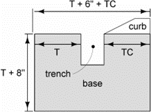
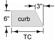
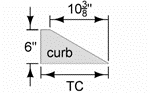
Curb Area
PV-102 provides details for curbs. Although the details show radii to transition breakovers, to simplify calculations these are ignored for calculating cross sectional areas. The resulting areas are trapezoids.
6 Inch Standard Curb
The area is calculated as shown below.
6 Inch Sloped Curb
The area is calculated as shown below.
4 Inch Sloped Curb
The area is calculated as shown below.
Filling in Tab 104-14
The Direction of Travel, Side, Curb, and Curb Type columns contain pull down menus. The Length, Base Cross Section Area, Curb Cross Section Area, and PCC columns autofill as data is added into the other columns.
If the CURB column is not populated, the CURB TYPE and PCC columns will not populate and the BASE CROSS SECTION AREA column may not display correctly. Designers must choose either Yes or No for CURB.

If Yes is chosen for the CURB column, the CURB CROSS SECTION AREA column will display a negative value until a value is input in the TC column:


|
| The CURB CROSS SECTION AREA column depends on the CURB TYPE column. The CURB TYPE column I has 3 curb options in the pull down menu: 6 inch standard, 6 inch sloped, and 4 inch sloped. If a curb type other than these is entered, the CURB CROSS SECTION column will default to a 6 inch standard curb for calculations. If using a curb type other than those in the drop down menu, the equation in the CURB CROSS SECTION column in will need to be changed to accommodate the curb cross section. |
|---|
If No is chosen for the CURB column, the CURB TYPE column is left blank. The BASE CROSS SECTION and PCC columns will start to populate. The BASE CROSS SECTION and PCC columns will calculate once the T column is populated:


Base Cross Section Area and Curb Cross Section Area columns do not appear when Tab 104-14 is printed.
Back to top
105-04
Standard Road Plans
This tab will now come with TC-1 Work Not Affecting Traffic (Two-Lane or Multi-Lane) already appearing in the list of Standard Road Plans.
The Date column is blank on purpose. After selecting which revision to choose or update standards from, a message box will appear to alert the user that the listed TC-1 is out of date and ask if they would like the date updated to the correct release date (not necessarily the same date as the revision box selected). If the user selects Yes, the program will open to the List of Standard Road Plans window and TC-1 will be checked. If the user selects No, the window will open but TC-1 will not be checked. Since TC-1 is REQUIRED FOR ALL DEPARTMENT PROJECTS, users should select Yes at this message box. From there, select any additional SRPs as usual. After clicking OK in the List window, TC-1 will appear with the correct date.
This change provides an additional safeguard for us to comply with an Iowa OSHA ruling that all Department projects are required to include this SRP.
Back to top
106-05
Areas for Pavement or Base Widening
For a list of available unit weights for use in the calculations note, as well as where to use them, refer to 1B-4.
When HMA is bid by weight, include the item for Asphalt Binder. When HMA is bid by area, the item for Asphalt Binder is not included. See Article 2213.04, E of the Standard Specifications.
Back to top
107-28
Tabulation of Template Quantities and Adjustments
This tabulation replaces 107-29 and 107-30 whenever a DOT borrow is not provided. When this tabulation is used, overhaul is not calculated and balances are not shown on the plan and profile sheets. Subtotals need to be added for each alignment and stage. Each sheet should have a minimum of one subtotal. A summary and grand total should be at the bottom of the last sheet. The top of each column will have a sequential number, and include a formula if there is any calculation required to obtain that result. An example of the desired result is shown in Section 1F-20.
Refer to Section 5B-3 for more information regarding contractor furnished borrow.
Back to top
108-08A
Steel Beam Guardrail at Concrete Barrier or Bridge Rail End Section
Refer to 8B-10 for sample tabulations.
Back to top
108-08C
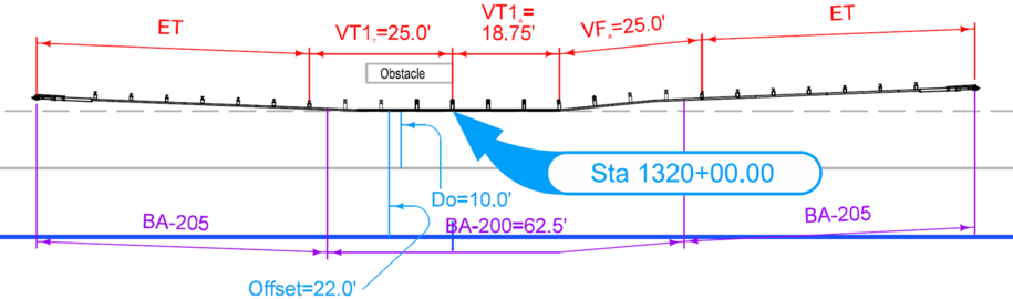
Steel Beam Guardrail for Side Obstacle (Two-way Protection)
Refer to 8B-10 for sample tabulations.
The total of VT2A plus VFA plus VT1A plus VT1T minus 6.25 must be a multiple of 12.5. That’s because each BA-205 has 3.125 feet of W-beam that needs to be subtracted out to determine total BA-200.
For Example 4 in Section 8B-10, VFA is 25 feet, VT1T is 25 feet, and VT1A is 18.75 feet. VT1A it is at least 12.5 feet and is a multiple of 6.25 feet. The total VT ends up being 25 + 18.75 + 25 = 68.75 feet. Subtracting 6.25 feet from 68.75 feet results in length of BA-200 = 62.5 feet. That is a multiple of 12.5.
Back to top
108-18
Concrete Barrier at Median Locations
A number of BA Standard Road Plans state that “Expansion Joints are necessary only where specifically required by project plans.” To clarify, expansion joints are required in the following situations:
- If there is an expansion joint in the pavement below the barrier, such as in a bridge approach section, or
- If the barrier is butting into a separate structure, such as a bridge pier, sign truss footing, bridge rail, etc.
This tabulation is to be used for median installations. This could also include situations where a single median barrier splits into two half-sections in order to protect median bridge piers.
Back to top
108-18B
Concrete Barrier at Side Locations
A number of BA100s Standard Road Plans state that “Expansion Joints are necessary only where specifically required by project plans.” To clarify, expansion joints are required in the following situations:
- If there is an expansion joint in the pavement below the barrier, such as in a bridge approach section, or
- If the barrier is butting into a separate structure, such as a bridge pier, sign truss footing, bridge rail, etc.
Back to top
108-20
Concrete Barrier with MSE Wall
Refer to instructions outlined in 8208.
Back to top
108-22
Pavement Marking Line Types
This section provides guidance for filling out the Pavement Marking Line Types tabulation for various situations encountered during design. Refer to the PM Series for layout guidance, specifically PM-110 for line type information.
Line Types
Under the ‘Length by Line Type (Unfactored)’ heading are several columns available for different line types. The first six columns are pre-selected with the most common line types. These should be left visible and in their current order to provide continuity between appearances of this tab in different projects. Click on an empty column header to bring up a pull-down menu to select other pavement marking types as required by the project. In the instance that a project requires more than nine additional slots and any of the first six are not used, they may be replaced as needed. If a project needs more than fifteen different line types: 1) rename filled orange and blue worksheet tabs 108-22A leaving the tab header as 108-22; 2) add an additional page of this tab (notice the box for 108-22 is now unchecked) and name the new orange and blue worksheet tabs 108-22B, again leaving the actual tab header alone; 3) replace the pre-selected line types with those needed; and 4) set any remaining pre-selected types to blank.
After selecting a line type, the factors line and the line type description will update accordingly.
Marking Types
Below are the available marking types and when to use each.
|
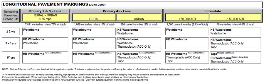
| NOTE: For new or resurfaced pavements, initial pavement markings should be nondurable surface applied waterborne paint (use Waterborne/Solvent Paint bid item). More durable pavement markings, and grooving, should not be used until the construction season following the construction of the new pavement. Table 1, below, is to be used to determine pavement marking types for existing pavements. |
|---|
- Waterborne/Solvent Paint – This may be used as longitudinal markings in construction zones using temporary traffic control where the marking is temporary and needs to be removed after construction. For permanent application see Table 1.
- Highbuild Waterborne Paint – See Table 1.
- Durable Paint – A catchall for remaining paints. Generally, either Waterborne/Solvent or Highbuild Waterborne are preferred.
- Permanent Regular Tape – Also known as foil tape. Do not use without consent from the State Traffic Engineer.
- Permanent Preformed Polymer Tape – Do not use without consent from the State Traffic Engineer.
- Permanent Profiled Tape – Preferred type of tape. Use according to Table 1.
- Permanent Intersection Tape – Intended for crosswalks, gore lines, and symbols at intersections where markings are subjected to high shear from turning traffic.
- Groove Cuts for Pavement Markings – Intended for use when final pavement markings are placed. Use in conjunction with the requirements set forth in the note above. The request for grooving will come from the District.
- Wet Retroreflective Removable Tape – Intended for use as diagonal markings in construction zones using temporary traffic control where the marking is temporary and needs to be removed after construction. See Article 2527.03, I, 2, of the Standard Specifications.
- Nonreflective, Preformed Removable Tape – Intended to temporarily cover up areas that have existing markings that will be re-used in the future (for example, covering existing markings during construction staging).
- Removal of Paint or Permanent Tape – To identify any markings to be removed.
- Removal of Removable Tape – To identify any markings to be removed where the removal portion is incidental to the initial placement (for example, removable tape). Mostly used as a sequencing or staging place holder.
Table 1: Longitudinal Pavement Marking Matrix
Tabulation Entry Guidelines
The proper tabulation of pavement marking line types is critical to provide the contractor a definitive location of each marking.
Pavement marking line types should be tabulated using the following guidelines:
- Tabulate markings based on staging.
- Provide station to station limits consistent with marking location.
- Each designation of ‘Standard Roadway Conditions’ should be tabulated in an entry which is separate from any ‘Special Conditions’, as described below.
- Note the presence of interchanges and intersections will result in edge line quantities that differ from the edge line descriptions below and must be tabulated separately with appropriate station to station limits.
- Limit one ‘Special Condition’ per entry, unless an identical station to station range exists.
- The ‘Standard Roadway Conditions’ described below do not apply to the tabulation of markings for TC Series Standard Road Plans.
Standard Roadway Conditions
The Length of Marking items below were initially created with the assumption that the Station to Station values were manually entered and used to create the Length values. If values are created with the Design and Computation Manager - Compute tool (or any similar program) that generates the length values in a report, ignore the suggested lengths below and use those numbers instead.
Two-Lane Roadways
Use the following selections to tab this scenario:
White Edge Lines
Direction of Travel → BOTH
Side → R
Line Type → ELW4
Length of Marking → Twice the amount shown in Length column
Centerline
Direction of Travel → Either of the actual directions
Side → L
Line Type → BCY4 or DCY4 or NPY4
Length of Marking → Amount shown in Length column
Four-Lane Undivided Roadways
Use the following selections to tab this scenario:
White Edge Lines
Direction of Travel → BOTH
Side → R
Line Type → ELW4
Length of Marking → Twice the amount shown in Length column
Lane Lines
Direction of Travel → BOTH
Side → C
Line Type → BLW4
Length of Marking → Twice the amount shown in Length column
Centerline
Direction of Travel → Either of the actual directions
Side → L
Line Type → DCY4 or NPY4
Length of Marking → Amount shown in Length column
Four-Lane Divided Roadways
Use the following selections to tab this scenario:
White Edge Lines
Direction of Travel → BOTH
Side → R
Line Type → ELW4
Length of Marking → Twice the amount shown in Length column
Lane Lines
Direction of Travel → BOTH
Side → C
Line Type → BLW4
Length of Marking → Twice the amount shown in Length column
Yellow Edge Lines
Direction of Travel → BOTH
Side → L
Line Type → ELY4
Length of Marking → Twice the amount shown in Length column
More than Four-Lane Divided Roadways
Use the following selections to tab this scenario:
White Edge Lines
Direction of Travel → BOTH
Side → R
Line Type → ELW4
Length of Marking → Twice the amount shown in Length column
Lane Lines
Direction of Travel → BOTH
Side → C
Line Type → BLW4
Length of Marking → Four times the amount shown in Length column for Six-Lanes or Six times the amount shown for Eight-Lanes
Yellow Edge Lines
Direction of Travel → BOTH
Side → L
Line Type → ELY4
Length of Marking → Twice the amount shown in Length column
Four Lane Interstates
Use the following selections to tab this scenario:
- White Edge Lines
- Direction of Travel → BOTH
- Side → R
- Line Type → ELW6
- Length of Marking → Twice the amount shown in Length column
- Lane Lines
- Direction of Travel → BOTH
- Side → C
- Line Type → BLC6
- Length of Marking → Twice the amount shown in Length column
- Yellow Edge Lines
- Direction of Travel → BOTH
- Side → L
- Line Type → ELY6
- Length of Marking → Twice the amount shown in Length column
Multi-lane Interstates
Use the following selections to tab this scenario:
- White Edge Lines
- Direction of Travel → BOTH
- Side → R
- Line Type → ELW6
- Length of Marking → Twice the amount shown in Length column
- Lane Lines
- Direction of Travel → BOTH
- Side → C
- Line Type → BLC6
Length of Marking → Four times the amount shown in Length column for six lanes or Six times the amount shown for eight lanes
- Yellow Edge Lines
- Direction of Travel → BOTH
- Side → L
- Line Type → ELY6
- Length of Marking → Twice the amount shown in Length column
Special Conditions
Turn Lanes
To indicate a Turn Lane, make a separate row from the edge line (ELW4 or ELY4) with the following:
Right Turn Lane
Direction of Travel → Actual direction
Side → R
Line Type → SLW4
Length of Marking → Amount shown in Length column
Left Turn Lane
Direction of Travel → Actual direction
Side → L
Line Type → SLW4
Length of Marking → Amount shown in Length column
Two-Way Left-Turn Lanes
To indicate a Two-Way Left-Turn Lane, use the appropriate standard roadway condition above and replace the Centerline portion with the following selections:
Right Side of Marking
Direction of Travel → Either of the actual directions
Side → L
Line Type → NPY4
Length of Marking → Amount shown in Length column
Left Side of Marking
Direction of Travel → Opposite direction of Right Side Marking
Side → L
Line Type → NPY4
Length of Marking → Amount shown in Length column
Curbs
Use the appropriate ‘Standard Roadway Condition’ above and replace the following with the correct type of curb:
Edge Lines
Line Type → Replace ELW4 or ELY4 with SPW4, SPW6, SPY4, SPY6, STW6, or STY6
Median Nose
To calculate the length of a 6-inch paint line that covers the area created by the Median Nose (MNY6), assume the area is half an ellipse and use the following:
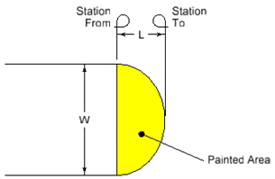
\(Painted Area = ½π × ½W × L\)
If the median is 7 ft wide and 3 ft long, the Station Length to enter under MNY4 would be:
\(½π × ½ × 7 ft × 3 ft = 16.5 ft2 (to determine area in ft2)\)
\(16.5 ft2 × 144 in2/1 ft2 = 2376 in2 (to convert area to in2)\)
\(2376 in2 ÷ 6 in wide paint line with a factor of 1.00 = 396 in\) (to convert area to inches of 6 inch paint line)
\(396 in ÷ 12 in/1 ft = 33 ft (to convert inches to feet)\)
\(33 ft ÷ 100 ft/1 Sta = 0.30 Sta (Sta length is two decimal places)\)
Channelizing Lines
For situations that do not call for separations in the roadway (traffic control, entrance/exit ramps, any others that do not have diagonal cross-hatching), use the appropriate Standard Roadway Condition above and replace the Edge Lines → Line Type with the corresponding channelizing line (CHW8 or CHY8). For those with additional diagonal cross-hatching channelizing lines, one of two methods described below will suffice:
Include both outer lines and the diagonals in one station to station run.
Direction of Travel → Either of the actual directions (if used in the center) or the actual direction (if used only on one side)
Side → L (if placement is center of roadway), L/C/R (if other)
Line Type → CHW8 or CHY8
Length of Marking → Amount calculated using another method (will be more than twice the amount shown in Length column)
Remarks column → “Includes lines and diagonals”
Separate outer lines and the diagonals into two station to station runs.
Outer Lines
Direction of Travel → BOTH (if used in the center) or the actual direction (if used only on one side)
Side → L (if placement is center of roadway), L/C/R (if other)
Line Type → CHW8 or CHY8
Length of Marking → Twice the amount shown in Length column (if lines are parallel) or split lines into two rows and use actual lengths (if lines are not parallel) or the amount shown in Length column if only one side of Diagonal Lines has Channelizing Lines.
Diagonal Lines
Direction of Travel → Actual direction
Side → L (if center placement), L/C/R (if other)
Line Type → CHW8 or CHY8
Length of Marking → Amount calculated using another method (will be different than the amount shown in Length column)
Remarks column → “Diagonal lines”
Uneven Lanes
When used in conjunction with TC-282 or TC-482, enter the following to indicate only part of the normal line work is to be placed:
Edge Lines
Direction of Travel → Actual direction of lift
Side → R
Line Type → ELW4
Length of Marking → Amount shown in Length column
Centerlines
Direction of Travel → Actual direction of lift
Side → L
Line Type → BCY4 or DCY4 or NPY4
Length of Marking → Amount shown in Length column
Remarks column → See TC-282 or TC-482 for sequencing
Back to top
108-23A
Traffic Control Plan
Special events that affect traffic are listed in this tab.
Back to top
108-23B
Traffic Control Closure Table(s)
This tabulation is intended to show when lane closures are not allowed. If a roadway does not have lane closure restrictions, this tabulation is not needed. The pictorial information shown should match what is described in the Traffic Control Plan (108-23A). The use of 108-23B should supplement 108-23A, not replace it. Tab 108-23A is not intended to provide stand-alone traffic control guidance.
Use the space above each table to indicate closure location information, including roadway, lane(s), stage, etc. Refer to 108-23B_example for a sample plan sheet.
The Lane Closure Planning Tool (LCPTOOL) is used to determine appropriate lane closure times for a given roadway. The LCPTOOL is available at https://secure.iowadot.gov/lcptool/Index.aspx.
Back to top
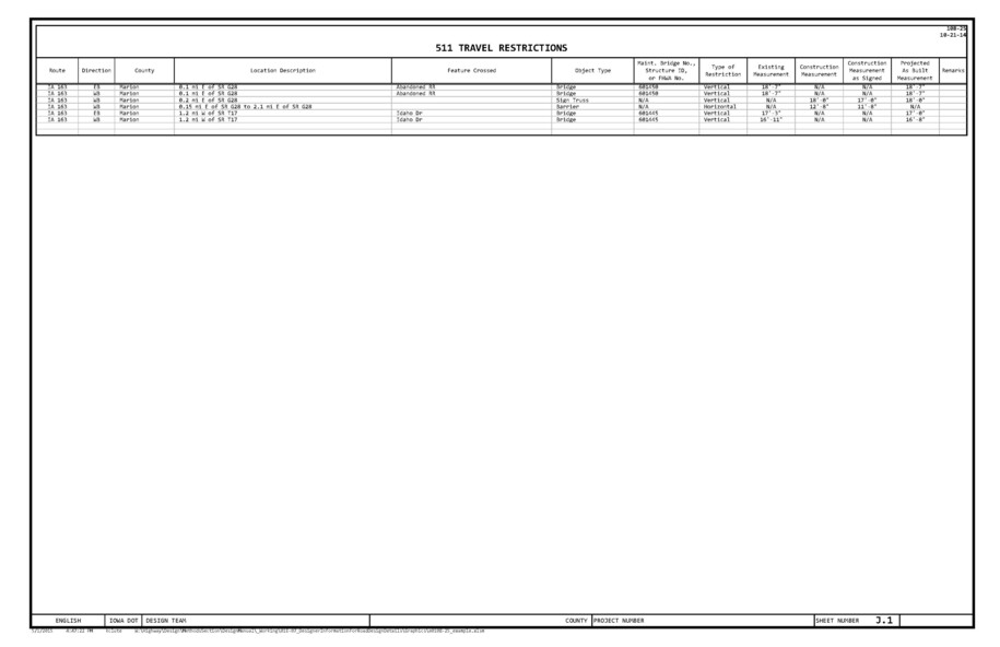
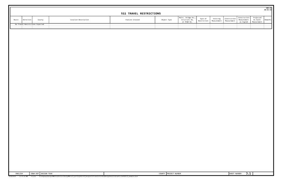
108-25
511 Travel Restrictions
The information shown on this tabulation is used by the Project Engineer (usually the RCE) to populate the CARS 511 request form to alert traffic of construction activities along our roadways. This information reflects the as-designed travel restrictions only. The Project Engineer will make any updates to the CARS 511 website as measurements, traffic control plans, or designated routes change in the field.
This tabulation only applies to work done on the associated plan sheets. Tied projects or work to be completed in another phase will have their own tabulation.
Please include the entire length of the project as well as any official detours. Should part of an official detour take place outside of Iowa, please contact the 511 team for that state through the “Links” drop-down list in the top right corner of the CARS 511 website. While the detour route will be highlighted on the Iowa 511 website through the route information provided in the CARS 511 request form, other State 511 websites are not automatically updated or notified. Since a detour route through another state already involves collaboration with a representative of that DOT, they are likely better suited to update their State 511 site. Please document their agreement to assist if they agree to do so.
This tabulation should initially be completed for the D2 Field Exam date. This will allow for discussion of any existing or planned projects not reflected in the tabulation. Check for updates before final turn-in.
Instructions and Explanation
A quick instruction and walk through for each column.
Route, Direction, County, Location Description, and Feature Crossed: These columns will be populated by the information shown in the following locations. Please compare the project and detour routes to each link and include any line of information that appears within the project boundaries, even if construction is not taking place at that item.
Vertical Clearance Restriction
Displays vertical clearance information for bridges on primary roads and primary road extensions. This report is published once a year by Research and Analytics.
Vertical Clearance Updates
http://www.iowadot.gov/mvd/motorcarriers/VerticalClearanceUpdate.pdf
Displays updates to the Vertical Clearance Restrictions report since the last publishing.
Vertical Clearance Log for Overhead Signs and Mast Arms
http://www.iowadot.gov/mvd/motorcarriers/VerticalClearanceLogforOverheadSignsandMastArms.pdf
Displays vertical clearance information for mast arms and sign trusses on primary roads. This report is published once a year by Bridges and Structures.
To assist in locating Overhead Signs and Mast Arms, a Google Earth file is available at https://documents.iowa.gov/#document=9593250. The identification markers match the Structure ID column in the pdf file.
|
| NOTE: The lists above do not include every mast arm over a highway. Mast arms maintained by cities are not inspected by Bridges and Structures are thus not in the available dataset. |
|---|
Vertical clearance restrictions from Temporary Signals are present whenever a temporary signal is part of the traffic control. This information is filled in by the designer by putting the milepost location (or range) in the Location Description column.
Horizontal clearance restrictions are present whenever lanes or shoulders are narrowed for construction purposes, likely by a barrier or another traffic control device. This information is filled in by the designer by putting the milepost location (or range) in the Location Description column.
Object Type: This column will typically be Barrier, Bridge, Mast Arm, Sign Truss, Temporary Signal, or Traffic Control Device.
Maintenance Bride No., Structure ID, or FHWA No.: This column comes from one of the first three reports shown above. Use the Maintenance Bridge Number on the Vertical Clearance Restrictions, the FHWA Number on the Vertical Clearance Updates, or the Structure ID on the Vertical Clearance Log for Overhead Signs and Mast Arms. For Barrier, Temporary Signal, and Traffic Control Device object types, place “N/A” for this column.
Type of Restriction:
For Bridge, Mast Arm, Sign Truss, or Temporary Signal, the type of restriction is vertical.
For Barrier or Traffic Control Device, the type of restriction is horizontal.
Existing Measurement:
For Bridge, Mast Arm, or Sign Truss, the existing measurement comes from one of the first three reports shown above.
For Barrier, Temporary Signal, or Traffic Control Device, the existing measurement is marked “N/A” unless they remain from a previous project.
Construction Measurement: These apply to the smallest clearance observed throughout the life of the project for that item. Do not provide a construction phase-by-phase breakdown.
Barrier: Measure horizontally from face of barrier to face of barrier.
Bridge, Mast Arm, or Sign Truss:
If traffic will not be allowed on the roadway during construction, mark this field “N/A”.
If traffic is allowed during construction, indicate the smallest vertical measurement observed. An example may be a bridge replacement and new alignment where the bridge is constructed first before the roadway is lowered.
Temporary Signal: Section 2528.03 states that for temporary traffic signals, “All signal heads mounted over the road surface are mounted to a minimum of 15 ft from the bottom of the signal head to the top of the road surface.” Use 15’-0” for the construction measurement in all cases.
Traffic Control Device: Measure horizontally from the lane location of the traffic control device (channelizers, drums, etc.) to the edge of traveled way during construction (may not be the normal edge of traveled way if traffic is allowed to drive on the shoulder).
Construction Measurement as Signed: This is typically 1’-0” less than the construction measurement for all vertical restrictions and 1’-0” less for horizontal restrictions narrower than 14’-6”, as shown on TC-81. If a horizontal restriction is 14’-6” or greater, mark this field “N/A”.
Projected As Built Measurement:
For Bridge, Mast Arm, or Sign Truss, use the following guidelines to generate the designed measurement:
Bridge - From the top of crown to the lowest point of the bridge over any lane in that direction.
Mast Arm - From the top of crown to the lowest point of the fixture over any lane in that direction.
Sign Truss - From the top of crown to the lowest point of the lowest sign as the signs are typically placed lower than the truss itself.
For Barrier, Temporary Signal, or Traffic Control Device:
If the item is to be removed before project completion, mark this field “N/A”.
If the item is permanent (barrier) or if it is to be left in place for a later project, use the same value as the construction measurement.
Sample Project #1
A 3 inch overlay project is taking place at the IA 163 Pella by-pass between County Road G28 and County Road T17. There are two interchanges, one at each county road, an abandoned railroad bridge near the G28 interchange, an overpass carrying Idaho Drive, and a new Sign Truss being constructed near the abandoned railroad. Because of work in the median and on the outside shoulder to install the sign truss, temporary barrier on both sides of the west bound lanes is required. While the project limits are between the two interchanges, the roadway underneath the abandoned railroad is not receiving the overlay. The tabulation for this project would be similar to Sample Project 1.
Sample Project #2
If a project is off the roadway and shoulder or involves work that does not include a horizontal or vertical restriction, the tabulation for the project would be similar to Sample Project 2.
Back to top
108-27
Temporary Floodlighting Luminaires
The contractor chooses which of the two options, trailer mounted LED or pole mounted, to use. The pole mounted option shows an offset. Offset is based on construction clear zone. This is entered into Tabulation 108-27 in the Offset column. Refer to Section 8A-2 for information regarding construction clear zone. The trailer mounted option can be placed at the edge of the shoulder.
Back to top
108-30
Crash Cushions
Please refer to 8C-5 for more information on Crash Cushions.
Back to top
108-33
Temporary Barrier Rail
Although TBR is laid out with a gap between segments, as shown on BA-401, TBR length is calculated as a multiple of 12.5. Gaps are not included.
Back to top
110-01
Removal of Pavement
If a project has either a Cement Treated Base (CTB) or an Asphalt Treated Base (ATB), removal is included with the pavement removal bid item in the Removal of Pavement tab. Include the following estimate reference note:
Removal includes Cement Treated Base (CTB) or Asphalt Treated Base (ATB) under the existing pavement. This material may be recycled back into the project if it meets the requirements for recycled materials.
If a project has Cement Treated Soil (CTS), the treated subgrade is removed using Class 13 Excavation. Include the following estimate reference note:
Removal includes Cement Treated Soil (CTS).
Back to top
110-12
Pollution Prevention Plan
|
| This tabulation is for use in projects with R sheets. |
|---|
The Pollution Prevention Plan (PPP) shell is available through the Calculation Files program under the Excel C Sheets seed file and then under tabulation 110-12. For those unfamiliar with how to create this tabulation, refer to the example videos below:
Excel_Calcfiles_FileSelectionandProjectInformation
Excel_Calcfiles_Add_RemoveDESheets
Once this tab has been imported into the project file, replace the bolded, non-descript text with project specific information.
Instructions and a worksheet are provided inside of 110-12 to assist in determining the Number of Acres, Soil Association Types, and Runoff Coefficient Number needed to complete the PPP. The information used to calculate those values comes from Design Manual 10D-1. Please see that section for additional information and links to aid in completing the PPP.
|
| Use the Add Data button in the header to replace text. Editing the text within the cells themselves will ruin the text alignment and could lead to missing information in the plans. |
|---|
Review the entire 110-12 tabulation for project accuracy. Although the text provided in the shell is sufficient for most PPP submittals, discrepancies may exist between the shell and project specific information. In addition, some projects may require stipulations beyond those covered by the PPP shell. The designer is responsible for locating and resolving discrepancies and providing additional information when necessary. This may require working with Roadside Development, the Office of Construction, and the Office of Location and Environment to ensure the PPP is complete and correct.
The DNR requires the PPP to be signed and a certification statement included. This signature covers the base PPP. The DOT has determined that the Engineer of record should sign the PPP. For projects completed by consultants or local agencies, a representative of the Department (typically the project manager) must also sign the PPP; therefore, two signature lines are provided on the PPP.
Back to top
110-12L
Pollution Prevention Plan
|
| Do not use this tabulation on projects where the DOT is the Contracting Authority. |
|---|
Tabulation 110-12L is for use by local public agencies only. The Pollution Prevention Plan (PPP) shell is available through the Calculation Files program under the Excel C Sheets seed file and then under tabulation 110-12L. For those unfamiliar with how to create this tabulation, refer to the example videos below:
Excel_Calcfiles_FileSelectionandProjectInformation
Excel_Calcfiles_Add_RemoveDESheets
Once this tab has been imported into the project file, replace the bolded, non-descript text with project specific information.
Instructions and a worksheet are provided inside of 110-12L to assist in determining the Number of Acres, Soil Association Types, and Runoff Coefficient Number needed to complete the PPP. The information used to calculate those values comes from Design Manual 10D-1. Please see that section for additional information and links to aid in completing the PPP.
|
| Use the Add Data button in the header to replace text. Editing the text within the cells themselves will ruin the text alignment and could lead to missing information in the plans. |
|---|
Review the entire 110-12L tabulation for project accuracy. Although the text provided in the shell is sufficient for most PPP submittals, discrepancies may exist between the shell and project specific information. In addition, some projects may require stipulations beyond those covered by the PPP shell. The designer is responsible for locating and resolving discrepancies and providing additional information when necessary.
The DNR requires the PPP to be signed by a public agency official, either the principal executive officer or the ranking elected official. If the design is completed by a consultant, the local public agency may want to consider also requiring the engineer responsible for preparation of the PPP to sign the PPP. Therefore, two signature lines are provided on the PPP.
Back to top
110-13
Delivery and Stockpiling
For guidance, see Design Manual 1G-6.
Back to top
110-14
Sanitary or Storm Sewer Abandonment or Removal
Refer to Standard Specifications Section 2503 for Storm Sewer and 2504 for Sanitary Sewer.
The following applies to both Sanitary and Storm Sewer selections:
- Calculate Length of Pipe if using Abandonment, Plug and Fill or Removal. Do not calculate Length of Pipe if using Abandonment, Plug Only.
- Calculate Fill Material if using Abandonment, Plug Only or Abandonment, Plug and Fill. Do not calculate Fill Material if using Removal.
Back to top
111-01
Coordinated Operations
If there are no known operations to coordinate, enter “None provided.” in this tab.
Back to top
112-05
Concrete Medians
Column Descriptions
Type
Replace X inch or X inch, dowelled with appropriate bid item value.
Modified Subbase versus Special Backfill
Use is determined by Pavement and Soils design.
Back to top
112-06
Bridge Approach Section
All paved shoulder panels are to be included on Tabulation 112-9. The square yard areas for the approach pavement in single reinforced and non-reinforced areas should only account for the widths of driving lanes.
Review project with the Bridges and Structures Methods Engineer to determine the appropriate abutment, approach, and abutting pavement types.
Special backfill is used only with BR-241.
Back to top
112-07
Rumble Strip Panels
To aid in selecting New or Existing under the Pavement column, use the following guideline:
Rumble strips can either be cut in existing pavement (which would include a resurfacing) or formed in new pavement (a full depth patch). If the rumble strips are being cut in, the pavement is existing. If they are being formed in a full depth patch, the pavement is new.
Back to top
112-09
Shoulders
For a list of available unit weights for use in the calculations note, as well as where to use them, refer to 1B-4.
The Hot Mix Asphalt (TON and TON/STA) and Binder (TONS) columns are for field and contractor information. Shoulders are bid by area, as shown by the bid item designation on the two Paved Shoulder (SY) columns, and Binder is incidental when HMA is bid by area.
In the column heading for Paved Shoulder at Guardrail, include the thickness. If different locations have different thicknesses, include the thickness in the Remarks column.
In the column heading for Subbase, specify the type of subbase. If different locations have different subbase types, specify the type in the Remarks column.
Back to top
112-10
Milled Rumble Strips
For a general overview of milled rumble strips and when to use them, see Design Manual 3C-5.
For designer information specific to Milled Shoulder Rumble Strips, see guidance for Standard Road Plan PV-12.
For designer information specific to Milled Centerline Rumble Strips, see guidance for Standard Road Plan PV-13.
Back to top
113-02
Pedestrian Path Closures
If using this tab, please include instructions regarding pedestrians in the Traffic Control Plan tabulation 108-23A located in the J Sheets. For additional information regarding what to include in the Traffic Control Plan, see 1F-10.
Type III Barricades are tabbed, but not bid. They are incidental to Traffic Control.
Back to top
113-10
Sidewalk Compliance
For Accessible Sidewalk Requirements, see Design Manual 12A-2.
Instructions and Explanation
A quick instruction and walk through for each column
Point: Use the following convention to name any point that has a change in length, width, or slope for each corner within every intersection:
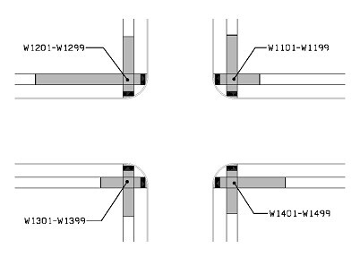
The second intersection will have numbering starting W2101-W2499 and so on.
Station, Offset, and Elevation: Populate as per standard procedure.
Point to Point: Type in the two points that are to be compared. It is critical that the points used are entered EXACTLY as they appear under the Point column.
Sidewalk Designation: A pull-down menu that allows the designer to select what piece of the sidewalk layout is designated by the two points selected in the Point to Point columns. This is a locked selection. If the designer feels that their piece is not one of the available selections, please contact the Design ADA Coordinator to discuss.
_″ PCC Sidewalk: Assumed based on typical depth for given Sidewalk Designation entry. Values may be changed for site conditions. Values are not locked. Type in a value if different.
Distance: The distance between the two points in the Point to Point columns. This can be a straight line if the points are oriented as such. In the case where the two points are on a curve, use the distance around the curve between the two points, rather than their straight line distance. Please note that this distance does not include curb, as indicated by the asterisk.
Δ Elevation: Calculates the change in elevation between the two points.
Slope: Calculates the change in slope between the two points by taking the value in the Δ Elevation column divided by the value in the Distance column.
Legally Acceptable Range: Provides the acceptable range in slope depending on the Sidewalk Designation column. Although these slopes are shown as positives, they can also be negative and still valid.
Acceptable Constructed Range: Provides the acceptable constructed range in slope.
If the difference between designed slope and the maximum legally acceptable range is greater than or equal to zero, it fills with the values provided in the legally acceptable range column. If the difference is less than zero, meaning the slope is beyond the maximum legally allowed, it fills with the minimum value provided in the legally acceptable range column and one percent higher than the designed slope. Although these slopes are shown as positives, they can also be negative and still valid.
Does Designer need to obtain design approval from Methods Engineer?: Fills with Yes if the Acceptable Constructed Range does not equal the Legally Acceptable Range or if Yes appears in the Staking Required column. This will be the case when the Difference column shows a negative number.
Staking Required on this Quadrant: Fills with Yes if Ramp Running Slope or Sidewalk Running Slope is selected in Sidewalk Designation column and the Slope is within 1% of the maximum allowed, or if Ramp Cross Slope or Sidewalk Cross Slope is selected in Sidewalk Designation column and the Slope is within 0.5% of the maximum allowed.
Measured Slope % and Initials: For the inspector to fill out in the field. The designer should leave these columns blank.
Remarks: Available for the designer to make remarks regarding the constructability of various points. Common remarks are available in a drop down. You are also able to write in one of your own, some examples are:
- This point is near the maximum allowable value.
- This point overrides the general specifications for the range selected.
- Cross slope of existing sidewalk is greater than 2%. Warp last section of sidewalk into existing sidewalk.
Also available for making remarks regarding corner radii or any additional information the contractor may need to construct a compliant design.
For Information Only: Provides the tab viewer with the information the designer entered in the Point, Station, Offset, and Elevation columns. These columns will automatically populate as the designer enters their information in. They were placed to the right of the blank column and beyond the remarks column to help suggest that these numbers cannot be guaranteed to be correct in the field. The actual constructor of the sidewalk is to use these numbers as a base but is ultimately responsible for adhering to ADA laws, not the points set in this tab.
Cell Formatting and Programming
Point column: If cell color is Yellow, the point is involved in ONE slope that is outside the acceptable range. If cell color is Orange, the point is involved in TWO slopes that are outside the acceptable range. If cell color is Red, the point is involved in MORE THAN TWO slopes that are outside the acceptable range.
Slope column: If the value calculated in the Slope column falls outside of the Acceptable Range for that sidewalk piece, the value will turn color to indicate that the design is out of compliance.
Sidewalk Design Adjustments
If any Slope column is highlighted, the design needs to be adjusted. It is suggested that the designer starts their adjustment by finding which Points are involved in the most out-of-compliance Slopes (see the color coordination above). By adjusting the “worst” Points first, one can potentially eliminate multiple Slope problems with minimal adjustment. By reducing the number of colored Points, one also reduces the number of Slopes out of compliance. The goal is to return the all the Point and Slope cell colors back to grey, and thus within all acceptable ranges, by adjust the Stationing, Offset, or Elevation points in the design. This will be a tedious process with multiple trials, but is necessary. If the designed layout cannot work in the theoretical model, it cannot be expected to work in the field.
Design Tips
In order to satisfy all the Slope requirements, one may have to think beyond just adjusting the elevations between points. Some suggestions include:
- Start with either your lowest form grade point intersecting with the sidewalk or the shortest leg on the ramp
- Add additional landings if the slope is too steep
- Move the sidewalk starting point further away from the intersection to create more room for the slopes to mature
- In some cases, the designation may need to change because the slope doesn’t fit in the designation’s range
- Landings may need to be placed at the back of curb when sidewalk is placed within 6 feet of curb. Use ramps to tie into to the existing sidewalk (if this approach is used, do not forget a landing at the top of the ramp).
No two layouts will be alike and all will require viewing sidewalk design as a puzzle with interchangeable pieces that allow for certain fluctuations. This is not a step-by-step thoughtless process, so do not view it as such.
Back to top
200s
All 200s
Back to top
2RP_
2 Lane PCC Ramp
Designers are to change the XX’ overall dimension to either 24’ or 26’ to match the mainline paving width. This change allows contractors to use the same paving setup on ramps as they did with mainline.
Back to top
Detour
Detour
This typical is not to be used for median crossovers.
PW is Pavement Width
SGW is Subgrade Width
T is Pavement Thickness
The 6-inch Special Backfill in Tons/Station column can be determined by flooding the area to get a cross-sectional square foot area and then multiplying by the following to convert to Tons/Station:
\[Value=Filled sf area*100ft/sta*140lbs/cf/2000lbs/ton\]
The 140 lbs/cf value comes from Design Manual 1B-4 for Special Backfill.
Refer to Design Manual 9C-6 for additional information.
Back to top
4DP_Raised_Crowned_
4 Lane Divided PCC with Raised Median - Crowned
The “_____ Subbase” material identifiers are generally either “Modified Subbase” or “Special Backfill”. Review project with Pavement and Soils design for which option to enter.
Back to top
4DP_Raised_Out_
4 Lane Divided PCC with Raised Median – Sloped Out
The “_____ Subbase” material identifiers are generally either “Modified Subbase” or “Special Backfill”. Review project with Pavement and Soils design for which option to enter.
Back to top
500-05
Precast Concrete Drain Extension
The most common use for this detail is in medians. It should not be used in areas where pedestrians will be present.
Back to top
500-10
Outlets for Longitudinal, Transverse and Backslope Subrains
This detail should be used only when the outlet will be in an area not subject to being run over by machinery such as mowers, or when the outlet is placed for temporary purposes. These outlets can be crushed by machinery, causing the subdrain to clog.
Back to top
510-04
Precast Stock Pass Extension
This detail is intended for extensions of existing stock passes only. For new stock pass installations, use a standard 6 foot x 7 foot precast box.
More information regarding stock passes can be found in Section 4B-2.
Back to top
560-04
HMA Wedge for Superelevation
Refer to the tables in Section 2A-3 to fill in e, L, and x in the Proposed columns in Tab 101-8.
The calculation for “m” is as follows:
Back to top
560-05
Painted Islands
Refer to section 6A-11 for Stop Sign Island information.
Jointing
For painted islands, square jointing is used instead of curved. Refer to Chapter 7A for PCC Pavement jointing guidelines.
Back to top
560-06
Shared-use Trail or Sidewalk behind Steel Beam Guardrail at Bridge Approach
As Road Design Detail 560-6 shows, a minimum of 2 feet is required behind the posts to the edge of the shared-use trail or sidewalk. This provides a shy distance for the users. It also helps to ensure the ends of the bolts used to mount the guardrail to the posts are located far enough away from the trail or sidewalk they do not present a hazard for the users.
An area behind the guardrail needs to be provided to allow the guardrail to deflect should it be impacted. For posted speeds of 45 mph or greater, 5 feet should be provided behind the face of the rail to the trail or sidewalk. For speeds less than 45 mph, this can be reduced to 4 feet.
Beyond the end of the trail, a minimum of 5 feet should be maintained between the edge of traveled way and the edge of a two-way shared use path (see page 3 of Section 12B-2).
Typically, the material between the roadway and the trail will be the same rock used for granular shoulders. Other surface options such as pavement or grass may be used if requested, but rock should be considered the default.
Back to top
570-01
Slash Mulch Berm
Slash mulch berms are typically used in place of silt fence ditch checks. Use of these is limited to contractor request, if allowed by the Engineer. Since these are used in place of silt fence ditch checks, no bid item or tabulation is available. Slash mulch berms should not be included unless specifically requested by the Roadside Development Section.
Back to top
570-08
Temporary Rock Berm for Sediment Control
This detail is intended for use with work areas adjacent to or in the water.
Silt fence should still be installed along the banks if room is available and installation is possible.
Floating silt fence can be used with this detail, but not in place of it. The DNR does not consider floating silt curtain as a primary form of erosion control.
Quantities are placed in Tabulation 100-23. See Table 2 in Section 1B-4 for Erosion Stone density.
Back to top
4317
Fill for Culverts Used for Bridge Replacement
Since floodable backfill costs less than flowable mortar, designers should look at using this detail, as opposed to Design Detail 4318, if possible. Designers will need to keep in mind that contractors need a minimum of 5 feet of vertical clearance to place floodable backfill. This means a minimum of 5 feet is required from the top of floodable backfill to bottom of beam or slab (depending on type of bridge).
Circle note 3 states 5 feet is the maximum distance from top of floodable backfill to bottom of beam or slab (based on the contractor’s need for a minimum 5 foot clearance). This is to minimize the amount of flowable mortar required, thus reducing cost. However, designers may encounter situations where maintaining 5 feet between top of floodable backfill and bottom of slab or beam results in a thin lift of floodable backfill (less than 2 or 3 feet). In cases such as these, using Design Detail 4318 may actually be more economical since the work required to place a thin lift of floodable backfill may outweigh the cost of using flowable mortar instead. As a guideline, when maintaining 5 feet between top of floodable backfill and bottom of slab or beam results in a lift of floodable backfill that is 4 feet or less, designers should investigate whether using Design Detail 4318 would be more economical.
Back to top
4318
Fill for Culverts used for Bridge Replacements with Restricted Height
Since floodable backfill costs less than flowable mortar, designers should look at using Detail 4317 if possible. Designers will need to keep in mind that contractors need a minimum of 5 feet of vertical clearance to place floodable backfill. This means a minimum of 5 feet is required from the top of floodable backfill to bottom of beam or slab (depending on type of bridge). If this is not possible, Detail 4318 will be required.
Back to top
6147
Transition between Curbed and Non-curbed Roadways
When a letdown flume is needed, refer to the scour protection details shown on DR-401.
Back to top
7148
Fillet for Non-Paved Entrances or Side Roads
The fillet width, F, is normally determined by survey or during field exam. In the case where it is not and no additional information is available, the following widths may be assumed:
For entrances, the fillet length, E, is 4 feet minimum.
Back to top
7149
Fillet Extension for Non-Paved Side Roads
When a construction or resurfacing project occurs on the primary system, counties have the option to add an additional 50 feet (or as agreed upon by the county and DOT) of paving along the secondary road at each granular secondary road intersection. This extension provides a paved area for the grader to stop without encroaching on the shoulder of the mainline.
Although constructed in conjunction with the mainline, the county is responsible for the initial cost and ongoing maintenance of the additional paving beyond the standard fillet(see sections 1.A.4 and 1.B.3 of Local Systems I.M. 7.110). For the purposes of this detail, the standard fillet is considered to be the paved shoulder width, or 6 feet from the edge of the through lane if the shoulder is not paved.
To separate out the quantity of pavement the county is responsible for, the additional amount of pavement (and associated items) placed in the fillet extension should be included as a second division of work within the PCC Pavement (100-24) or HMA Pavement (100-25) tabulations. This will also require the use of Estimated Project Quantities (Up to a 5 Division Project) tabulation (100-1C).
Since counties will need to add this into their budgets, they should be contacted as early in the design process as possible. The decision to add the fillet extension and values used for all variables shown is determined by the county at concept or field exam time.
Note that the L distance includes existing or constructed paved shoulder and existing fillets. Any pavement (and associated items, including subbase) quantities associated with the paved shoulder are to be shown on the Shoulders tabulation (112-9) and are not necessarily subject to a separate division of work.
This layout makes the assumption that the mainline is higher than the side road. If this is not the case (in a superelevated curve for example), Section A-A may be modified to show slopes necessary to meet conditions.
Back to top
7156
Paved Shoulder at Guardrail (Granular Shoulder Adjacent to Mainline)
(This section last updated 11-17-21)
The primary purpose of paved shoulder at guardrail is to provide a smooth, stable surface in front of guardrail for errant vehicles. However, it provides additional benefits:
- Reducing rock washout,
- Reducing mowing around guardrail installations, and
- Providing a strong enough pavement to eliminate the need for future shoulder strengthening.
This typical is not intended for use on bridge approaches for granular surface secondary roads passing over Primary or Interstate roadways.
The notes are set up for bidding alternate shoulders. If bidding PCC, remove the notes pertaining to the HMA alternative. Similarly, if bidding HMA, remove the notes pertaining to the PCC alternative.
At Bridge Ends (BA-250)
New Construction
For new construction, 6 inches of special backfill is placed under the pavement. Include 2_P_Guard_ for two lane roadways and 4_P_Guard_ for four lane roadways.
Existing Shoulder
For existing shoulder, pavement is placed on the existing surface unless the shoulder will need to carry traffic. If the shoulder will need to carry traffic, 6 inches of Special Backfill will be required beneath the pavement.
Pavement Thickness
The general note states to use 9 inch HMA Paved Shoulder (8 inch PCC may be substituted). For Interstates, modify the note in the typical to increase these to 11 inches HMA Paved Shoulder (9 inches PCC may be substituted).
If the shoulder pavement will need to carry traffic at some point in the future (e.g. traffic shifted for a bridge repair), the pavement may need to be thicker. Contact the Pavement Design Engineer for pavement thickness if the shoulder needs to carry traffic for 3 months or more and/or truck volume is greater than 1000/day (Primary) or 6000/day (Interstate).
Enter pavement thickness into Tab 112-9.
At Side Obstacles (BA-251 or BA-252)
New Construction
For new construction, 6 inches of special backfill is placed under the pavement. Include 2_P_Guard_ for two lane roadways and 4_P_Guard_ for four lane roadways.
Existing Shoulder
For existing shoulder, pavement is placed on the existing surface unless the shoulder will need to carry traffic. If the shoulder will need to carry traffic, 6 inches of Special Backfill will be required beneath the pavement.
Pavement Thickness
The general note states to use 9 inch HMA Paved Shoulder (8 inch PCC may be substituted). For protecting side obstacles, modify the note in the typical to decrease these to 7 inches HMA Paved Shoulder (6 inches PCC may be substituted).
If the shoulder pavement will need to carry traffic at some point in the future (e.g. traffic shifted for a bridge repair), the pavement may need to be thicker. Contact the Pavement Design Engineer for pavement thickness if the shoulder needs to carry traffic for 3 months or more and/or truck volume is greater than 1000/day (Primary) or 6000/day (Interstate).
Enter pavement thickness into Tab 112-9.
Back to top
7157
Paved Shoulder at Guardrail (Adjacent to Partial Width Shoulder)
The primary purpose of paved shoulder at guardrail is to provide a smooth, stable surface in front of guardrail for errant vehicles. However, it provides additional benefits:
- Reducing rock washout,
- Reducing mowing around guardrail installations, and
- Providing a strong enough pavement to eliminate the need for future shoulder strengthening.
The notes are set up for bidding alternate shoulders. If bidding PCC, remove the notes pertaining to the HMA alternative. Similarly, if bidding HMA, remove the notes pertaining to the PCC alternative.
At Bridge Ends (BA-250)
New Construction
For new construction, 6 inches of special backfill is placed under the pavement. Include 2_P_Guard_ for two lane roadways and 4_P_Guard_ for four lane roadways.
Existing Shoulder
For existing shoulder, pavement is placed on the existing surface unless the shoulder will need to carry traffic. If the shoulder will need to carry traffic, 6 inches of Special Backfill will be required beneath the pavement.
Pavement Thickness
The general note states to use 9 inch HMA Paved Shoulder (8 inch PCC may be substituted). For Interstates, modify the note in the typical to increase these to 11 inches HMA Paved Shoulder (9 inches PCC may be substituted).
If the shoulder pavement will need to carry traffic at some point in the future (e.g. traffic shifted for a bridge repair), the pavement may need to be thicker. Contact the Pavement Design Engineer for pavement thickness if the shoulder needs to carry traffic for 3 months or more and/or truck volume is greater than 1000/day (Primary) or 6000/day (Interstate).
Enter pavement thickness into Tab 112-9.
At Side Obstacles (BA-251 or BA-252)
New Construction
For new construction, 6 inches of special backfill is placed under the pavement. Include 2_P_Guard_ for two lane roadways and 4_P_Guard_ for four lane roadways.
Existing Shoulder
For existing shoulder, pavement is placed on the existing surface unless the shoulder will need to carry traffic. If the shoulder will need to carry traffic, 6 inches of Special Backfill will be required beneath the pavement.
Pavement Thickness
The general note states to use 9 inch HMA Paved Shoulder (8 inch PCC may be substituted). For protecting side obstacles, modify the note in the typical to decrease these to 7 inches HMA Paved Shoulder (6 inches PCC may be substituted).
If the shoulder pavement will need to carry traffic at some point in the future (e.g. traffic shifted for a bridge repair), the pavement may need to be thicker. Contact the Pavement Design Engineer for pavement thickness if the shoulder needs to carry traffic for 3 months or more and/or truck volume is greater than 1000/day (Primary) or 6000/day (Interstate).
Enter pavement thickness into Tab 112-9.
Back to top
7158
Paved Shoulder at Guardrail (Adjacent to Full Width Paved Shoulder)
The primary purpose of paved shoulder at guardrail is to provide a smooth, stable surface in front of guardrail for errant vehicles. However, it provides additional benefits:
- Reducing rock washout,
- Reducing mowing around guardrail installations, and
- Providing a strong enough pavement to eliminate the need for future shoulder strengthening.
Depending on the paved shoulder width, the pavement placed beyond the full width paved shoulder may be a narrow strip. However, it is still necessary in order to maintain a paved shoulder out to the guardrail. It does not need to be full depth if it is not expected to carry future traffic.
The notes are set up for bidding alternate shoulders. If bidding PCC, remove the notes pertaining to the HMA alternative. Similarly, if bidding HMA, remove the notes pertaining to the PCC alternative.
At Bridge Ends (BA-250)
New Construction
For new construction, 6 inches of special backfill is placed under the pavement. Include 2_P_Guard_ for two lane roadways and 4_P_Guard_ for four lane roadways.
Existing Shoulder
For existing shoulder, pavement is placed on the existing surface unless the shoulder will need to carry traffic. If the shoulder will need to carry traffic, 6 inches of Special Backfill will be required beneath the pavement.
Pavement Thickness
The general note states to use 9 inch HMA Paved Shoulder (8 inch PCC may be substituted). For Interstates, modify the note in the typical to increase these to 11 inches HMA Paved Shoulder (9 inches PCC may be substituted).
If the shoulder pavement will need to carry traffic at some point in the future (e.g. traffic shifted for a bridge repair), the pavement may need to be thicker. Contact the Pavement Design Engineer for pavement thickness if the shoulder needs to carry traffic for 3 months or more and/or truck volume is greater than 1000/day (Primary) or 6000/day (Interstate).
Enter pavement thickness into Tab 112-9.
At Side Obstacles (BA-251 or BA-252)
New Construction
For new construction, 6 inches of special backfill is placed under the pavement. Include 2_P_Guard_ for two lane roadways and 4_P_Guard_ for four lane roadways.
Existing Shoulder
For existing shoulder, pavement is placed on the existing surface unless the shoulder will need to carry traffic. If the shoulder will need to carry traffic, 6 inches of Special Backfill will be required beneath the pavement.
Pavement Thickness
The general note states to use 9 inch HMA Paved Shoulder (8 inch PCC may be substituted). For protecting side obstacles, modify the note in the typical to decrease these to 7 inches HMA Paved Shoulder (6 inches PCC may be substituted).
If the shoulder pavement will need to carry traffic at some point in the future (e.g. traffic shifted for a bridge repair), the pavement may need to be thicker. Contact the Pavement Design Engineer for pavement thickness if the shoulder needs to carry traffic for 3 months or more and/or truck volume is greater than 1000/day (Primary) or 6000/day (Interstate).
Enter pavement thickness into Tab 112-9.
Back to top
8101
Maintenance Turnaround
For radius information, refer to 3E-2 under Maintenance Turnarounds. Do not use entrance information in 3K-2.
\[Radius=Median Width/2-(2 * Shoulder Width)\]
Back to top
8208
Concrete Barrier with MSE Wall
The ‘W’ dimension varies depending on what is located behind the barrier. The minimum and preferred width is 2 inches. This may widen near overhead sign trusses, bridge abutments, or if there is an adjacent sidewalk. Discuss with Preliminary Bridge for locations and design considerations.
If ‘W’ is wider than 2 inches and near pedestrian areas, but the roadway does not have a sidewalk, consider placing fence or handrail on top of the concrete barrier for a couple of barrier sections prior to and beyond the widened area to deter pedestrians from walking outside of the barrier.
If there is sidewalk adjacent to the roadway, add fencing and sidewalk width to ‘W’. Refer to notes and details on bridge standards for sidewalk, fencing and handrail placement and design http://www.iowadot.gov/bridge/standards/english/EnglishDeckRailBridges.pdf.
Back to top
8210
Temporary Concrete Barrier Layout for One-Way Traffic
Although TBR is laid out with a gap between segments, as shown on BA-401, TBR length (L) is calculated as a multiple of 12.5. Gaps are not included.
Back to top
8212
Temporary Concrete Barrier Layout for Two-Way Traffic
Although TBR is laid out with a gap between segments, as shown on BA-401, TBR length (L) is calculated as a multiple of 12.5. Gaps are not included.
Back to top