
Content Information
On this page...
This section provides guidelines for access design and serves as a supplement to the Access Management Manual and Iowa Administrative Code 761—Chapter 112(306A,318). NCHRP Report 659: Guide for the Geometric Design of Driveways provides further guidance.
Prior to D5, submit plans with accesses to the Traffic and Safety Bureau for review. Section 1D-8 provides guidance on the access review submittal procedure.
According to the Access Management Manual, all exceptions require written justification. This will be handled by the appropriate District office. The District will note the justification in the access review letter.
Back to topAccess Types
Accesses are classified as Type A, Type B, Type C, or Type D based on traffic volume.
Type A
Type A is a private access connection with traffic volumes exceeding 100 trips in a peak hour. Volumes are based on the 20 year projection or the build out of a development, whichever is greater. Type A accesses are designed on a case-by-case basis. They are designed like city streets, with large returns, turning lanes, and traffic signals if needed. Geometric, staking, and jointing layouts may be required. Consideration of traffic volume impacts is required, and other operational treatments will be needed.
Type B
Type B is a private access connection serving moderate traffic volumes between 11 and 99 trips in a peak hour. Volumes are based on the 20 year projection or the build out of a development, whichever is greater. These accesses are considered light commercial accesses. Traffic volume impacts should be considered, and other operational treatments may be needed.
Type C
Type C is a private access connection serving light traffic volumes between 1 and 10 trips in a peak hour. Residential accesses are the typical Type C accesses.
Type D
Type D is a private access connection with an AADT of less than 1 trip per day. Type D accesses consist primarily of farm field accesses and accesses to utility vaults, boxes, valves, and other utility maintenance locations. For new construction or reconstruction projects, the farm field accesses should be designed to a minimum width of 30 feet to accommodate the increasing scale of farm vehicles using these accesses. For 3R projects that do not impact farm field accesses, no change in access widths is required as part of the project.
Back to topAccess Cases
In areas with curb and gutter, accesses are further classified as Case 1 or Case 2, based on return configuration. Case 1 accesses have radial returns. Case 2 accesses have flared returns. Standard Road Plan MI-210 is used. For Type B accesses, Case 1 is generally used, with Case 2 allowed only on low volume roadways. Type C and Type D accesses may use either Case 1 or Case 2.
Back to top
Access Design
Several factors should be considered for each access design including: available right-of-way; locations of adjacent accesses; mainline operating speed; anticipated traffic volumes of mainline and access; distance from intersections; sight distance; drainage conditions; accommodation for future sidewalk; ADA compliance of sidewalk; and other criteria considered pertinent by the designer.
Special consideration should be given to the land use of the property to be served by an access, particularly in cases of commercial accesses. In the design and location of an access, every effort should be made to perpetuate internal circulation patterns and avoid reduction of commercial value of the property being served.
Designers should also consider special vehicles, such as limousines or motorhomes, that may use an access to ensure appropriate widths and radii and ample vertical clearances exist for these vehicles.
Although Type A accesses are the only accesses that require case-by-case design, designers are encouraged to use turning templates or software to check all access designs.
Width and Radius
Type A access widths and radii are determined on a case-by-case basis. The typical design vehicle for a Type A access depends on surrounding land use and varies from a single-unit truck (SU) to a combination-type vehicle.
For Type B and Type C accesses, Tables 1 and 2 provide minimum and maximum values to be considered for access width “W” and paved radii “PR” or shoulder (granular) radii “SR”, see Standard Road Plans EW-501 or MI-210. The typical design vehicle for a Type B access is a passenger car (P) or single-unit truck (SU). For a Type C access, the typical design vehicle is a passenger car (P). For a Type D access, the design vehicle could be an SU, a tractor-trailer (WB-62), or farm machinery.
Designers should keep in mind that access width and radius are related: decreasing one may necessitate an increase in the other to maintain the same operating speed for the access; otherwise, drivers may be forced to reduce their speed appreciably to comfortably negotiate the access. This can lead to a significant speed differential between through and turning traffic, which can result in increased potential for crashes, especially for high volume roadways.
Back to topVertical Alignment
The algebraic difference, or breakover, between successive grades controls the vertical alignment of an access. Type A access grade and breakovers are determined on a case-by-case basis. The typical design vehicle for a Type A access depends on surrounding land use and varies from a single unit truck (SU) to a combination type vehicle.
For Type B, C, and D accesses, refer to Table 3 for preferred and acceptable maximum grade and break-overs. When breakovers exceed the preferred values in Table 3, scrapes on the pavement surface become common.
Excessive breakover from traveled way to access can lead to operational problems. As breakover increases, driver discomfort while traversing the breakover increases forcing drivers to slow appreciably at accesses. This can lead to a significant speed differential between through and turning traffic, which can result in increased potential for crashes, especially for high volume roadways.
Curbed Accesses
As Figure 1 shows, access profile (g2) should slope upward (positive grade) from the gutter line to the curb side of the sidewalk (if present). Breakover between the cross slope of the traveled way (g1) and the positive slope of the driveway (g2) should be limited to 9%.
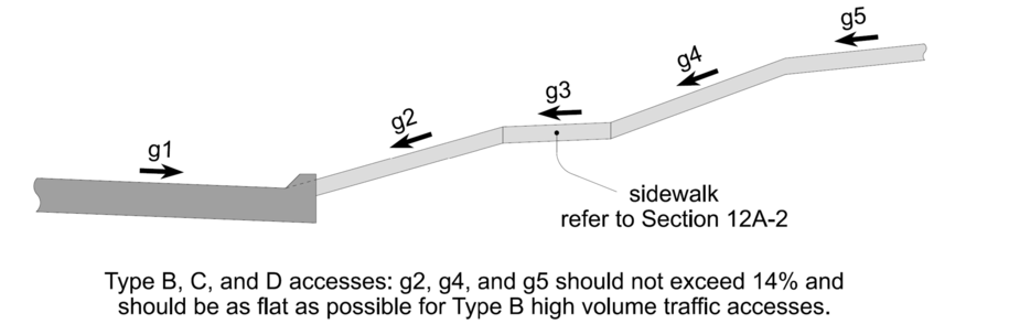
Figure 1: Typical curbed access profile.
Back to topUncurbed Accesses
As Figure 2 shows, access profile (g2) should slope downward (negative grade) and should be an extension of the shoulder grade (g1) for a distance sufficient to provide a safe platform for a vehicle to stop before entering the roadway. Twenty five feet is typical for a passenger car. A longer platform should be used if vehicles such as semitrailers or grain trucks will frequently use the access. The finished surface elevation of an access over a culvert, or the location where a culvert would normally be placed, should be lower than the primary highway pavement, preferably an extension of the shoulder grade. A minimum of 1 foot of cover is required over an access culvert.
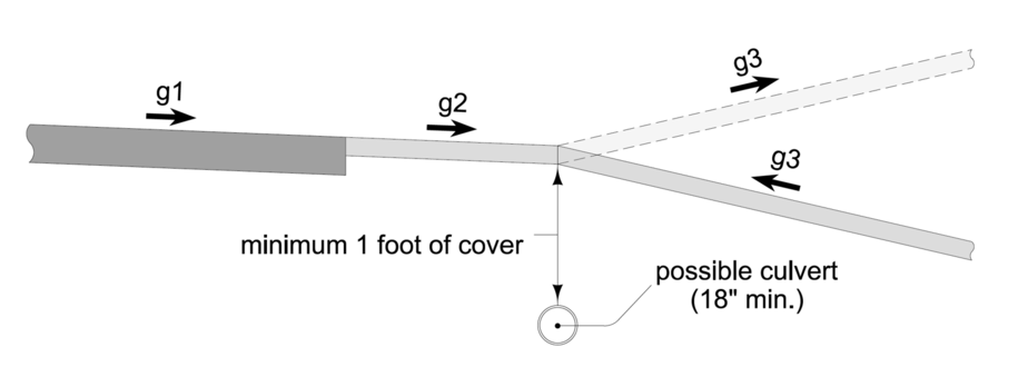
Figure 2: Typical uncurbed access profile.
Back to topDrainage
All accesses should be constructed so as not to impair drainage within the highway right-of-way, nor alter the stability of the highway subgrade. In addition, they should not impair or materially alter drainage of adjacent areas. All culverts, catch basins, drainage channels, and other drainage structures required under driveways as the result of property being developed should be installed according to current standards and specifications.
Back to topSurfacing
Curbed
All accesses in curbed settings should be paved to prevent aggregate from washing onto the pavement, curb, and gutters. If the existing drive is not paved, pave the first 10 feet from the back of curb or to the edge of the existing sidewalk. Consider additional paving beyond the sidewalk to prevent aggregate from washing onto the sidewalk.
Uncurbed
All accesses in uncurbed settings should be either paved or granular surfaced. If an access is to be granular surfaced, refer to Section 7C-1 for application rates.
Back to topApplicable Standard Road Plans
Curbed
Standard Road Plan MI-210 provides construction details for Type B, Type C and Type D curbed type accesses. Case 1 is used on most Type B accesses and on some Type C accesses in high speed areas. Case 2 is used on most Type C and Type D accesses, on Type B accesses where space is limited along the curb, on alleys and drives where the existing drive is too narrow, and in areas where no sidewalk exists. Special access details other than those shown on MI-210 should be included in the plans.

| Sidewalk cross slopes must fulfill the ADA requirements of Section 12A-2. Even if existing adjacent sidewalk is not being reconstructed, sidewalk cross slope through an access must fulfill ADA requirements. This may require replacing existing sidewalk through the access. Adjacent panels of sidewalk may need to be replaced to transition from access sidewalk to existing sidewalk
|
|---|
If the width of any existing access is less than the minimum for that type of access, consideration should be given to removing and replacing the existing access behind the sidewalk as shown for Case 2 in Standard Road Plan MI-210.
Uncurbed
Standard Road Plan EW-501provides construction details for most uncurbed type access. Special access details other than those shown on EW-501 should be included in the plans.
Curb Drop
Standard Road Plan PV-102 shows two choices for dropped curb height: 1.5 inch and 3 inch. Which curb height to use depends on several factors. A 1.5 inch curb is smoother to drive over and can be traversed at a higher speed, while a 3 inch curb results in a flatter slope for the drive and will better retain water in the gutter. For example, if a driveway slopes down from a roadway, a designer may choose to use a 1.5 inch curb since it is smoother to drive over; however, if water depth in the gutter is expected to exceed 1.5 inches, a 3 inch curb should be used to prevent water from running down the driveway. If a driveway slopes up from a roadway, a 3 inch curb may be used to help reduce the slope of the drive. This is especially important when designing an access that may be used by special vehicles such as limousines, semitrailers, or grain trucks, where it may also be necessary to lower the sidewalk grade to provide an even flatter slope.
A 1.5 inch curb should be used for commercial accesses with high volumes. Accesses designed in areas where vehicles are likely to traverse the curb at a high rate of speed should also be designed with 1.5 inch curbs. Normally, a 3 inch curb is used for residential accesses. A 1.5 inch curb may be used, but will result in a driveway with a steeper slope unless sidewalk grade is lowered.
Where applicable, consider the criteria set by the municipality to determine appropriate dropped curb height.
Back to topTabulating Accesses
Include Tabulation 102-3 in the plans. The Length of Opening columns should only be filled out for curbed type accesses.
Back to top