Content Information
On this page...
- General
- Design Criteria
- Type of Pipe
- Minimum Cover
- Minimum Vertical Drop at Structures
- Minimum Pipe Slopes
- Pipe Flow
- Sizing Pipes
- Design Velocity
- Time in Pipe
- HGL
- Outfall Conditions
- Tailwater Conditions
- Downstream Erosion Potential and Runoff Reduction
- Hydraulic Grade Line (HGL)
- Pressure Flow Design
- Check for Major Storms
- Intake and Manhole Sizing
- Circular Structures
- Rectangular Structures
- Filling in Tabulation 104-5B
- Design Documentation and Reporting
- Example Problem 4A-10_1, Pipe Velocity and Time
- Example 4A-10_2: Evaluation of System Time of Concentration
- Example 4A-10_3: Filling in Tab 104-5B
- Example 4A-10_3: Pressure Flow Problem 1
- Example 4A-10_4: Pressure Flow Problem 2
- Chart 4A-10_1 Flow Elements Chart
- Chronology of Changes
General
This section will assist in understanding the principles, assumptions, and design criteria required for storm sewer design to assist in computer modeling and checking.

| The Iowa DOT requires computerized modeling for drainage design. |
|---|
Computer modeling for drainage design is desired for many reasons including:
Facilitation of running and evaluating alternate design storms, scenarios, and criteria.
Evaluation of flow regimes. Hand calculations generally ignore or do not adequately evaluate junction losses at structures and/or velocity changes within pipes. Not all flows are subcritical, steady, uniform, etc. Models can help determine where flow regimes may be critical.
Evaluation of the hydraulic grade line (HGL) and tailwater conditions that are related to the previous bullet item as well as other constraints.
Facilitation in plan preparation and reporting.
Excel spreadsheets and hand calculations are useful for design checks; however, due to the various scenarios and flows required to be evaluated and the need to evaluate the HGL, spreadsheets and hand calculations should not be used as design tools.
Storm sewer systems are designed after intake types, locations, and sizes have been identified. The designer should consider such items as roadway classification, design traffic, cost, and safety (risk) in the design analysis. Placement and discharges of storm sewers should be designed to take into consideration potential damage to adjacent and downstream properties.
|
| Before beginning storm sewer design:
For pipes under railroads, contact Iowa DOT Office of Rail Transportation. |
|---|
For footing drains or other urban connections to the storm sewer system, refer to SUDAS design criteria.
A section of storm sewer connecting one intake or manhole to another is often called a “run” or “link”. A storm sewer system is designed from run to run. Design generally begins at the upstream end (or reach) of the system and proceeds down to the outlet. The process for determining the HGL begins at the outlet and works upstream. Downstream tailwater conditions – the water surface elevation of the receiving channel – may affect the design as well. Thus the overall design process is often iterative.
|
| Hydraulic design of storm sewer systems requires an understanding of basic hydrologic and hydraulic concepts and principles. Refer to HEC-22 Chapters 3 and 5 for a review of some basic hydraulic principles. This section assumes a basic understanding of these principles. |
|---|
Design of storm sewer systems generally assumes open channel flow for the minor storm event. To maintain open channel flow, the system must be sized so that the water surface remains open to atmospheric pressure (i. e. the flow depth is less than the pipe diameter). For this to happen, the HGL must be contained within the pipe. Consideration of pressure flow is allowed for the major storm event. In pressure flow, the hydraulic grade line will be higher than the pipe diameter.
Simple storm sewer design involves several assumptions such as steady and uniform gravity flow, junction losses in intakes and manholes, outlet conditions, etc. Equations and methods used for design are empirical and contain coefficients and assumptions. Existing systems should be investigated, evaluated, modeled, and calibrated before upgrading them or adding to them. An evaluation of the existing system profile along with an understanding of existing drainage concerns will assist in estimating the desired modeling extents. Design work and/or modeling may result in the determination of additional design/modeling needs.
Storm drains are expensive and permanent elements that are often very costly to replace, especially if replacement affects pavement, intakes, or other infrastructure. At a minimum, design models should be checked and verified by an individual experienced with storm sewer drainage design. When possible, alternate methods or models should be used to check designs. When results differ significantly between methods or models (more than 5 to 10 percent), the methods or models should be investigated to determine what may be causing the differences and why.
|
| Complex designs including but not limited to: detention basins, pump stations, complex networks, and/or systems with notable drainage concerns may require dynamic hydrograph routing computer modeling. Methods used for Dynamic modeling are to be approved by the Department for the specific project or task. |
|---|
Design Criteria
Design criteria are summarized below with more in-depth discussion following.
Location and Horizontal Alignment: Refer to discussion.
Type of Pipe: Assume concrete pipe with a Manning’s n = 0.013.
Minimum Pipe Size: 15 inch diameter. 24 inch diameter under Interstate pavement.
Minimum Cover: Refer to discussion.
Minimum Vertical Drop at Structures:
Equal pipe sizes: 0.3 feet is preferred, but 0.1 feet is allowed.
Changing pipe sizes: match soffit elevations.
Minimum Pipe Grades: For construction purposes, a slope greater than 0.4% is preferred. Initial estimates may use the average slope of the ground. Use 1% minimum grade for cross runs and stubs.
Pipe Flow
Assume 100% intake capture. Add possible bypass flow from other systems and off-site locations.
Minor Storm: Flow remains within pipe.
Major Storm: Pressure flow allowed if hydraulic grade line remains below intakes and manhole lids.
Pipe Friction Loss: Use 0.013 for Manning’s n for concrete pipe. Follow jurisdictional requirements for other pipe types.
Design Velocity
Within pipe system:
Minimum: 3 fps for cleaning velocity using a 5 year (Q5) recurrence interval.
Maximum: 15 fps calculated at the minor storm event and evaluated at the major storm.
Maximum Outfall Velocity: Refer to discussion.
HGL: Refer to discussion.
Crossings and Clearances (clearance is defined as outside of pipe to outside of pipe):
From Sanitary Sewer Mains: Minimum horizontal clearance is 5 feet. Minimum crossing vertical clearance is 6 inches with special structural support required at less than 18 inches. Clearance is defined as outside of pipe to outside of pipe.
From Water mains: Minimum horizontal clearance is 10 feet. Minimum crossing vertical clearance is 18 inches. Location and Horizontal Alignment
Design and place storm sewer with straight alignments between structures.
Parallel to street: Place storm sewer behind the curb as much as practical.
Transverse: Connect each end with to intake, manhole, or outfall.
Place public storm sewer systems located outside of the State right-of-way (ROW) in a storm sewer easement. Storm sewer easements should have a minimum width of 20 feet or two times the depth of the sewer (measured to bottom of trench), whichever is greater. The storm sewer should be centered in the easement. Additional width may be required by the Jurisdictional Engineer for maintenance purposes. Consideration needs to be given to future pipe repairs when considering easement locations and widths.
Where street layouts are curved with a radius of curvature greater than 200 feet and the storm sewer is 48 inches in diameter or greater, consideration may be made for a curved sewer using factory fabricated pipe bends. Consideration needs to be made for cost, available standard long radius curve sizes, and pipe industry recommended maximum deflection angle.
Refer to the SW Series of the Standard Road Plans for location stations of intakes and manholes.
Back to topType of Pipe
Design assuming concrete pipe. Concrete pipe is required under the pavement for all Primary and Interstate Highways, except non-NHS highways where ADT is less than 3,000. Assume a Manning’s roughness coefficient n = 0.013. Use the strength (class) and wall type required by the Standard Specifications and Standard Road Plans. The designer should evaluate the application with respect to the design fill height, ground water table, and other standard design considerations. Design examples in this section are based on concrete pipe. When a local jurisdiction allows another type of pipe outside of Primary Highway pavement, use SUDAS design criteria for the alternate pipe.
For trenchless installation, refer to Section 2553 of the Standard Specifications. For footing drain design considerations, refer to SUDAS for design criteria.
Back to topMinimum Cover
Under pavement: Top of pipe at least 1.0 foot below the bottom of subbase. If the pipe does not meet this requirement, adjust it until it does, or provide a design method to maintain the integrity of the pipe and pavement. Special design may include consideration of higher classification of pipe with flowable mortar backfill or other design measures.
Outside of pavement: 3.0 feet of cover is recommended. A minimum of 1.5 feet is required. Justification is required for less than 1.5 feet of cover.
Back to top
Minimum Vertical Drop at Structures
The flow line (invert elevation) of a pipe is located at the inside bottom of the pipe opening. The soffit (crown, overt) of a pipe is located at the inside top of the pipe.
To avoid trapping water, the Flow Line In elevation of a pipe taking flow from a structure should be lower than the flow lines of all upstream pipes entering the structure. Use the following criteria:
When the outgoing and incoming pipes are the same diameter, drop the flow line 0.30 feet where possible. A drop of 0.10 feet is allowed where 0.30 feet cannot be achieved.
When the diameter of the outgoing pipe is larger than the incoming pipes, align the soffits of the pipes. Where there are more than two inlets, generally the elevation of the soffit of the pipe leaving the structure will be aligned with the soffit of the largest pipe entering the structure.
These are the minimum elevation drops. On steeper grades, it may be necessary to make elevation drops larger in order to reduce the slope and keep water velocity under the scour velocity (15 ft/sec).
Back to topMinimum Pipe Slopes
Pipe velocity sets minimum slopes for storm sewer. However, for construction purposes, a slope greater than 0.4% is preferred. Initial estimates may use the average slope of the ground unless this would be unreasonable (such as in bluff areas). Use 1% minimum slope for cross runs and stubs.
Steep grades may result in flow transitioning from subcritical (tranquil) to supercritical (rapid) within a pipe, greatly affecting the velocity in the pipe. Caution and hydraulic understanding are required when working with pipes on steep grades. Computer modeling may assist in determining hydraulic issues and concerns.
Pipe slope is calculated using the difference between the inlet and outlet flowline elevations divided by the horizontal distance measured from inside wall of the upstream structure to inside wall of the downstream structure. The actual required length of a pipe for construction is calculated along the slope of the pipe. To make measurement easier for payment purposes, the Department measures along the ground from center of structure to center of structure. Therefore, the measured payment length is often different from the required installation length. The designer should ensure that pipe lengths used in the design provide the appropriate pipe design slope value, which in turn is used to determine the pipe design velocity and capacity.
Back to topPipe Flow
Maximum pipe flow capacity occurs at approximately 93% of the height of the pipe. This means that if the pipe is designed for full flow, the design will be slightly conservative. Pipe sizing should assume 100% capture at intakes. Do not decrease the size of pipe in the downstream direction, except for special situations such as detention or retention facilities. Software can help with determining initial pipe size estimates. Simple calculations may also be run using the procedure discussed in Sizing Pipes below.
As part of the storm sewer sizing analysis, evaluate bypass flow to other systems and impacts to those systems. When evaluating a portion of a system, be sure to include the flow contribution from the upstream watershed.
Special consideration may be required for pipes at sag locations. Sag intakes are designed assuming no plugging. Flanking intakes are added after the intake design is completed. Therefore the intake design analysis basically assumes no flow to the flanking intakes. For pipe design, the designer needs to assume the sag intake is completely plugged and 50% of its flow is captured in each of the two flanking intakes. Piping from flanking intakes should accommodate 100% of the flow to that intake plus 50% of any additional flow between that intake and the sag intake. This design requires inputting different design values into software to evaluate the different intake and pipe scenarios.
|
| Design pipes connecting flanking intakes and sag intakes assuming 50% of the flow to the sag intake is captured at each flanking intake (i.e. assume the sag intake is completely plugged). |
|---|
Sizing Pipes
Pipes are often evaluated using Manning’s Equation modified for circular pipes:
\(Q_{\text{full}} = \pi \left(\frac{K_u}{n}\right) \left(\frac{D^{2.67}}{4^{1.67}}\right) \sqrt{S}\) (Equation 4A-10_1)
where:
\(Q_{\text{full}}\)= Circular pipe full flow capacity, ft3/s.
S = Slope, ft/ft.
n = Manning’s roughness coefficient, Use 0.013 for concrete pipe.
Ku = Units conversion factor, 1.49.
D = Inside diameter of pipe, ft.
This equation does not account for things such as inlet or outlet control, pressure flow, special flow conditions, etc. The user should be familiar with the limitations of its use. For other pipe shapes refer to HEC-22.
To use Equation 4A-10_1:
Assume a pipe diameter and slope (or check an existing pipe)
Solve for \(Q_{\text{full}}\) , which is the estimated capacity of this pipe at full flow.
If \(Q_{\text{full}}\) is less than the design Q, adjust the slope, pipe size, or both until \(Q_{\text{full}}\) is greater than the design Q.
Because Equation 4A-10_1 has three independent variables (slope, diameter, flow), two of these variables may be known or assumed to solve for the third. Solving for D the equation becomes:
\(D = 0.263 \left( \frac{Q^{0.375}}{S^{0.1875}} \right)\) Equation 4A-10_2
Where Q may be the design flow and D and S are the same as in Equation 4A-10_1. To use Equation 4A-10-2:
Solve for D using the design flow and assumed or known slope.
Round the answer up to the next standard pipe size.
Back to top
Design Velocity
A self-cleaning velocity should be maintained to reduce the buildup of sediment that may lead to loss of capacity. For this reason, storm sewer systems are designed to maintain a minimum velocity of 3 ft/s or greater. This should be checked using a 5 year recurrence interval. This is most readily verified using computer modeling. In addition it is desirable to reduce junction losses and minimize flow transitions between subcritical and supercritical, which is why there is a maximum velocity value within systems (this is different than the maximum desired velocity at the outfall).
At the outlet:
With a flared end (apron) section: Maximum of 5 ft/s and evaluate downstream scour potential to determine if energy dissipation and/or scour measures are required.
With flared end section, footing and rip-rap, or other approved scour countermeasure: Maximum of 10 ft/s and evaluate downstream erosion potential.
With energy dissipation device: Maximum of 15 ft/s and evaluate downstream erosion potential.
Equation 4A-10_3 can be used to determine full flow velocity in a circular pipe (assuming full, steady, uniform flow):
\(V_{\text{full}} = \frac{Q_{\text{full}}}{A} = \left(\frac{K_u}{n}\right)\left(\frac{D}{4}\right)^{0.67}\sqrt{S}\) (Equation 4A-10_3)
where:
\(V_{\text{full}}\)= Velocity of full flow, ft/s.
A = End Area of pipe (πr2), ft2.
\(Q_{\text{full}}\), S, n, Ku, and D are the same as in Equation 4A-10_1.
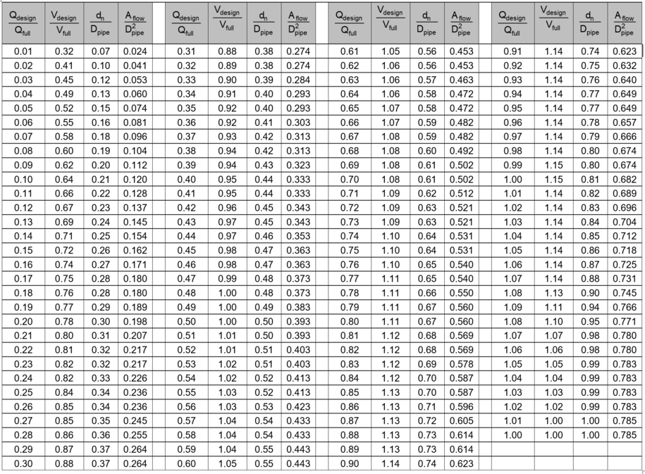
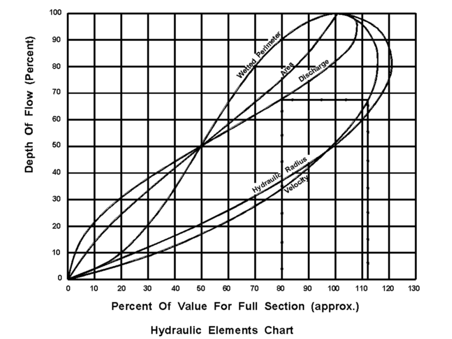
Partial pipe flow velocity can be much greater than the full pipe flow velocity, because at full flow there is more pipe friction acting on the water, thus slowing it down. As discussed under pipe flow, full flow is not to be confused with pressure flow. Computer modeling is the most efficient method to evaluate pipe velocity and the impacts that slope and pipe diameter have on it. The Flow Elements Chart can be used (as discussed below) to evaluate or estimate partial flow velocities in pipes. Adjust the diameter and slope until the partial flow velocity in the pipe falls between the minimum and maximum values.
Chart 4A-10_1, Flow Elements Chart
- Select a preliminary pipe size using known \(Q_{\text{design}}\)
Assume a slope (generally begin with ground slope).
Use Equation 4A-10_2 to solve for pipe diameter D.
Select a standard pipe size greater or equal to D.
Determine \(Q_{\text{full}}\) for the selected D.
Determine \(\frac{Q_{\text{design}}}{Q_{\text{full}}}\).
Using the result from step 6, look up \(\frac{V_{\text{design}}}{V_{\text{full}}}\) in the Flow Elements Chart.
Determine design flow velocity:
\(V_{\text{design}} = \frac{V_{\text{design}}}{V_{\text{full}}}\, V_{\text{full}}\)
The following example demonstrates the process.
Example Problem 4A-10_1, Pipe Velocity and Time
Back to topTime in Pipe
Time in Pipe (\(T_{\text{pipe}}\)) is calculated as:
\(T_{\text{pipe}} = \frac{L}{60\,V_{\text{design}}}\) (Equation 4A-10_4)
where:
\(T_{\text{pipe}}\) = time in pipe, minutes
L = Pipe Length, feet.
\(V_{\text{design}}\) = Design Velocity, ft/s.
Section4A-5 provides a worksheet and examples for calculating overland \(T_c\).
Example 4A-10_1, Pipe Velocity and Time
Time of Concentration (Tc) for pipe systems should consider and use the greater of:
\(T_c\) for the upstream intake plus time in pipe.
\(T_c\) for the intake.
Example 4A-10_2, Evaluation of System Time of Concentration
Back to topHGL
The HGL is a line coinciding with the water level in the system.
- For the minor storm, the HGL must be within the pipes.
- For the major storm, the HGL must be below intake form grade elevations and manhole lid elevations.
Outfall Conditions
All storm sewer systems have an outlet to which they discharge. The discharge point can be a natural stream, a ditch, an existing storm sewer system or culvert, or a proposed channel or system. AASHTO cautions, “Outfalls are the most downstream element in the storm drain system but should not be the last element to receive design attention” (Highway Drainage Guidelines, 4th Edition). The procedure for evaluating a storm sewer design begins at the outfall; therefore, consideration of outfall conditions is very important to storm sewer design. The following outfall conditions should be determined for each outfall before beginning storm sewer design:
- Outfall location. The discharge location may be into a receiving stream or an existing storm sewer system (open channel or closed conduit). Refer to Section 4A-4 for the Concept Plan. Consult with a drainage engineer before planning to discharge to an undefined swale, ditch, or stream.
- Outfall elevation. The storm sewer system outfall pipe flowline (also known as invert or inside bottom) elevation should not be below the receiving flowline elevation. For a receiving ditch or stream, the adjacent streambed flowline elevation should be evaluated for a determined distance (don’t just use existing survey data at the existing outfall) so that elevations in scour (erosion) holes are not used.
See Design Velocity for additional design criteria.
Once outfall conditions have been determined, tailwater conditions and downstream erosion potential can be evaluated.
Back to topTailwater Conditions
The design water surface elevation (design WSE) of the outfall is used in design to begin the HGL determination. The outfall design WSE must be estimated for the normal operating conditions of the storm sewer system and for alternate scenarios to assess risk of ponding or flooding potential. Determination of the design WSE and alternate scenarios requires knowledge of the outfall system watershed, storm sewer system watershed, and other factors and should be evaluated by someone knowledgeable in this design. Refer to AASHTO Highway Drainage Guidelines, 4th Edition, Chapter 9 for further consideration.
Back to topDownstream Erosion Potential and Runoff Reduction
HEC-14 notes, “Erosion at culvert outlets is a common condition. Determination of the local scour potential and channel erodibility should be standard procedure…” Discharge velocities are the main indicator of erosion potential and may be minimized by upstream storm sewer design considerations. Existing downstream erosion and/or flooding problems should be documented and evaluated.
Stormwater storage and/or energy dissipation may be required to protect an outfall, storm drain outlet, and/or downstream channel or property (including stream banks). Designers should evaluate existing concerns and other erosion indicators such as soil type, increase in discharge flow or volume over natural undeveloped discharges, etc.
HEC-14 discusses hydraulic design and energy dissipaters for culverts and channels. It also discusses flow transitions from pipe through flared end sections (aprons) and into channels. Chapter 5 of HEC-22 discusses stable channel design procedures and provides example problems for design and evaluation.
Refer to Section 4A-2 and Section 4A-4 for additional discussion on concept design considerations and documenting erosion potential and runoff reduction. Refer to SUDAS for erosion control and detention guidelines.
Back to topHydraulic Grade Line (HGL)
The HGL is a line coinciding with the water level in the system. It is used to determine the acceptability of a design, see HGL under Design Criteria. Computer modeling is ideal for HGL checks. For hand calculation checks, refer to Chapter 7 of HEC-22 for step by step guidance on estimating the HGL and for design examples.
Back to top
Pressure Flow Design
Pressure flow design requires that the flow in the pipe be at a pressure greater than atmospheric pressure. Under this condition the water surface in the structures (intakes and manholes) is above the top of the pipes. The significant difference between pressure flow and open channel flow is that the pressure head will be above the top of the pipe and will not equal the depth of flow in the pipe. In this case, the pressure head rises to a level represented by the HGL.
The hydraulic gradient can be roughly estimated using the following formula:
\(\text{Hydraulic Gradient} = \frac{\text{elevation}_{\text{upstream}} - \text{elevation}_{\text{downstream}}}{\text{length}}\)
where:
\(\text{elevation}_{\text{upstream}} = \text{may be ground surface or top of pipe, ft}\)
\(\text{elevation}_{\text{downstream}} = \text{generally the receiving stream or system WSE, ft}\)
Length = length between above elevation locations, ft
The hydraulic gradient may be checked across several pipes and structures (length may include several pipes and structures). This evaluation may be used for rough evaluation of existing systems, concept designs and for rough design checks. Use computer modeling to evaluate the HGL of a system for final design purposes.
The following two example problems illustrate the hydraulic gradient design check.
Example 4A-10_3, Pressure Flow Problem 1
Example 4A-10_4, Pressure Flow Problem 2
Back to topCheck for Major Storms
One of the last procedures in designing a storm sewer system is evaluation of and design for the major storm check. This generally includes design for the 100 year storm with consideration of overland flow paths for greater events. The major storm check is dominated by three concerns:
Ponding depth on primary highways is not to exceed 1 foot.
Residential dwellings and public, commercial, or industrial buildings are not to be inundated at the ground line unless they are flood-proofed.
Water is not to accumulate in areas where it creates an unacceptable safety hazard for motorists or pedestrians.
To avoid these situations, drainage structures may need to be installed that do not correspond to the normal design recurrence interval.
When examining the system for a major storm event, determine how excess water will be stored and how it will reach the outlet (e.g. stream, river, lake). When excess water cannot get into the storm sewer system, the individual intakes – or possibly the entire storm sewer system – must be resized. Designers must consider all overland flow paths the water may take during the major design storm and greater design events. Flowage easements may be required to maintain overland flow paths and to prevent construction and building in overland flowage areas. Evaluation of major storms and the need for overland flowage easements requires careful analysis due to the potential impact on surrounding property.
Back to topIntake and Manhole Sizing
Once storm sewer pipes are sized, intake and manhole sizing can be finalized. Refer to the Standard Road Plans for intake and manhole dimensions.
The placement and type of manhole depends on:
Location of traffic.
Depth of manhole.
Size of intercepting storm sewer pipe(s).
Skew of intercepting storm sewer pipe(s).
Other utilities.
Back to top
Circular Structures
Precast manholes come in standard sizes. For each installation, a minimum diameter is required to maintain the structural integrity. The general rule is to keep a minimum of 6 inches between blockouts for adjacent pipes. To evaluate this, the blockout sizes of and angles between adjacent pipes are required. Refer to Table 1 for standard blockout dimensions.
When two or more pipes are involved, adjacent pipes involving the most critical situation (the smallest angle and largest pipes) should be evaluated. If the critical situation is not apparent, then evaluate all situations involving adjacent pipes.
Back to topRectangular Structures
Standard rectangular structures do not accommodate all pipe sizes. Larger pipe sizes may require intake modification.
Most intake and manhole standards provide guidance on maximum depths. Table 2 provides guidance for those which do not.
Back to top
Filling in Tabulation 104-5B
When using letdown structures, calculate the exact length of pipe required for installation and adjust for elbows. Adjust flow lines accordingly. Round measurements to the next higher whole foot. If two types of pipe are used on the same structure, tabulate them on separate lines of the bid tabulation.
Back to topDesign Documentation and Reporting
Storm sewer system documentation and reporting is discussed in Section 4A-2. Designers should also include an analysis of HGL results.
Back to top
Example Problem 4A-10_1, Pipe Velocity and Time
\(\text{Determine } V_{\text{design}} \text{ and } T_{\text{pipe}} \text{ given:}\)
Pipe diameter: D = 15 inches (1.25 feet).
Pipe length: L = 275 feet.
Average slope: S = 0.008
\(Q_{\text{design}} = 3.22\ \text{ft}^3/\text{s}\)
n = 0.013
Solution:
Determine the pipe capacity using Equation 4A-10_1 (Section 4A-10):
\(Q_{\text{full}} = \pi\left(\frac{K_u}{n}\right)\left(\frac{D^{2.67}}{4^{1.67}}\right)\sqrt{S} = \pi \times \frac{1.49}{0.013} \times \left(\frac{1.25^{2.67}}{4^{1.67}}\right) \times \sqrt{0.008} = 5.77\ \text{ft}^3/\text{s}\)
Determine full flow velocity:
\(V_{\text{full}} = \frac{Q_{\text{full}}}{A} = \frac{5.77}{\pi\left(\frac{1.25}{2}\right)^2} = 4.70\ \text{ft/s}\)
Use the Flow Elements Chart (Section 4A-10) to determine the partial flow velocity,\(V_{\text{design}}\) :
\(\frac{Q_{\text{design}}}{Q_{\text{full}}} = \frac{3.22}{5.77} = 0.56\)
\(\frac{V_{\text{design}}}{V_{\text{full}}} = 1.03\)
\(V_{\text{design}} = \frac{V_{\text{design}}}{V_{\text{full}}}\, V_{\text{full}} = 1.03 \times 4.70 = 4.84\ \text{ft/s}\)
Determine the time in the pipe using Equation 4A-5_3:
\(T_{\text{pipe}} = \frac{L}{60V} = \frac{275}{60 \times 4.84} = 0.95\ \text{minutes}\) (round to 1 minute)
Discussion:
\(\text{Round } T_{\text{pipe}} \text{ to the nearest minute. If } T_{\text{pipe}} < 0.50 \text{ minutes, } T_{\text{pipe}} \text{ can be ignored.}\)
Back to top
Example 4A-10_2: Evaluation of System Time of Concentration
Find the greatest Time of Concentration (\(T_c\)) for each intake.
where:
\(TA_1,\ TA_2,\ TA_3,\ TA_4 = T_c \text{ for the area that matches the number of the intake the area drains}\)
\(T_{p1},\ T_{p2},\ T_{p3} = T_c \text{ for the pipe that flows out of intakes 1, 2, and 3}\)
\(T_1,\ T_2,\ T_3 = \text{Greatest time of concentration}\)
Use methods provided in Section 4A-5 to estimate surface flow Tc values.
The table below lists intakes with corresponding calculations used to determine the greatest concentration times. The figure beneath the table illustrates the Tc flow paths.
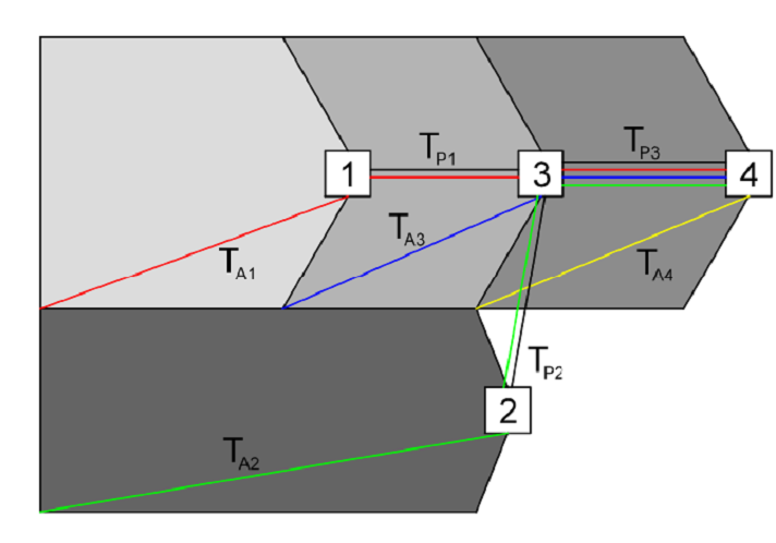
Add the time of concentration for the area and the time of concentration for the pipe draining into the intake. Repeat this process for each intake downstream, continuing the process for the entire system. For each intake, use the greatest time of concentration.
Back to top
Example 4A-10_3: Filling in Tab 104-5B
Tab 104-5B is included in the Plan for all storm sewer projects. It can be broken into two main components:
- Intake and manhole information.
- Pipe information.
Column 1 (No.)
For intakes, this number should be the same as the drainage area. For a manhole or outlet, assign an unused number.
Column 2 (Location)
See the Standard Road Plans for the location station on intakes and manholes.
Column 3 (Type)
See Section 4A-8 or 4A-9 to determine the type and size of intake. For aprons, choose one to fit the pipe and location and note any specifics. These selections need to be verified after final design of pipe sizing. Refer to the Standard Road Plans for minimum and maximum intake wall dimensions.
Column 4 (Form Grade)
Determine from profile grades, staking sheets, cross sections, and Standard Road Plans.
Column 5 (Bottom Well)
The bottom of the well will need to be completed after the flowline elevation for the pipe leaving the structure has been determined. See the Standard Road Plans and SUDAS Section 2M-3 for minimum and maximum depth requirements.
Column 6 (Extension Length)
Provide extension lengths used for SW-545.
Column 7 (Notes)
Provide notes to the contractor required to clarify structure design elements.
Column 8 (Pipe No.)
The pipe number should be the same number as the intake or manhole it drains. See Section 4A-4 for more details on numbering pipes.
Column 9 (Location of Pipe - From)
The number of the intake, manhole, or inlet located at the upstream end.
Column 10 (Location of Pipe - To)
The number of the intake, manhole, or outlet located at the downstream end. If the pipe is identified another way, state the specifics in the notes (e.g., outlet pipe into the side of RCB at Sta. 1+00, 20′ Rt.).
Column 11 (Class ‘D’)
For concrete pipes, use the strength (e.g., 2000D) required per standards and specifications.
Trenchless installation (See Section 2554 of the Standard Specifications).
Column 12 (Pipe Diameter)
Use the inside diameter of the pipe. For new initial designs, generally start with an estimated size based on known flow and then evaluate the design selection.
Column 13 (Bid Length)
The bid length is the length given in the bid tabulation for the basis of the contractors bid. It relates to the Basis of Payment and Method of Measurement sections of the Standard Specifications, which is measured from center of structure to center of structure. This length is generally not the same as the design length that is noted below. Round measurements to the next whole foot or to the nearest tenth of a meter (e.g., if the distance is 17.4 ft. use 18 ft.; if the distance is 5.31 meters, use 5.3 meters).
When using letdown structures, calculate the exact distance and adjust for elbows. Adjust flow lines accordingly. Round measurements to the next whole foot or to the nearest tenth of a meter. If two types of pipe are used on the same structure, tabulate them on separate lines.
Column 14 (Design Length)
The design length of a storm sewer pipe is the horizontal distance from the inside wall of the upstream intake (or manhole) to the inside wall of the downstream intake (or manhole). This length, along with the change in elevation from the inlet end to the outlet end, is used to determine the pipe slope and velocity.
Column 15 (Slope %)
For construction purposes, a slope greater than 0.4% should be used. For an initial estimate use the average slope of the ground.
The average ground slope can be found by using the following equation:
\(\frac{\text{Form Grade (FROM)} - \text{Form Grade (TO)}}{\text{Length between Form Grades}}\)
Column 16 (Flow Line Inlet Elevation)
The flow line inlet elevation is located at the inside bottom of the upstream end of the pipe (also known as the from node invert in GEOPAK).
To avoid trapping water, the Flow Line In elevation must be lower than the flow lines of all pipes entering the structure.
Column 17 (Flow Line Outlet Elevation)
The flow line outlet elevation is located at the inside bottom at the downstream end of the pipe (also known as the from node invert elevation in GEOPAK).
The Flow Line Out elevation can be found by using the following equation:
\(\text{Flow Line Out} = \text{Flow Line In} - (\text{Length} \times \text{Slope})\)
Column 18 (Flow Line Other)
Use this column for elbows or breaks in grade (e.g., a letdown structure). Note any specifics.
Column 19 (Pipe Profile Sheet No.)
This is provided for convenience in viewing the contract documents. Generally fill this out after design and plans are substantially completed.
Column 20 (Notes)
Provide notes to the contractor required to clarify pipe design elements.
Back to top
Example 4A-10_3: Pressure Flow Problem 1
Determine if the existing storm sewer pipe can be used in the new storm sewer design.
Given:
Discharge, Q = 40 \(ft^3/s\).
Pipe dimensions:
L = 300 ft.
Diameter = 24 inches.
Slope = 1.0%.
Solution:
Check the velocity assuming no pressure in the existing pipe:
\(V = \left( \frac{K_c}{n} \right)\left( \frac{D}{4} \right)^{0.67}\sqrt{S} = \left( \frac{1.49}{0.013} \right)\left( \frac{2}{4} \right)^{0.67}\sqrt{0.01} = 7.20\ \text{ft/s}\)
The velocity is acceptable.
Check the capacity:
\(Q = VA = V\left[\pi \frac{D^2}{4}\right] = 7.20\left[\pi \frac{2^2}{4}\right] = 22.6\ \text{ft}^3/\text{s}\)
The capacity of 22.6 \(ft^3/s\) is below the new storm sewer design discharge of 40 \(ft^3/s\). Check the capacity under pressure flow.
Use the required capacity (Q = 40 \(ft^3/s\)) to determine the needed hydraulic gradient:
\(40 = V\left[\pi \frac{2^2}{4}\right],\quad V = \frac{40 \times 4}{\pi \times 2^2} = 12.73\ \text{ft/s}\), which is less than the 15 ft/s maximum.
\(12.73 = \left( \frac{1.49}{0.013} \right) \left( \frac{2}{4} \right)^{0.67} \sqrt{S}, \qquad S = \left[ \left( \frac{12.73 \times 0.013}{1.49} \right)^{1.5} \left( \frac{4}{2} \right)^{0.67} \right]^2 = 3.1\%\)
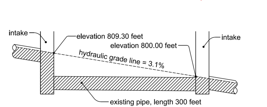
Calculate the elevation required to create the needed hydraulic gradient:
From Figure 1 above, the elevation in the downstream intake will be below the top of the existing pipe. Use 800.00 feet as the downstream elevation.
Determine the upstream elevation required to carry 40 ft3/s:
rise = length of existing pipe × hydraulic gradient = 300 × 0.031 = 9.30 feet.
upstream elevation = downstream elevation + rise = 800.00 + 9.30 = 809.30 feet.
If the elevation is above the form grade, the existing pipe will not work and will need to be replaced.
Back to top
Example 4A-10_4: Pressure Flow Problem 2
Determine the diameter pipe needed to prevent water from backing up during a major storm event.
Given:
Discharge, Q = 50 \(ft^3/s\).
Pipe length = 300 feet.
Water Surface Elevation in upstream pipe = 17 feet.
Water Surface Elevation (high water) of stream = 16 feet.
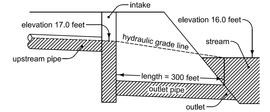
Solution:
Find the hydraulic gradient of outlet pipe (assume pressure flow in all parts of the outlet pipe):
\(\text{Hydraulic Gradient} = \frac{\text{elevation of water in upstream pipe} - \text{downstream water surface elevation}}{\text{length between elevation locations}} = \frac{17 - 16}{300} = 0.33\%\)
Using the hydraulic gradient as the slope, determine a pipe diameter (D) that can drain 50 \(ft^3/s\):
\(50\,\text{ft}^3/\text{s} = \pi \left( \frac{K_u}{n} \right) \left( \frac{D^{2.67}}{4^{1.67}} \right) \sqrt{S}, \qquad D = 3.3\ \text{ft}\ (39.6 inches)\).
Use a 42 inch diameter pipe.
Check that the velocity (V) is within limits for D = 42 inches:
\(V = \left( \frac{K_c}{n} \right) \left( \frac{D}{4} \right)^{0.67} \sqrt{S} = \left( \frac{1.49}{0.013} \right) \left( \frac{3.5}{4} \right)^{0.67} \sqrt{0.0033} = 6.0\ \text{ft/s}\)
This is between 3 ft/s and 15 ft/s, so the velocity is acceptable.
Back to top
Chart 4A-10_1 Flow Elements Chart
Chart 4A-10_1 Flow Elements Chart (189.84 KB) .pdf
Back to top