Content Information
On this page...
The processes are based on the procedures used in FHWA’s Urban Drainage Design Manual, Hydraulic Engineering Circular No. 22.
Other standard grate intakes (SW-501, SW-502, 503, 504, 505 and 506) are intended for use on the Secondary Road System and local streets, and should not be used on the Iowa DOT Primary Road System unless interagency agreements provide otherwise. When these grate intakes are used, design them according to the Iowa Statewide Urban Design and Specifications (SUDAS) design manual.
Back to topIntercepted Flow
Intercepted flow is flow intercepted by an intake under a given set of conditions. The interception capacity of a barrier grate intake is equal to the efficiency of the grate multiplied by the total gutter flow. The general equation relating efficiency to intercepted flow is:
\(Q_i = EQ\) (Equation 4A-8_1)
Where,
\(Q_i\)= Intercepted flow, \(ft^3/s\).
\(Q\) = Design gutter flow, \(ft^3\).
Back to topBypass Flow
Bypass flow is flow bypassing an intake. The general equation relating bypass to intercepted flow is:
\(Q_b = Q - Q_i\) (Equation 4A-8_2)
Where,
\(Q_b\)= Bypass flow, \(ft^3/s\).
\(Q_i\)= Intercepted flow, \(ft^3/s\).
\(Q\)= Design gutter flow, \(ft^3/s\).
Back to topEfficiency of Barrier Grate Intakes on a Continuous Grade
Efficiency is the percent of total flow that the intake will intercept under a given set of conditions. The efficiency changes with changes in pavement cross slope, longitudinal slope, and roughness, as well as total gutter flow.
The interception capacity of a barrier grate intake depends on:
Flow in the gutter section.
Flow velocity in the gutter.
Intake efficiency for barrier grate intakes is determined by the following equation:
\(E = R_f E_o + R_s(1 - E_o)\) (Equation 4A-8_3)
Where,
\(E\)= Efficiency.
\(E_o\)= Frontal flow to total gutter flow ratio.
\(R_f\)= Frontal flow interception.
\(R_s\)= Side flow interception.
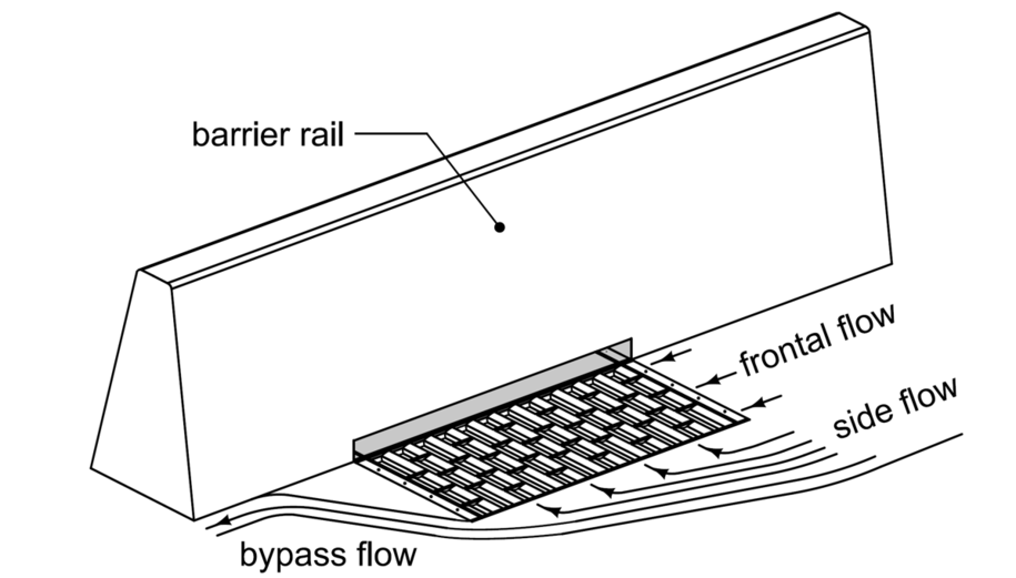
Figure 1: Grate intake flow definitions.
Barrier grate intakes on continuous grades should be placed to intercept no less than 50% of the minor storm design flow.
Back to topFrontal Flow to Total Flow Ratio
The ratio of frontal flow to total gutter flow for a uniform cross slope is determined using the following equation:
\(E_o = 1 - \left(1 - \frac{W}{T}\right)^{2.67}\) (Equation 4A-8_4)
where:
\(E_o\)= Ratio of frontal flow to total gutter flow, (\(Q_w/Q\)).
W = Width of grate, feet. Use 2.09, the width of the grate used with the SW-547, SW-548, and SW-549.
T = Total spread, feet.
Back to top
Frontal Flow Interception
As shown in Figure 1 above, frontal flow is the portion of the flow that passes over the upstream side of a grate. The ratio of frontal flow intercepted to total frontal flow, Rf, is determined using the following equation:
\(R_f = 1 - K_f (V - V_o)\) (Equation 4A-8_5)
where:
\(K_f\)= Empirical coefficient, 0.09.
V = Velocity of flow in the gutter, ft/s.
\(V_o\)= Gutter velocity where splash-over first occurs, ft/s (m/s). Use 8.3 ft/s, the splash-over velocity for the grate used with the SW-547, SW-548, and SW-549.
Velocity of flow in the gutter (V) is determined as follows:
\(V = \frac{2Q}{T^2 S_x}\) (Equation 4A-8_6)
where:
Q = Flow in gutter, \(ft^3/s\).
T = Spread, feet.
\(S_x\) = Cross slope of pavement, ft/ft.
Back to topSide Flow Interception
As shown in Figure 1 above, side flow interception is flow that is intercepted along the side of a grate intake. The ratio of side flow intercepted to total side flow, \(R_s\), is determined using the following equation:
\(R_s = \frac{1}{1 + \frac{K_s V^{1.8}}{S_x L^{2.3}}}\) (Equation 4A-8_7)
where:
\(K_s\)= Empirical Coefficient, 0.15.
V = Velocity of flow in the gutter, ft/s.
\(S_x\) = Cross slope, ft/ft.
L = Length of grate, ft. Use 3.33 feet, the length of the grate used with the SW-547, SW-548, and SW-549.
Once \(R_f\), \(E_o\), and \(R_s\) are determined, solve for E using Equation 4A-8_3 and then solve for \(Q_i\) and \(Q_b\) using Equations 4A-8_1 and 4A-8_2 as illustrated in the following example.
Example Problem 4A-8_1, Evaluate an SW-547 On-grade Median Barrier Grate Intake
HEC-22 provides additional guidance on how to evaluate and compare the interception capacity of intakes on grade.
Back to topBarrier Grate Intakes Located in Sags
When a barrier grate intake is located at the low point, or sag, of a vertical curve, the following procedures should be used to evaluate the intake:
Use a 50 year recurrence interval (2% chance storm) for the minor design storm.
Use a 100 year recurrence interval (1% chance storm) for the major design storm.
For the minor design storm, the intake needs to pick up 100% of the gutter flow from both sides at the maximum allowable spread.
In addition to checking the maximum allowable spread, check for roadway crown or curb overtopping and resulting overland flow.

| Ignore flanking intakes when evaluating barrier grate intakes in sags (refer to Section 4A-6 for more on flanking intakes). |
|---|
Check the spread on both sides of sag intakes. Use a longitudinal slope of 0.003 ft/ft (the minimum slope required to carry water in the gutter just before reaching the intake). If spread exceeds allowable encroachment, relocate or resize upstream intakes or add additional upstream intakes to reduce spread approaching the sag intakes.
Once the spread requirements on both sides of the intake are satisfied, verify the spread at the intake itself does not exceed allowable encroachment (see Table 1, Section 4A-6). The process for calculating spread at the intake is discussed in more detail at the end of this section. If spread at the sag intake exceeds allowable encroachment, relocate or resize upstream intakes to reduce spread at the sag intake.
A barrier grate intake in a sag location operates as either a weir (gravity controls flow) or an orifice (pressure controls flow) depending on the depth of the water at the grate. Barrier grate intakes typically operate as a weir up to a depth of approximately 0.4 feet, at which point flow begins to transition to orifice flow. In order to determine if a barrier grate intake is operating under weir flow or orifice flow, Equations 4A-8_9 and 4A-8_11 should be solved for a given intercepted flow (Qi). The equation resulting in the largest calculated depth determines the control type.
|
| When performing weir and orifice flow calculations for barrier grate intakes, assume the top of the grate is set at the same slope as the median. |
|---|
Weir Flow
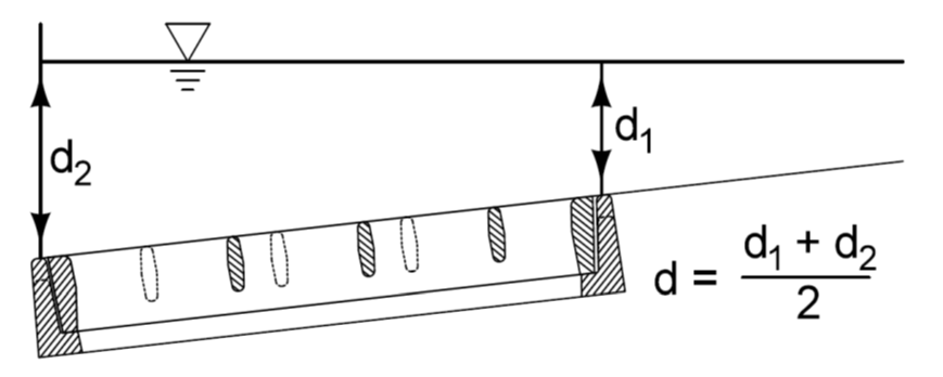
Weir flow is flow over a horizontal obstruction controlled by gravity. To determine weir flow, the average depth across the grate is needed. Figure 2 shows how this is determined.
The capacity of a barrier grate intake operating as a weir is:
\(Q_i = C_w P d^{1.5}\) (Equation 4A-8_8)
where:
\(Q_i\)= Intercepted flow, \(ft^3/s\).
\(C_w\)= Weir coefficient, 3.0.
P = Perimeter of the grate (disregarding the side against the curb, ft). Use 7.52 feet, the perimeter, disregarding the side against the curb, for the grate used with the SW-547, SW-548, and SW-549.
d = Average depth across the grate, feet.
Rearranging Equation 4A-8_8 and solving for d yields:
\(d = \left( \frac{Q_i}{C_w P} \right)^{\frac{2}{3}}\)
Where,
d, \(Q_i\), \(C_w\), and P are as defined above.
Back to topOrifice Flow
Orifice flow is the flow of water into an opening that is submerged. Pressure forces control the flow. The capacity of a barrier grate intake operating as an orifice can be approximated as:
\(Q_i = C_o A_g \sqrt{2gd} + C_o hL \sqrt{2g\left(d - \frac{h}{2}\right)}\) (Equation 4A-8_10)
where:
\(Q_i\) = Intercepted flow, \(ft^3/s\).
\(C_o\) = Orifice coefficient, 0.67.
\(A_g\) = Clear opening area of the grate, ft2. Use 2.3 ft2, the clear opening for the grate used with the SW-547, SW-548, and SW-549.
g = Gravity, 32.16 \(ft/s^2\).
d = Depth at the curb, feet.
h = Height of opening. Use 0.25 feet, the height of the opening for the SW-547, SW-548, and SW-549.
L = Length of opening. Use 3.33 feet, the length of the opening for the SW-547, SW-548, and SW-549.
Solving for d requires a trial and error process.
Once depth has been determined, use the equation below to approximate spread at the intake:
\(T = \frac{d}{S_x}\) Equation 4A-8_11
where:
d = Depth determined by either equation 4A-8_9 or 4A-8_10, feet.
\(S_x\) = Cross slope, ft/ft.
Example Problem 4A-8_2, Barrier Grate Intake in a Sag
Back to top
Example Problem 4A-8_1, Evaluate an On-Grade SW-548 Barrier Grate Intake
Determine intercepted and bypass flows by calculating the efficiency of an on-grade SW-548 barrier grate intake located on an Interstate highway. Shoulder width is 12 feet.
Given:
Cross slope: \(S_x\) = 0.03 ft/ft.
Manning’s coefficient for new pavement: n = 0.016.
Total flow rate: Q = 1.6 \(ft^3/s\).
Longitudinal slope: SL = 0.02 ft/ft.
Solution:
Use Equation 4A-6_4 from Section 4A-6 to find the gutter spread (T) directly upstream of the intake:
\(T = \left[\frac{nQ}{K_u\, S_x^{1.67}\, \sqrt{S_L}}\right]^{-0.375} = \left[\frac{0.016 \times 1.6}{0.56 \times 0.03^{1.67} \times \sqrt{0.02}}\right]^{-0.375} = 5.89\ \text{feet}\)
Allowable spread is the shoulder width of 12 feet. Gutter spread is less than allowable spread, so spread is acceptable.
Use Equation 4A-8_4 to calculate the grate frontal flow to total gutter flow (\(E_o\)):
\(E_Q = \left[1 - \left(1 - \frac{W}{T}\right)^{2.67}\right] = \left[1 - \left(1 - \frac{2.09}{5.89}\right)^{2.67}\right] = 0.69\ \text{or}\ 69\%\)
Use Equation 4A-8_6 to calculate the average gutter velocity (V):
\(V = \frac{2Q}{T^2 S_x} = \frac{2 \times 1.6}{5.89^2 \times 0.03} = 3.08\ \text{ft/s}\)
Use Equation 4A-8_5 to calculate the frontal flow interception (\(R_f\)):
\(R_f = 1 - K_f (V - V_o) = 1 - 0.09(3.08 - 8.3) = 1.47 > 1.0\)
Since the frontal flow interception (\(R_f\))is greater than 1.0, use \(R_f\) = 1.0
Use Equation 4A-8_7 to calculate the side flow interception (\(R_s\)):
\(R_s = \frac{1}{\left[1 + \frac{K_s V^{1.8}}{S_x L^{2.3}}\right]} = \frac{1}{\left[1 + \frac{0.15 \times 3.08^{1.8}}{0.03 \times (3.33)^{2.3}}\right]} = 0.296\ \text{or}\ 30\%\)
Use Equation 4A-8_3 to calculate the efficiency (E):
\(E = R_f E_o + R_s(1 - E_o) = (1 \times 0.69) + 0.296(1 - 0.69) = 0.78\ \text{or}\ 78\%\)
This exceeds 50%, so intake location is appropriate.
Use Equation 4A-8_1 to calculate the intercepted flow (\(Q_i\)):
\(Q_i = E Q = 0.78 \times 1.6 = 1.25\ \text{ft}^3/\text{s}\)
Use Equation 4A-8_2 to calculate the bypass flow (\(Q_b\)):
\(Q_b = Q - Q_i = 1.6 - 1.2 = 0.35\ \text{ft}^3/\text{s}\)
Discussion:
Efficiency exceeds 50%, so the designer could choose move the intake further downstream to increase distance between intakes and potentially reduce the number of intakes. However, intakes immediately upstream of a sag should be placed to achieve a higher efficiency to reduce bypass to the sag intake.
This example ignores the effect of clogging. Clogging is typically not an issue with barrier intakes located on rural facilities, which tend not to accumulate debris (e.g. leaves and branches). However, in an urban area, debris from landscaping, as well as trash (e.g. food wrappers and pop cans/bottles) can lead to clogging, and in these areas designers may want to consider a including a clogging factor as part of their intake calculations.
Back to top
Example Problem 4A-8_2, Evaluate SW-549 Installed in a Sag
Determine if an SW-549 barrier grate intake will function sufficiently for a 50 year storm.
Given:
Maximum allowable spread, T = 8 feet.
Flow from left side of intake \(Q_L\) = 1.05 \(ft^3/s\) .
Flow from right side of intake \(Q_R\) = 0.88 \(ft^3/s\).
Manning’s coefficient for new pavement: n = 0.016.
Cross slope: \(S_x\)= 0.03 ft/ft.
Solution:
Total flow \(Q_i = Q_L + Q_R = 1.05 + 0.88 = 1.93\ \text{ft}^3/\text{s}\)
Start by assuming weir flow. Use Equation 4A-8_9 with P = 7.52 ft (the perimeter of a Type S grate) to solve for average depth (d):
\(d = \left( \frac{Q_i}{C_w P} \right)^{2/3} = \left( \frac{1.93}{3.0 \times 7.52} \right)^{2/3} = 0.19\ \text{feet}\)
This is less than 0.4 feet, so the assumption of weir flow is correct.
Approximate the spread (T) at the grate using Equation 4A-8_12:
\(T = \frac{d}{S_x} = \frac{0.19}{0.03} = 6.33\ \text{feet}\)
This is less than the maximum allowable spread of 8 feet, so an SW-549 is adequate.
Discussion:
The designer will need to check spread to the left and right of the intake to verify they are less than allowable spread.
The designer will also need to verify this intake will function sufficiently for a 100 year storm. For the 100 year storm, encroachment must not exceed that allowed by Table 1 of Section 4A-6. In addition, the designer needs to check for potential roadway crown or curb overtopping.
This example ignores the effect of clogging. Clogging is typically not an issue with barrier intakes located on rural facilities, which tend not to accumulate debris (e.g. leaves and branches). However, in an urban area, debris from landscaping, as well as trash (e.g. food wrappers and pop cans/bottles) can lead to clogging, and in these areas designers may want to consider a including a clogging factor as part of their intake calculations.
Back to top