Content Information
On this page...
Setup for the DSN File for R Sheets
Use the Copy Seed function to create the R Sheet DSN file using the OpenRoads 2D Design File seed (see Section 21C-54 for more on the Copy Seed program).
For Projects using Survey Data
Attach the following items. Refer to Section 21A-50 for attaching references.
DSN file containing Road Design linework elements. This will be created by Design or District Design.
DSN file containing shading elements. This will be created by Design or District Design.
Statewide LiDAR for your project location. Design and District Design will need to place a request to Photogrammetry if one does not already exist for the project. Photogrammetry will provide a clipped down LiDAR for the project location.
Statewide NAIP or aerial imagery (RAS) for your project location. Photogrammetry will provide this.
Photogrammetry DSN (PHO) if one is available. Photogrammetry will provide this.
Survey DSN (SUR). Either Preliminary Survey or District Survey will provide this.
For Projects with No Survey using As Builts
Attach the following items. Refer to Section 21A-50 for attaching references.
DSN file containing Road Design linework elements. Either Design or District Design will create this.
DSN file containing shading elements. Either Design or District Design will create this.
Statewide LiDAR for your project location. Design and District Design will need to place a request to Photogrammetry if one does not already exist for the project. Photogrammetry will provide a clipped down LiDAR for the project location.
Statewide NAIP or aerial imagery (RAS) for your project location. Photogrammetry will provide this.
Photogrammetry DSN (PHO) if one is available. Photogrammetry will provide this.
DSN containing the As Built PDFs if available. This is done by finding the As Builts in ERMS and manually placing them in the plan (see Section 21C-56 for attaching PDFs to a MicroStation file).

| To properly control the display for sheeting, create a _PPP and a _BASIN file. |
|---|
Erosion Control Design
Determining Storm Water Detention Need
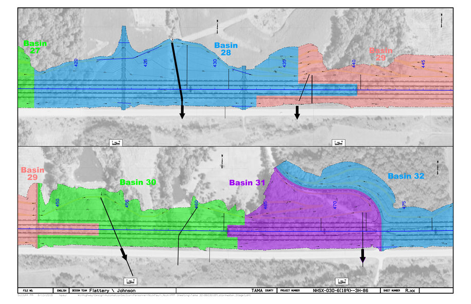
Drainage basin limits (see Section 10C-2)
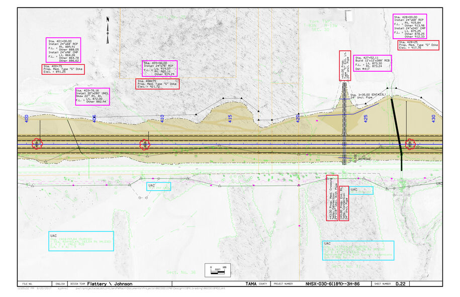
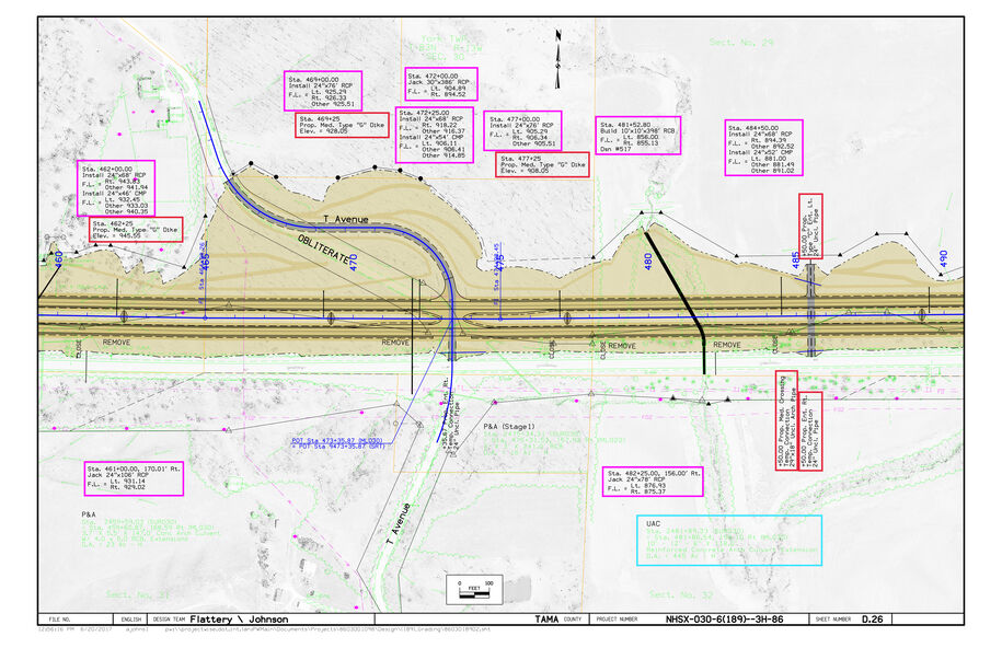
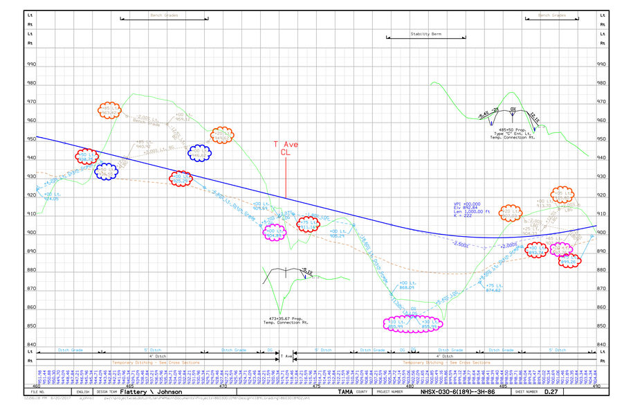
Use the plan and profile sheets (see Section 1F-5b) to locate the high spots that will determine the separation between the individual basins and the low spots of where the water will discharge.
- Do this for the left, right, and median ditch grades if present.
- Repeat this if necessary for intersecting sideroads.
- Sketch lines using the crests and other plan sheet information to form each drainage basin.
- Take into consideration existing and proposed roadway, median, and entrance culverts/pipes when determining how the water is being directed off the site through each basin.
- Take into consideration proposed and existing dikes, entrances, and intersection roadways when determining how the water is being directed off the site through each basin.
- Sample Plan and Profile.
-
-
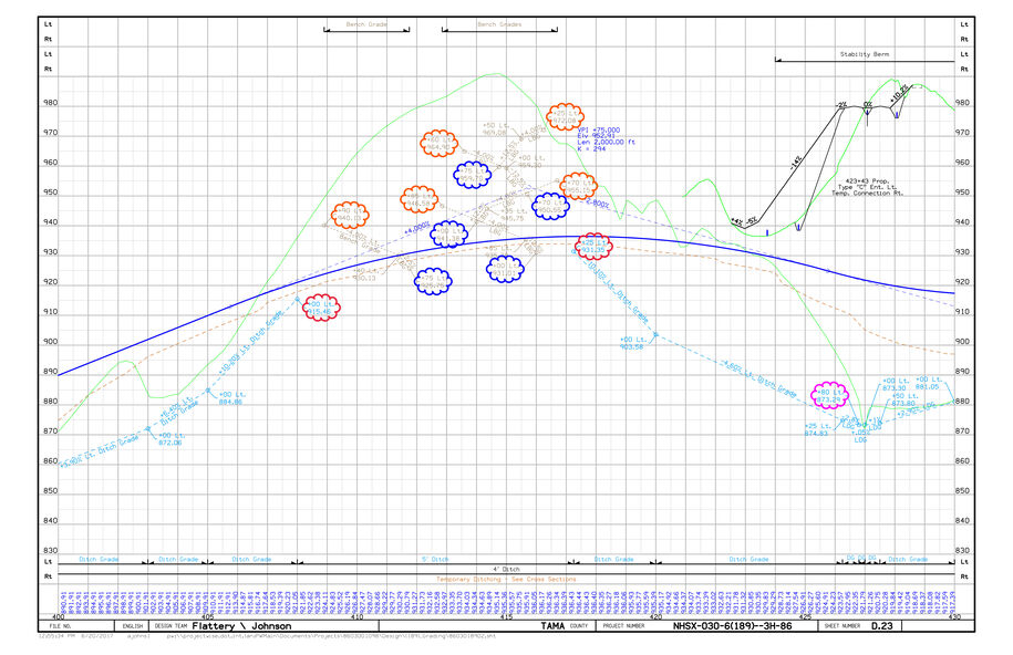
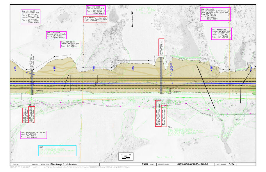
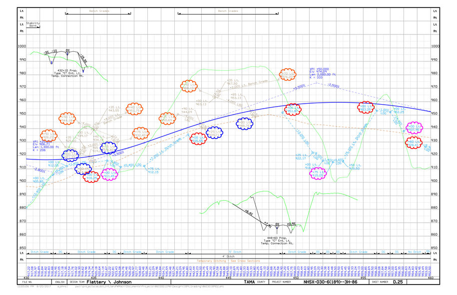
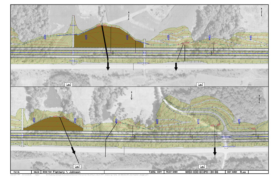
Place flow arrows and outlet arrows following ditching where there will be concentrated water flow. These will start at the highest point and be drawn toward the outlet of each basin or a draining pipe/culvert into which it drains.
- Place outlet arrows at locations where water will exit the basins in a concentrated flow.
- Show sheet flow where water will exit the construction site in a nonconcentrated flow.
Erosion Control Device Placement
Using the guidance in Section 10C-1, place erosion control measures in the following order:
- Silt Basins
- Rock Ditches
- Rock Check Dams
- Turf Reinforcement Mats (TRM’s)
- Silt Fence for Ditch Checks
- Silt Fences
- Temporary Sediment Control Basins
- Slope Protection
- 10 inch waddles
- 12 inch waddles
- 20 inch logs
- Perimeter Protection
- 10 inch waddles
- 12 inch waddles
- 20 inch logs
- Inlet protection
- 12 inch waddles
- Inlet sediment bags, see Section 10C-4
Vegetated buffers may be used with the guidance of Section 10C-3.
For urban and transitional areas, see Section 10C-5.
Final Erosion Control Measures
Once all erosion control devices have been placed, contract Roadside Development for final quantities and locations for seeding, fertilizing, and mulching. See Section 10B-1 for more information regarding seeding, fertilizing, and mulching.
Back to topR Sheet Creation
Create the Erosion Control Device Placement Set of RR Sheets
These will show the erosion control device placement and drainage arrows. Follow the sequence below:
Place port shapes for sheeting using one of the following:
Use the existing sheet ports from the D, E, or F sheets if available.
Use the Plan and Profile sheeting tools (see Section 21B-4) if a BPK or alignment is available.
Place them by hand if no other option is available.
Place scale blocks and north arrows if needed.
Run the Motif Builder tool from the D&C Manager (see Section 21B-2).
Clip the sheets using the D&C Plan and Profile Sheeting Tool and Motifs (see Section 21B-4).
Open the Erosion Control Device Placement set of sheets created and check for correct levels and sequencing.
Attach the CPN, see Section 21A-1.
The files below are used to create R Sheets:
Active File (_PPP)
Ensure that all erosion control levels (dsnEc*) are properly displayed.
Drainage Basins File (_BASIN)
This reference will be turned off for the Erosion Control Device Placement set of R sheets.
Road Design Shading SHD File
Turn on shading for ditching or special ditching only.
Statewide LiDAR File
This reference will be turned off for the Erosion Control Device Placement set of R sheets.
Statewide NAIP or RAS File
Ensure the dsnRasterAttachment level is turned on.
Photogrammetry PHO File, Survey SUR File and Road Design Line Work DSN File
Ensure the levels displayed match the plan and profile sheets (D, E, and F).
|
| Make sure all references are in the desired display sequence. Aerials need to be at the top of the sequence, followed by design shading, then PPP shading, SUR, PHO, and DSN linework, and lastly, PPP linework on the bottom. |
|---|
Sample R Sheet (erosion control devices and drainage arrows)
Create the Drainage Basins and Contours Set of RR Sheets
Follow the sequence below:
Open the PPP DSN.
Turn on/off levels for the basin and contour sheets.
Turn on/off references for the basin and contour sheets.
Run the Motif builder tool from the D&C Manager, see Section 21B-2.
Clip the second set of sheets using the D&C Plan and Profile Sheeting Tool and Motifs, see Section 21B-4.
Open the Drainage Basins and Contours set of R sheets and check for correct levels and sequencing.
Attach the CPN, see Section 21A-1.
The files below are used to create R Sheets:
Active File (_PPP)
Ensure that all erosion control levels (dsnEc*) are properly displayed.
Drainage Basins File (_BASIN)
This reference will be turned off for the Drainage Basins and Contours set of R sheets.
Road Design Shading SHD File
Turn on shading for ditching or special ditching only.
Statewide LiDAR File
This reference will be turned off for the Drainage Basins and Contours set of R sheets.
Statewide NAIP or RAS File
Ensure the dsnRasterAttachment level is turned on.
Photogrammetry PHO File, Survey SUR File and Road Design Line Work DSN File
Ensure the levels displayed match the plan and profile sheets (D, E, and F).
|
| For larger projects that do not have erosion control on all sheets, you will need to create a PPP location map sheet that shows what area each R series sheet is depicting. Use the Copy Seed function to create the location map sheet using the Typical Sheet (*B01.SHT) seed (see Section 21C-54). |
|---|
Sample R Sheet (contours and drainage arrows)
Tabulations
Use the Copy Seed function to create the RC tabulations file using the Excel Tabulation (C, CD, , J, RC, S, T) File (*.xlsm) seed file, see Section 21C-54.
Open the created file. Select the RC sheets option when prompted for sheet type.
Fill out the CPN data on the ProjectInformation Tab.
Under the Add-ins ribbon, use the Add/Remove DE Sheet(s) droop down and select the correct revision date appropriate for your letting date.
Select the tabs corresponding to the erosion control measures placed.
Fill out the tabs and use the Build PrintSheet(s) tool under the Add-ins ribbon to place them in the PrintSheets tab.
Fill out the PPP (Tabulation 110-12). Refer to the Designer Info for guidance.
Fill out the rest of the tabs for all erosion control measures being placed.
Entering Totals into the Project Scheduling System (PSS)
For guidance, refer to Section 20J-81.
Back to topNotice of Intent (NOI)
Refer to Section 10D-1 for guidance on filling out
Back to top