Content Information
On this page...
This section provides information needed to determine proper reinforced bridge approach section dimensions. Two cases exist: Case 1 and Case 2. In Case 1 the double reinforced bridge approach section dimensions are based on a 20 foot minimum distance, measured at the centerline of the road, from the paving notch to the end of the double reinforced bridge approach section. Case 1 is common with small bridge skew angles. In Case 2 the double reinforced bridge approach section dimensions are based on a minimum 15 foot distance from the paving notch to the end of the double reinforced bridge approach section measured at the outside of the shoulder on the short side of the double reinforced bridge approach section. Case 2 is common with large bridge skew angles.
Figure 1 below demonstrates Case 1 and Case 2.
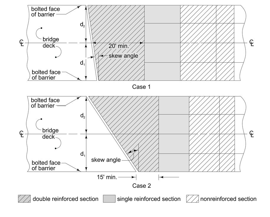
Figure 1: Case 1 and Case 2 bridge approach section layouts.
Widths d1 and d2 in Figure 1 are measured from the centerline to the bolting face of the barrier. Of the two, d1 is always taken to be located on the shorter side of the double reinforced bridge approach section.
Once the proper case to use for the double reinforced bridge approach dimensions has been determined, refer to Standard Road Plans SW-538, SW-539, DR-401, and DR-402 as well as the BR-200s for further information regarding double reinforced bridge approach sections and approach pavement. Indicate on Tabulation 112-6 whether the abutment is fixed (tied) or movable (untied). Also indicate the skew angle and side ahead (for example, 11° left ahead).

| Do not use single reinforced bridge approach sections on Primary Road System bridges. Use of double reinforced bridge approach sections on Secondary Road System bridges is encouraged. |
|---|
Details ‘D’ and ‘E’ on the last pages of Standard Road Plans BR-201, BR-202, BR-203, and BR-204 show the back of curb in relation to the guardrail mounting surface (bolting face) for typical bridge end posts. Details ‘F’ and ‘G’ on the last page of Standard Road Plan BR-205 show the back of curb in relation to the guardrail mounting surface for typical bridge end posts. These dimensions are important to ensure guardrail posts can be placed properly.
Examples 1 and 2 below to demonstrate how to determine which case is appropriate for determining double reinforced bridge approach section dimensions.
Back to topExample 1
The skew angle for the bridge shown in Figure 2 is 10°. This bridge will be a two lane bridge with 10’ shoulders. Determine which case is appropriate to establish double reinforced bridge approach dimensions.
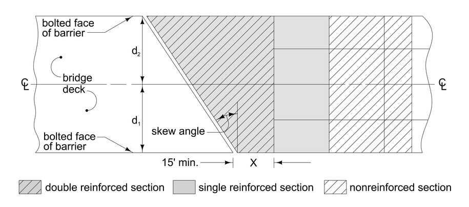
Figure 2: Bridge layout for examples.
First determine the width (W) to the centerline of the road:
\(d_1 + 10'' = 22'\)
Next, assume X = 15’.
Y = (22’)(tan10°) + 15’ = 18.88’ < 20’
However, Y must be at least 20’ so use Case 1.
Back to topExample 2
The skew angle for the two lane bridge shown in Figure 2 is 30°. Determine which case is appropriate to establish double reinforced bridge approach dimensions.
First determine the width (W) to the centerline of the road:
\(d_1 + 10'' = 18'\)
Next, assume X = 15’
Y = (18)(tan30°) + 15’ = 25.39’ > 20’
Y is greater than 20’, so use Case 2.
Back to top