
Content Information
On this page...
On-site Detours
On-site detours (also called runarounds) are used to bypass a work area for locations where a road closure isn’t desirable and a detour routed on existing roadways would be impractical. Typically, these are used on two lane roadways at spot locations such as a bridge replacement.
Back to topDesign Considerations
The design approach used for these roadways reflects their purpose: a short term deviation to minimize out-of-distance travel. As such, constructability and economy take precedence over providing the level of driver comfort and mobility desired of a long term facility. Design the alignment to:
Avoid interference with construction,
Provide design speed appropriate geometry to ensure safe operation, and
Minimize impacts to the adjacent land and environment, including the magnitude and cost of utility relocation.
Standard Road Plans TC-253, PV-418, and PV-428 are used with on-site detour designs. They are based on a 1000 foot radius, which is good for a 40 mph design speed.
The guidance that follows assumes summer use only operations. If the detour will or may be used over the winter, a much more conservative design will be required.
Specific elements of a detour design that should reflect the work zone environment and temporary nature of these facilities include:
Design Speed
An appropriate design speed for a rural detour is generally 40 mph. This is 5 mph higher than the signing and should be appropriate where congestion is not a concern. Physical and economic constraints may necessitate a design speed of less than 40 mph. The approval of the Project Engineer is required for a reduced design speed. If the design speed can be increased with little to no impact this should be considered, especially if there is a chance of creating a traffic backup with the detour. If the design speed is increased, the traffic control signing should be adjusted accordingly.
Horizontal Alignment
Design the horizontal alignment using the design speed.
Superelevation
Use Method 2 superelevation distribution for on-site detours with a design speed of 40 mph or less. An acceptable design can be developed using a single cross slope for length of the detour (see Figure 1) with the appropriate curvature allowed for that cross slope as negative superelevation.
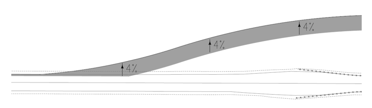
Figure 1: Pavement slope for an on-site detour. Method 2 distribution is appropriate for the driver to cross over crown lines and slopes at pavement edges at either end where the detour connects to the existing roadway.
If curvature sharper than that discussed above is required, transition cross slopes between curves using appropriate guidelines.
Minimum Radius
The use of minimum radii per Method 2 distribution is practical for a detour. Designers should select the appropriate negative superelevation rate of the cross slope for locations where appropriate.
Coordination with the Office of Bridges and Structures
Provide a tangent section across a stream if a temporary bridge is used to convey drainage.
The Office of Bridges and Structures provides the design of the bridge or drainage structure to designers.
Grade between the detour and existing roadway to drain the water away from the area. The Office of Bridge and Structures will need to design a temporary culvert to drain other areas.
Removal of temporary culvert pipes is incidental to the bid item for culvert pipe. The plans should specify in the Estimate Reference Information that, upon removal, these temporary culvert pipes become the property of the contractor and the contractor will be responsible for proper disposal.
Back to topVertical Alignment
Design vertical curves for the design speed. Refer to Section 2B-1 for guidance.
Back to topClear Zone
Provide work zone clear zone distance as described in Section 8A-2.
Back to topCross Sectional Elements
Use a two lane detour for traffic volumes of 3000 ADT. Typical cross sections for paved two lane detours will be a 28 foot pavement with 3:1 foreslopes (two 11 foot lanes and two 3 foot shoulders).
Use a one lane detour for traffic volumes less than 3000 ADT. Cross sections for paved one lane detours will be a 16 foot pavement with 3:1 foreslopes (one 12 foot lane and two 2 foot shoulders).
Refer to the Detour Paving typical for details.
Back to topPavement Cross Slope
The cross slope of the pavement surface may be held constant with the use of radii that meet Method 2 superelevation distribution.
Back to topPavement Cross Slope Breaks
The maximum cross slope break between the existing pavement edge and the detour connection is 5.0%.
Back to topPavement Design
Obtain the detour pavement design from the Pavement Design Engineer. Refer to Section 2304 of the Standard Specifications for further information about pavement options.
Back to topSight Distance
Decision sight distance to the approach of the runaround is desirable. Provide stopping sight distance through the work zone. Refer to Section 6D-1 for sight distance guidance.
Back to topTraffic Control
Refer to Standard Road Plan TC-253 and the MUTCD for traffic control guidance. Section 9C-3 has more information.
Advance signing and proper pavement markings are also necessities for the safe operation of a detour or temporary connection.
For one way, signalized operations, the maximum distance between stop bars is 1300 feet (see TC-253). A distance that exceeds 1300 feet will need non-standard signal timing.
Standard Road Plans
Standard Road Plans PV-418 and PV-428 detail the primary road to detour connection for a one lane and two lane run around. The use of these standards is appropriate for connecting a detour to a tangent section of roadway or within a curve that is not superelevated.
The design speed of the geometry for the standard road plans is 40 mph. Design the other curves on the detour alignment for 40 mph. Include transitions for changes in the cross slope.
Back to topExample using COGO
A two lane on site detour is required to redirect traffic around a work area. The road is a rural two lane with a posted speed of 55 mph. The detour will be designed to a 45 mph design speed using Table 1 of Section 2A-3.
Standard Road Plan PV-428 is used to make the connection between the existing roadway and the detour. This sets the beginning and ending locations and bearings of the detour alignment, see Figure 2.
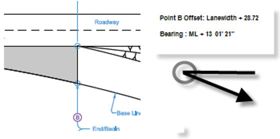
Figure 2: Detour alignment tie-in.
Maintaining a constant 4% cross slope as set by PV-428 is desirable. This allows reverse curves to be located adjacent to each other without providing special superelevation details or adding tangent between the curves.
The incomplete alignment algorithm within Geopak COGO can be used to define the detour geometry.
The commands below, included as a portion of an input file, produce the illustration in Figure 3.
$ MIDDLE BEAVER CREEK RUNAROUND
$ CHAIN DET1
$ POINT RANGE 10,000 - 10,050
$ DESIGN SPEED 45
$ CONNECT PER PV-428
LOCATE 10000 ON CHAIN ML030 STA 295+40
LOCATE 10001 ON CHAIN ML030 STA 295+40 OFFSET -40.72
LOCATE 10002 ON CHAIN ML030 STA 305+00 OFFSET 0
LOCATE 10003 ON CHAIN ML030 STA 305+00 OFFSET -40.72
ALI DET1 INC
POT 10001 TD 10000 TO 10001 + 76 58 39 STA 1295+40 $ 90 - PV-428 DEFLECTION
CUR 10001 TL 0 R 1000 M DEF ?
CUR 10002 TL 0 R 1250 P DEF ?
CUR 10003 TL 0 R 1000 M DEF ?
POT 10003 TL 0 TD 10002 TO 10003 + 103 01 21
END ALI DET1 DES
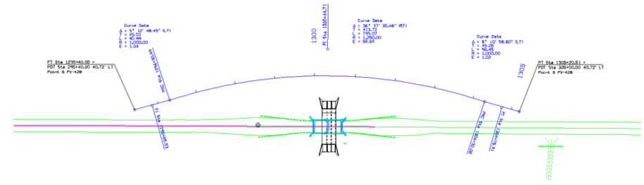
Figure 3: Median crossover geometry for example problem using COGO.
Similarly, the beginning and end of the profile is set at the connection points from the use of the Standard Road Plan.
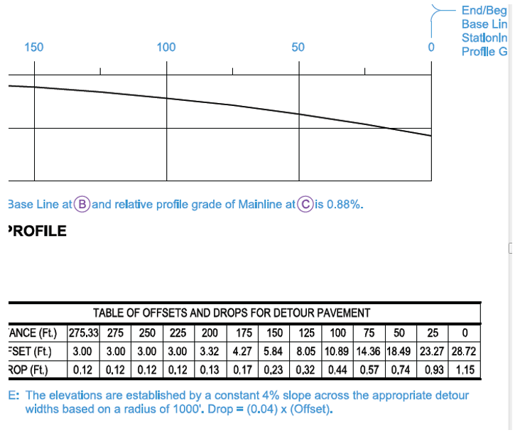
The commands below were used to establish the profile.
$ PROFILE DESIGN ASSUMES 0.24' DROP TO EOP
ELEVATION PROFILE ML030_E 295+40.00
ELEVATION PROFILE ML030_E 305+00.00
STO PRO DET1_P
VPI 10 S 1295+40 E 1011.24
VPI 20 S 1296+40 E 1010.28 L 200
VPI 30 S 1304+00 E 1011.47 L 200
VPI 40 S 1305+20.51 E 1011.96
END PRO DET1_P
PRI PRO DET1_P
Back to top