Content Information
On this page...
This section discusses drainage structures used for capturing stormwater runoff from bridges. These structures are commonly referred to as bridge end drains. If water flows away from a bridge corner, a bridge end drain is needed.
Back to topChoosing a Bridge End Drain
Runoff from bridges can be captured with intakes or flumes. Typically, flumes are used in rural areas, whereas intakes are used in urban areas or in high fill situations. However, the best option to use depends on site characteristics as well as maintenance and safety concerns.
Intakes
In urban areas with curb and gutter, use an SW series Standard Road Plan storm sewer intake. Refer to Section 4A-4 for more on urban drainage design.
In other areas where high fills, high flows, and/or erosive soils are present, use an intake bridge end drain (Standard Road Plans SW-538 and SW-539).
Flumes
If the area will be mowed regularly or if traversability of errant vehicles is a concern, use a scour protection flume (Standard Road Plan DR-401).
If mowing and/or traversability are not a concern, use a rock flume (Standard Road Plan DR-402).
Contact the Roadside Development Section in the Design Bureau for additional information.
Back to topLocating Bridge End Drains
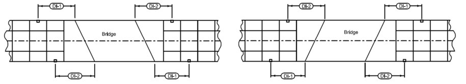
Bridge end drains should not be located immediately adjacent to the bridge end. Paved shoulders are often needed to convey drainage away from the bridge to the bridge end drain. Distances from each bridge corner to the center of a proposed bridge end drain (DI-1 and DI-2) are shown in Figure 1. DI distances are measured from the center of the bolt hole pattern used to attach guardrail to the bridge.
A curb is necessary to carry the runoff from the bridge to the bridge end drain. Therefore, the reinforced bridge approach section, as well as paved shoulders, must include a curb. Typically, a 4 inch sloped curb is used. For flumes, the curb terminates at the bridge end drain. For intake bridge end drains, the curb is carried to a point 5 feet beyond the centerline of the intake. Details of this termination are shown on each drainage structure’s respective standard road plan.
When guardrail will be installed at a bridge end, the design of the guardrail may influence the location of a proposed drainage structure, as well as the shape of the shoulder. Therefore, for ease of design and construction, maintain a tangent guardrail alignment (no flare) until it reaches a point beyond the bridge end drain. Refer to Chapter 8 for additional information related to guardrail design.
Flumes (DR-401 and DR-402)
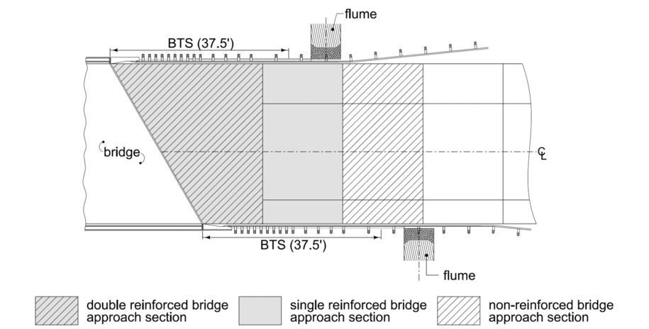
Locate flumes beyond the BTS and where guardrail posts are spaced 6’-3” apart to minimize the number of posts in the flume, as shown in Figure 2.
Intake Bridge End Drains (SW-538 and SW-539).
Do not locate intake bridge end drains in the double reinforced bridge approach section. Instead, locate them so:
- They are located between guardrail posts that are spaced 6’-3” apart to eliminate the risk of a guardrail post penetrating the outlet pipe,
- The center is at least 6 feet from the nearest joint, and
- The curb drop occurs beyond the BTS.
The following example problems demonstrate the process for locating intake bridge end drains.
Example Problem 4C-2_1, Determining Intake Bridge End Drain Location
Example Problem 4C-2_2, Determining Intake Bridge End Drain Location
In the case of narrow bridge shoulders (4 feet or less), locating an SW-538 or SW-539 intake bridge end drain at the proposed location may not be possible. Consider using a flume or drawing up the bridge/guardrail situation to locate the drain further from the bridge in an area where the shoulder width can be made greater than 4 feet.
Back to topHydraulic Evaluation of Intake Bridge End Drains
Grate Capacity
After locating an intake bridge end drain, compute storm runoff Q in cfs for the design storm (refer to Section 4A-5) and determine grate intercept capacity. When using an SW-538 or SW-539, grate intercept capacity Qi is determined using the equation:
\(Q_i = E Q\) (Equation 4C-2_1)
where:
\(Q_i\) = Intercepted flow, \(ft^3/s\).
E = Intake efficiency.
Q = Design gutter flow, \(ft^3/s\).
Bypass flow is flow bypassing an intake. The general equation relating bypass to intercepted flow is:
\(Q_b = Q - Q_i\) (Equation 4C-2_2)
where:
\(Q_b\) = Bypass flow, \(ft^3/s\).
Qi = Intercepted flow, \(ft^3/s\).
Q = Design gutter flow, \(ft^3/s\).
Efficiency
Efficiency is the percent of total flow that the intake will intercept under a given set of conditions. The efficiency changes with changes in pavement cross slope, longitudinal slope, and roughness, as well as total gutter flow.
The interception capacity of an intake bridge end drain depends on:
- Flow in the gutter section.
Flow velocity in the gutter.
The efficiency for intake bridge end drains is determined by the following equation:
\(E = R_f E_0 + R_s (1 - E_0)\) (Equation 4C-2_3)
where:
\(E\) = Efficiency.
\(E_o\)= Frontal flow to total gutter flow ratio.
\(R_f\)= Frontal flow interception.
\(R_s\)= Side flow interception.
Frontal Flow to Total Flow Ratio
The ratio of frontal flow to total gutter flow is determined using the following equation:
\(E_{o} = 1 - \left(1 - \frac{W}{T}\right)^{2.67}\) (Equation 4C-2_4)
where:
\(E_o\) = Ratio of frontal flow to total gutter flow, (\(Q_w/Q\)).
W = Width of grate, ft. Use 1.90 ft, the width of the grate used with the SW-538 and SW-539.
T = Total spread, ft.
Frontal Flow Interception
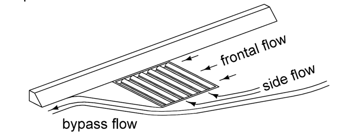
As shown in Figure 3, frontal flow is the portion of the flow that passes over the upstream side of a grate. The ratio of frontal flow intercepted to total frontal flow, Rf, is determined using the following equation:
\(R_f = 1 - K_f (V - V_o)\) (Equation 4C-2_5)
where:
\(K_f\)= Empirical coefficient, 0.09.
\(V\)= Velocity of flow in the gutter, ft/s.
\(V_o\)= Gutter velocity where splash-over first occurs, ft/s. Use 5.6 ft/s, the splash-over velocity for the grate used with the SW-538 and SW-539.
Note: \(R_f\) cannot be greater than 1.00. If \(V\) ≤ \(V_o\), then all flow is intercepted. If \(V_o\) < \(V\), then only a portion of the flow is intercepted.
Velocity of flow in the gutter (V) is determined as follows:
\(V = \frac{2Q}{T^{2} S_x}\) (Equation 4C-2_6)
where:
\(Q\)= Flow in gutter, \(ft^3/s\).
\(T\)= Spread, ft.
\(S_x\)= Cross slope of pavement, ft/ft.
Side Flow Interception
As shown in Figure 3, side flow interception is flow that is intercepted along the side of a grate inlet. The ratio of side flow intercepted to total side flow, Rs, is determined using the following equation:
\(R_s = \frac{1}{1 + \frac{K_s V^{1.8}}{S_x L^{2.3}}}\) (Equation 4C-2_7)
where:
\(K_s\)= Empirical Coefficient, 0.15.
\(V\)= Velocity of flow in the gutter, ft/s.
\(S_x\)= Cross slope, ft/ft.
L = Length of grate, ft. Use 1.90 ft, the length of the grate used with the SW-538 and SW-539.
Once \(R_f\), \(E_o\), and \(R_s\) are determined, solve for E using Equation 4C-2_3 and then solve for \(Q_i\) and \(Q_b\) using Equations 4C-2_1 and 4C-2_2 as illustrated in the following example.
Example Problem 4C-2_3, Evaluate an Intake Bridge End Drain
The allowable bypass should not exceed 10%. If bypass exceeds 10%, a second intake is needed downstream of the first intake to reduce the amount of bypass. The second intake should also be spaced according to the rules defined earlier. The second intake may be joined to a common storm sewer outlet.
Back to top
Example Problem 4C-2_1, Determining Intake Bridge End Drain Location
Determine the intake bridge end drain location for the following situation.
Given:
Two 12 foot lanes
Shoulder widths are 6' and 10'
Skew angle is \(30^0\)
Determine the inlet location.
Solution:
Intake location is a function of various bridge characteristics, the bridge approach section, and the placement of the guardrail. The best way to place the intake is to draw the bridge situation plan, locate the joints in the approach section, and determine the position of guardrail and guardrail posts.
Standard Road Plan SW-538 shows the point from which DI1 and DI2 are measured when using BA-202. Standard Road Plan BA-250 shows the location station to be used for a guardrail installation at a bridge end when using BA-202.
Determine the proper reinforced bridge approach section dimensions, see Section 7D-1. This case will be a Case 2 situation (see Example 2 in Section 7D-1).
Determine d1 and d2 for the bridge approach. Of the two, d1 is always the shoulder width on the shorter side of the double reinforced bridge approach section. For this example d1 = 6' and d2 = 10'.
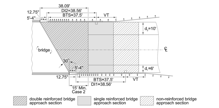
In Figure 1 on the d1 side, the first joint is located at 15'-0" – 5'-4" = 9'-8" from the bolt hole location shown in BA-202. The next two joints are located at 29'-8" and 49'-8" respectively.
DI1= 12¾ in. + 25 ft + 12.50 ft = 38.56 ft from the bolt hole location, which places the center more than 6 ft. from the nearest joint and between two guardrail posts, see Figure 1. Additionally, the curb drop will occur beyond the BTS.
In Figure 1 on the d2 side, the first joint is located at 38.09' – 5'-4" = 32.76 ft from the bolt hole location. The next two joints are located at 52.76 ft and 72.76 ft respectively.
DI2 = 12¾ in. + 25 ft + 12.50 ft = 38.56 ft from the bolt hole location, which places the center more than 6 ft from the nearest joint and between two guardrail posts, see Figure 1. Additionally, the curb drop will occur beyond the BTS.
Discussion:
This example gives a minimum requirement for intake location. Intakes can be moved a greater distance from the location station, if desired, but the designer should then verify that:
The intake is located approximately in the middle of two guardrail posts.
The center of the intake is at a 6 foot minimum distance from the nearest joint and beyond the reinforced bridge approach section, and the curb drop occurs beyond the BTS.
If condition 1 or 2 is not met, the designer should extend the guardrail by 12.5 foot increments in the variable tangent section of the guardrail layout, then check the location of the intake at 6.25 foot increments until it meets the requirements.
Back to top
Example Problem 4C-2_2, Determining Intake Bridge End Drain Location
Determine the intake bridge end drain location for the following situation.
Given:
Two 12 foot lanes
Shoulder widths are 10' and 10'
Skew angle is \(10^0\)
Determine the inlet location.
Solution:
Intake location is a function of various bridge characteristics, the bridge approach section, and the placement of the guardrail. The best way to place the intake is to draw the bridge situation plan, locate the joints in the approach section, and determine the position of guardrail and guardrail posts.
Standard Road Plan SW-538 shows the point from which DI1 and DI2 are measured when using BA-202. Standard Road Plan BA-250 shows the location station to be used for a guardrail installation at a bridge end when using BA-202.
Determine the proper reinforced bridge approach section dimensions, see Section 7D-1. This case will be a Case 1 situation (see Example 1 in Section 7D-1).
Determine d1 and d2 for the bridge approach. Of the two, d1 is always the shoulder width on the shorter side of the double reinforced bridge approach section. For this example d1 = 10' and d2 = 10'.

In Figure 1 on the d1 side, the first joint is located at 16.12' – 5'-4" = 10.79' from the bolt hole location shown in BA-202. The next two joints are located at 30.79' and 50.79' respectively.
DI1 = 12¾ in. + 25 ft + 12.50 ft = 38.56 ft from the bolt hole location, which places the center more than 6 ft from the nearest joint and between two guardrail posts, see Figure 1. Additionally, the curb drop will occur beyond the BTS.
In Figure 1 on the d2 side, the first joint is located at 23.88' – 5'-4" = 18.55 ft from the bolt hole location. The next two joints are located at 38.55' and 58.55' respectively.
DI2 = 12¾ in. + 25 ft + 6.25 = 32.31 ft from the bolt hole location, which places the center more than 6 ft from the nearest joint and between two guardrail posts, see Figure 1. Additionally, the curb drop will occur beyond the BTS.
Discussion:
This example gives the minimum requirement for intake location. Intakes can be moved a greater distance from the location station, if desired, but the designer should then verify that:
The intake is located approximately in the middle of two guardrail posts.
The center of the intake is at a 6 foot minimum distance from the nearest joint and beyond the reinforced bridge approach section, and the curb drop occurs beyond the BTS.
If condition 1 or 2 is not met, the designer should extend the guardrail by 12.5 foot increments in the variable tangent section of the guardrail layout, then check the location of the intake at 6.25 foot increments until it meets the requirements.
Back to top
Example Problem 4C-2_3, Evaluate an Intake Bridge End Drain
Determine intercepted and bypass flows by calculating the efficiency of an intake bridge end drain.
Given:
Cross slope: \(S_x\) = 0.03 ft/ft.
Manning’s coefficient for new pavement: n = 0.016.
Total flow rate: Q = 1.6 \(ft^3/s\).
Longitudinal slope: SL = 0.02 \(ft/ft\).
Allowable spread = 6 ft.
Solution:
Use Equation 4A-6_4 from Section 4A-6 to find the gutter spread (T) directly upstream of the intake:
\(T = \left[ \frac{nQ}{K_u S_x^{1.67} \sqrt{S_L}} \right]^{-0.375} = \left[ \frac{0.016 \times 1.6}{0.56 \times 0.03^{1.67} \times \sqrt{0.02}} \right]^{-0.375} = 5.89\ \text{ft}\)
Gutter spread is less than allowable spread, so spread is acceptable.
Use Equation 4C-2_4 to calculate the grate frontal flow to total gutter flow (\(E_o\)):
\(E_o = \left[ 1 - \left( 1 - \frac{W}{T} \right)^{2.67} \right] = \left[ 1 - \left( 1 - \frac{1.90}{5.89} \right)^{2.67} \right] = 0.647\ \text{or}\ 65\%\)
Use Equation 4C-2_6 to calculate the average gutter velocity (V):
\(V = \frac{2Q}{T^{2} S_x} = \frac{2 \times 1.6}{5.89^{2} \times 0.03} = 3.08\ \text{ft/s}\)
Use Equation 4C-8_2 to calculate the frontal flow interception (\(R_f\)):
\(R_f = 1 - K_f (V - V_o) = 1 - 0.09(3.08 - 5.6) = 1.23 > 1.0\)
Since the frontal flow interception (\(R_f\))is greater than 1.0, use \(R_f\) = 1.0
Use Equation 4C-2_7 to calculate the side flow interception (\(R_s\)):
\(R_s = \frac{1}{1 + \frac{K_s V^{1.8}}{S_x L^{2.3}}} = \frac{1}{1 + \frac{0.15 \times 3.08^{1.8}}{0.03 \times 1.90^{2.3}}} = 0.104\ \text{or}\ 10\%\)
Use Equation 4C-2_3 to calculate the efficiency (E):
\(E = R_e E_o + R_s(1 - E_o) = (1 \times 0.647) + 0.104(1 - 0.647) = 0.684\ \text{or}\ 68\%\)
This is less than 90%, so an additional intake is required downstream.
Use Equation 4A-8_1 to calculate the intercepted flow (\(Q_i\)):
\(Q_i = E Q = 0.68 \times 1.6 = 1.09\ \text{ft}^3/\text{s}\)
Use Equation 4A-8_2 to calculate the bypass flow (\(Q_b\)):
\(Q_i = E Q = 0.68 \times 1.6 = 1.09\ \text{ft}^3/\text{s}\)
Discussion:
Efficiency is less than 90%, so the designer will need to place a second intake downstream. This intake should also be placed between guardrail posts with the center a minimum of 6 feet (1.5 meters) from the nearest joint. This intake will also need to be evaluated to ensure that bypass does not exceed 10% of the gutter flow coming from the bridge. The second intake may be joined to a common storm sewer outlet.
Back to top