Content Information
On this page...
This section describes how to joint a cul-de-sac by following the guidelines outlined in Section 7A-2. The process is illustrated through an example of a city street that is terminated with a cul-de-sac. For this example, assume the pavement thickness is 7 inches.
Back to topStep 1: Place Longitudinal Joints
The longitudinal joints running down the city street should be extended into the cul-de-sac. The remaining longitudinal joints in the cul-de-sac should be placed roughly a lane width apart—somewhere in the range of 10 to 16 feet is acceptable (see Figure 1).
Standard Road Plan PV-101 and Table 2 in Section 7A-2 indicate that a BT-1 or L-1 is an appropriate longitudinal joint type to use since the pavement thickness is less than 8 inches.
Back to topStep 2: Place Transverse Joints
The next step is to place transverse joints. The maximum spacing for transverse joints is 17 feet and the minimum spacing is 12 feet. Therefore, the joints within the cul-de-sac should be spaced within this range (see Figure 1).
Standard Road Plan PV-101 and Table 1 in Section 7A-2 indicate that a C joint is the appropriate transverse joint type to use since the pavement thickness is less than 8 inches.
Back to topStep 3: Extend Joints through the Free Edge of the Pavement
When extending the previously placed joints through the free edge of the pavement, keep in mind that the acute angle between the joint and the pavement edge (and between the joint and other joints) must be greater than or equal to 70 degrees. Also, all joints should be at least two feet long. Details A, B, and C in Figure 2 illustrate how this can be accomplished.
Detail A shows a transverse joint that is extended through the free edge of the pavement unaltered. This is acceptable because all angles between the transverse joint and the longitudinal joints and between the transverse joint and the free edge of the pavement are greater than 70 degrees.
Detail B uses a dashed line to show the original position of a transverse joint which creates an angle with the free edge of the pavement less than 70 degrees. This joint should be skewed to make it perpendicular to the free edge of the pavement, as shown by the solid line.
Detail C illustrates a situation where skewing the joint to make it perpendicular to the free edge of the pavement would cause the angle between the joint and a longitudinal joint to be less than 70 degrees (shown by the dashed line). When this situation occurs, the joint is extended a minimum of two feet beyond the longitudinal joint, and then skewed to make it perpendicular to the free edge of the pavement. Both segments of the joint should be at least two feet long.
After all joints are placed, the layout should be checked to ensure that all joint spacings and angles are acceptable.
Back to topStep 4: Label Joints
The completed jointing layout for the cul-de-sac is shown in Figure 2. As stated on Standard Road Plan PV-101, the L-1 and BT-1 joints may be used interchangeably, at the contractor’s discretion, depending on the paving sequence. Therefore, the designer may identify the longitudinal joints as either L-1 or BT-1 on the jointing layout.
Because the majority of the joints are either C joints or BT-1 or L-1 joints, not every joint on the jointing layout needs to be identified. A note on the plan describing the transverse joints as C and longitudinal joints as L-1 or BT-1 except as noted otherwise is sufficient, provided that a few key joints on the diagram are identified. Whenever a series of joints changes to a different type of joint, the joint at the location of the change is identified. Any joint that may be a source of confusion should also be labeled.
Joint lengths are also shown on the jointing layout, normally rounded to the nearest foot. Similar to labeling joint types, not every length needs to be indicated. However, any length that cannot be inferred from the diagram should be labeled.
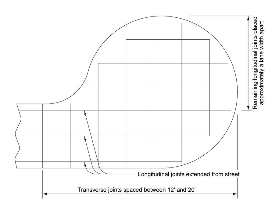
Figure 1: Placement of longitudinal and transverse joints.
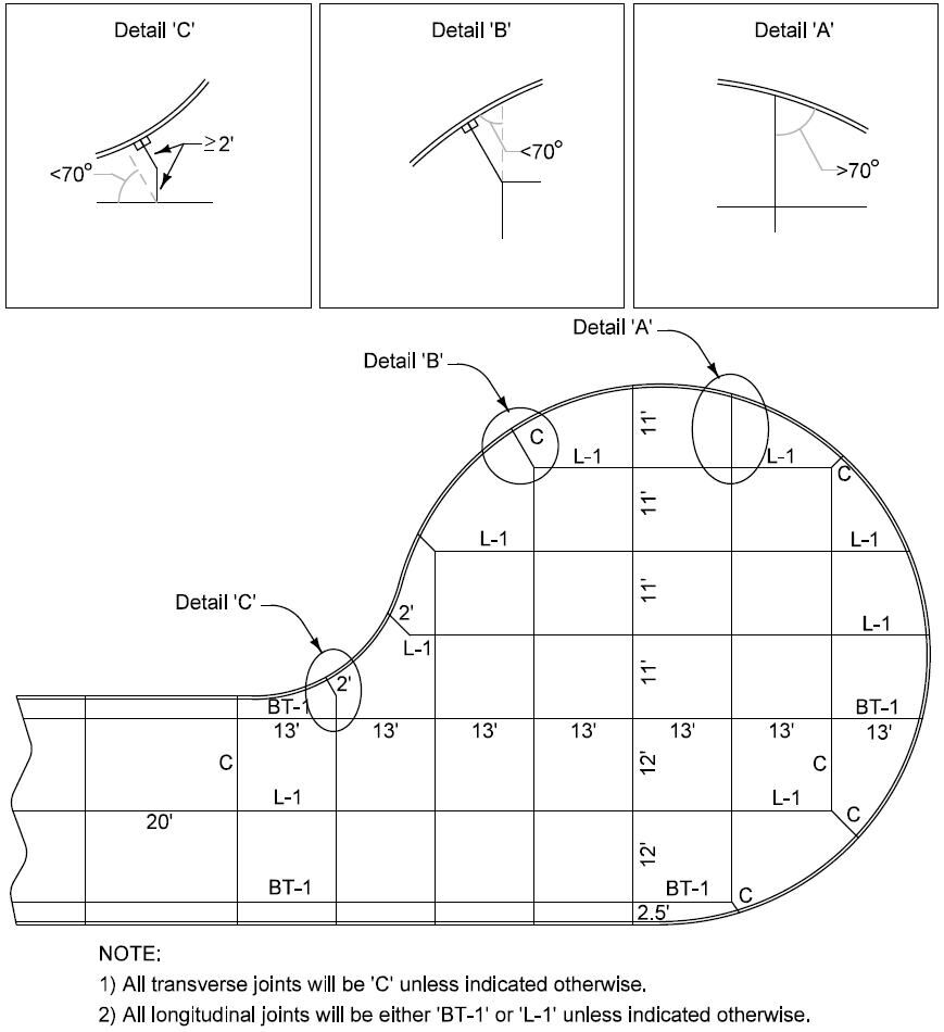
Figure 2: Final jointing layout.
Back to top