Content Information
On this page...
High tension cable guardrail is a flexible barrier system that consists of tensioned steel cables held at varying heights by weak steel posts. The posts are installed in sleeves within concrete foundations, which eases post replacement. Tension in the cables is maintained by anchors at each end of the installation.
High tension cable guardrail is most often used to reduce cross-median crashes and is also the preferred method of shielding median bridge piers. It can also be used to protect other types of objects, as long as adequate distance is provided from the face of the object to the installation line to account for deflection of the cable system.
For installations on level ground, a minimum of 10 feet (14 feet preferred) should be provided from the face of the object to the installation line of the cable. If a minimum of 10 feet isn’t available, contact the Roadside Safety Engineer.
High tension cable guardrail can be placed on slopes provided they are 4:1 or flatter. If it is being placed on a 6:1 or steeper slope to protect an object, it should be placed a minimum of 14 feet from the face of the object to provide a margin of safety to account for the slope. If a minimum of 14 feet isn’t available, contact the Roadside Safety Engineer.
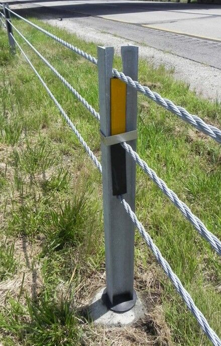
High tension cable guardrail example

| High tension cable guardrail should not be placed behind a curb. |
|---|
Placing high tension cable guardrail on slopes involves some limitations:
On slopes 6:1 or flatter, the high tension cable guardrail can be located any distance from the foreslope breakover, see Figure 1. However, it cannot be placed any closer than 8 feet from the breakover at the bottom of a ditch, see Figure 1.
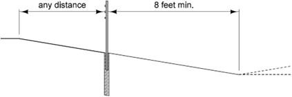
Figure 1: High tension cable guardrail placed on slopes 6:1 or flatter.
On slopes of 4:1 up to (but less than) 6:1, the high tension cable guardrail must be located no more than 4 feet, or no less than 20 feet, from the foreslope breakover, see Figure 2. It should be placed no closer than 8 feet from the breakover at the bottom of a ditch, see Figure 2.
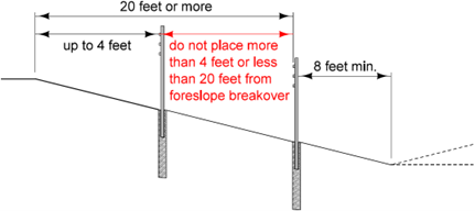
Figure 2: High tension cable guardrail placed on slopes 4:1 to less than 6:1.
A common situation that arises is the need to place high tension cable adjacent to steep slopes (to as steep as 2:1). Manufacturers of the high tension cable guardrail systems approved by the Iowa DOT recommend a minimum of 1 foot (2 feet preferred) between the back of post and the breakover, see Figure 3.
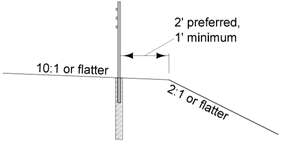
Figure 3: High tension cable guardrail placed adjacent to steep slopes.
If high tension cable guardrail needs to be flared, it should be flared at a rate of 50:1.
Back to topDesign Process for Protecting Roadside Objects (One Way Traffic)
The process for laying out the BA-351 high tension cable guardrail for one way traffic involves five steps:
1. Select the offset from the edge of pavement (DO).
Normally, the high tension cable installation line is placed 12 feet (14 feet for Interstates) in front of the object. This offset can be greater, but it should not be less than 10 feet (12 feet for Interstates). If the object is within a narrow median that does not accommodate this design, or if the object is located close enough to the edge of traveled way that the installation line encroaches on the shoulder, consult the Roadside Safety Engineer for assistance. For placement on Interstates, designers should check to ensure deflection from a backside cross median impact won’t intrude on the traveled lanes.
2. Determine the vehicle departure path.
Determine the vehicle departure path as described in Section 8B-6.
3. Calculate the approach cable length (CA).
Measure the distance between the approach end of the object and the point where the installation line crosses the departure path. Round this measurement up to the next 10 foot increment. Use this value as the approach cable length.
4. Determine the object cable length (CO).
Measure the length of the object along centerline. Round this measurement up to the next 10 foot increment. Use this value as the object cable length.
5. Calculate the protection length.
Add the approach cable length to the object cable length to determine the protection length (Protection Length = CA + CO). This is the bid quantity that will be entered in the plans.
The example below demonstrates.
Do is 16 feet.
Clear zone is 34 feet.
Runout length is 360 feet.
The length of the object is 16 feet measured along the centerline. The back of the object is beyond the clear zone, so the object is protected to the clear zone.
The figure below shows the set up:
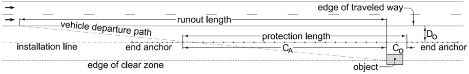
The vehicle departure path crosses the installation line 191 feet upstream of the object. Rounding this up to the next 10 foot increment gives a CA of 200 feet.
The length of the object (16 feet) is rounded up to the next 10 foot increment, so CO is 20 feet.
The protection length is CA + CO = 200 + 20 = 220 feet.
Back to topDesign Process for Protecting Roadside Objects (Two Way Traffic)
The process for laying out the BA-351 high tension cable guardrail for two way traffic involves six steps:
1. Select the offset from the edge of pavement (\(D_O\)).
The guidance given for one way traffic applies.
2. Determine the vehicle departure path for the adjacent and opposing traffic.
Determine the vehicle departure paths as described in Section 8B-6.
3. Calculate the approach cable length (\(C_A\)).
Measure the distance between the approach end of the object and the point where the installation line crosses the departure path for the adjacent traffic. Round this measurement up to the next 10 foot increment. Use this value as the approach cable length.
4. Determine the object cable length (\(C_O\)).
Measure the length of the object along centerline. Round this measurement up to the next 10 foot increment. Use this value as the object cable length.
5. Calculate the trailing cable length (\(C_T\)).
Measure the distance between the trailing end of the object and the point where the installation line crosses the departure path for the opposing traffic. Round this measurement up to the next 10 foot increment. Use this value as the trailing cable length.
6. Calculate the protection length.
Add the approach cable length, the object cable length, and the trailing cable length to determine the protection length (Protection Length = \(C_A\) +\(C_O\) + \(C_T\)). This is the bid quantity that will be entered in the plans.
The example below demonstrates.
\(D_O\) is 8 feet.
Clear zone is 30 feet.
Runout length is 210 feet.
The length of the object is 16 feet measured along the centerline. The back of the object is at the clear zone.
The figure below shows the set up:
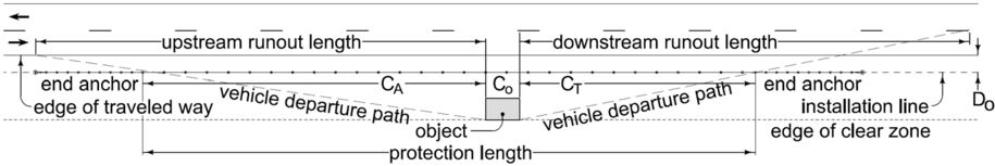
The vehicle departure path crosses the installation line 154 feet upstream of the object. Rounding this up to the next 10 foot increment gives a CA of 160 feet. The vehicle departure path for opposing traffic crosses the installation line 110 feet downstream of the object. This gives a CT of 110 feet.
The length of the object is 16 feet, so Co is 20 feet.
The protection length is \(C_A\) +\(C_O\) + \(C_T\) = 160 + 20 + 110 = 290 feet.
Back to topEnd Anchors
Every installation must have end anchors. These are added at each end of the installation, but the lengths of the anchors are not included in the protection length. Anchor lengths among the approved manufacturers vary from approximately 30 feet to 50 feet. Since it is unknown which system will be installed, consider 50 feet as the minimum length needed to install any end anchor.
Although end anchors can be placed up to a mile or more apart, this is undesirable since very long runs of cable are more difficult to keep tensioned and will have a higher deflection. Long runs also increase exposure if there is damage to the run resulting in the cable losing tension. Runs should be kept to less than 3000 feet of cable. If a run exceeds 3,000 feet, split it into two shorter runs.
Back to topHigh Tension Cable Guardrail in Curves
For High Tension Cable Guardrail installed in a curve with a radius of less than 650 feet, contact the Roadside Safety Engineer. Minimum curve radius allowed varies from manufacturer to manufacturer.
Back to topSpare Parts Kits
Contact the District to determine whether spare parts kits are desired for the proposed installation. The local maintenance garage may already have sufficient inventory on hand for repairs.
Back to topPlan Preparation
For most projects, showing high tension cable guardrail installations in the plans should be very straightforward.
Reference BA-351 and EW-302 (for grading in the median, if applicable).
Show the installation locations on the plan & profile sheets. Use the HTCableRail line style to draw installations for plan sheets. For more complicated situations, individual detail sheets may be necessary. Contact the Methods Section for guidance.
Use tabulation 108-9A to identify the specifics of the installation.
The payment length for high tension cable guardrail equals the protection length. The lengths of end anchors are not measured for payment; instead, they are counted as “each” items.
Associated bid items are:
2505-6000111 HIGH TENSION CABLE GUARDRAIL
2505-6000121 HIGH TENSION CABLE GUARDRAIL, END ANCHOR
2505-6000131 HIGH TENSION CABLE GUARDRAIL, SPARE PARTS KIT