
Content Information
On this page...
General
Light-weight temporary traffic control devices are not designed to protect workers from errant vehicles, nor do they protect vehicles from hazards often encountered in work zones. Positive protection systems provide greater physical protection for drivers and workers. These systems contain and/or redirect vehicles, thereby preventing intrusion into the workspace. Common positive protection systems contained in this section are Temporary Barrier Rail (TBR), energy absorbing or redirective end treatments, and shadow vehicles with energy-absorbing Truck or Trailer Mounted Attenuators (TMA).
For reference in this section, the term High Speed means operating speeds of 45 mph and greater. In Temporary Traffic Control (TTC) zones the Clear Zone is defined as 15 feet for high-speed roadways. For lower operating speeds the actual clear zone is often less and must be determined by roadway usage, operating speeds, and engineering judgment.
Use of Positive Protection
Positive protection use is outlined in §630.1108(a) of 23 CFR 630 Subpart K. Use of positive protection should be based on engineering judgment. If used improperly, a positive protection system can be hazardous for roadway users. A positive protection system should only be used when the severity of hitting it is less than the severity of impacting the hazard it is designed to protect. Each positive protection system must be carefully analyzed to ensure its use is appropriate for the specific situation. If possible, the hazard should be eliminated or moved beyond the clear zone.Consider the following mitigations before using positive protection:
- Reroute traffic and close the road,
- Use an on-site detour to offset traffic at least 15 feet from the work area,
- Limit the depth of excavations during non-working hours,
- Provide additional buffer between traffic and work activity.
Positive protection shall be used in work locations that provide workers no means of escape from an errant vehicle, unless an engineering study determines otherwise. This includes:
- Bridge deck overlays/reconstruction.
- Bridge rail construction/retrofit.
- Bridge inspections
- Work in tunnels or under a bridge
- Work next to permanent median barrier.
- When workers use lifts or buckets to perform overhead work
Common situations where positive protection may be warranted include:
- Work operations that place workers close to open lanes of traffic for more than two weeks.
- Roadside hazards left in place overnight or longer such as:
- Drop-offs on structures.
- Drop-offs or excavations near the traveled way (refer to Section 9C-2).
- Excavations for bridge piers.
- Fixed objects that cannot be easily removed, including temporary supports for structures.
- Work zones in place for one or more construction seasons with high traffic volumes and high operating speeds.
- Separation of two-way traffic in freeway work zones.
- To protect pedestrians in work zones.
Temporary Barrier Rail
Temporary Barrier Rail (TBR) is a safety device designed to prevent errant vehicles from penetrating into areas behind the barrier. A TBR installation consists of individual sections of TBR connected end-to-end. Its primary purposes are:
protection of drivers from obstacles in the work area,
protection of workers from vehicles leaving the traveled way, and
separation of high speed, multilane traffic flowing in opposite directions.
On complex projects where traffic must be realigned temporarily to accommodate work zone activity, it is often necessary to use temporary barrier for the reasons stated above. The designer must remember that temporary barriers should not be used as channelizing devices. The barrier is usually a last defense to keep traffic out of dangerous areas. Any traffic shifts must occur using crash-worthy channelizing devices, located well away from rigid temporary barriers. Regardless of the different types and abilities of drivers using the roadway, the designer must always strive to create a forgiving environment that allows for driver mistakes. When traffic is forced to make a shift adjacent to a rigid barrier, there is little room for driver error. Refer to Chapter 9C-X for more information on proper design techniques for staging complex projects.
Iowa DOT uses two types of TBR: concrete (BA-401) and steel (560-7). Concrete TBR is mostly used on roadway projects; however, it is also used on many bridge projects where lane width is not an issue.
Steel TBR is used almost exclusively on bridge projects where a narrow-width barrier is required. Contact the Roadside Safety Engineer prior to using steel TBR.
There are also other proprietary, crash-worthy barrier systems available from various suppliers. These systems each have differing performance characteristics, which must be considered prior to use on a project. These barrier systems should be considered for special circumstances such as:
- narrow width considerations,
- ease of installation and removal, and
- frequent relocation to handle directional peak hour traffic.
Although these systems will likely be more expensive than traditional barriers used in Iowa, their use may offset the cost by providing other benefits for safety and mobility.
Back to topLane Width
A TBR installation must be designed to provide adequate lane width for vehicles to travel through the work zone, yet at the same time provide sufficient space for construction activity. Sometimes compromises must be made to achieve acceptable results.
While it is desirable to maintain full width shoulders adjacent to a barrier, it is usually not practical. Strive to provide at least a 2 foot shy distance from the barrier.
For barrier that is to be left in place over winter, the distance is increased to 4 feet to allow for snow removal operations. When 4 feet is not practical, a 3-foot offset can be used. The final configuration should be determined after consultation with district maintenance staff.
The further the barrier can be placed from the traffic lane, the less likely it will be hit by vehicles. However, barrier offsets between 4 and 8 feet can cause operational problems when motorists attempt to use the narrow shoulder in an emergency. There is not enough room for the vehicle to safely vacate the lane. This results in reduced capacity when other motorists change lanes to avoid the vehicle that is still partially in the lane. It also increases the likelihood of a crash.
Multilane Traffic in a “chute”
Due to staging it is often it is necessary to place traffic between two lines of barrier, commonly referred to as a chute. Crashes that occur in the chute can lead to additional congestion. It is important to design the chute properly to mitigate operational problems due to a crash.
On multilane roadways the minimum width between barriers should be 30’ for 2-lane freeways or expressways. This dimension provides room for two 12-foot lanes and 3’ shoulders on each side. A 30’ width also helps to maintain the roadway speed and traffic capacity.
Cross sections less than 30’ for distances more than 1000’ should be avoided since this will result in reduced traffic capacity and increase the likelihood of crashes. A reduced regulatory speed limit should be considered.
A minimum width of 26’ is allowed for short lengths (up to 1000’). Due to the narrow width, an advisory speed or a reduced regulatory speed limit is warranted’.
Single lane situations (freeways and primary)
Maintain a minimum width of 15 feet 6 inches between TBR and bridge rail or other barriers whenever possible. This provides sufficient clearance for legal-width loads and a 1 foot cushion. Loads wider than 13 feet 5 inches require a special permit. Refer to Oversized Loads in Iowa Work Zones for further guidance regarding oversized loads and treatments. See the Iowa Truck Information Guide for more information on permitting requirements. (Truck Guide)

| Whenever a 15 foot 6 inch clearance cannot be provided, special signing must be placed in advance of the work zone. Notify the Work Zone Design Engineer and include Standard Road Plans TC-81 and SI-881 or SI-882, as appropriate, in the project |
|---|
|
| If a TBR installation results in a lane width less than 10 feet 6 inches, contact the Work Zone Design Engineer for a TBR design review. |
|---|
Access to the Work Area
An important consideration of any TBR installation is the impact it has on the flow of construction vehicles. Provide an entrance to the work area that is wide enough to allow passage of various types of construction vehicles that will be present on the project. However, to discourage the general public from inadvertently entering the work area, the entrance should be as narrow as possible and should be offset from the flow of traffic. The use of adjacent shoulders as part of the entrance is encouraged.
Wherever space and work zone configuration allow, provide a separate exit for construction vehicles leaving the work area. This prevents exiting vehicles from using the entrance, which could cause bottlenecks or backups onto the open traffic lane.
Back to topPlacement and Anchoring
Whenever possible, TBR should be installed at a minimum of 2 feet from the edge of the nearest traffic lane. This distance provides drivers with a level of comfort and maintains the flow of traffic through the work zone.
The distance TBR is installed in front of a hazard is also a significant design consideration. Although they are very heavy, TBR may slide several feet when impacted by a vehicle. Therefore, sufficient clear distance must be provided behind the TBR to allow for this movement. It is also necessary to provide sufficient work room behind the barrier for contractor equipment to operate. A two-foot clearance behind the barrier should be considered a minimum for contractor operations.
Anchoring TBR to the pavement reduces the amount of clear distance required behind the TBR but increases costs and can damage pavement. Therefore, avoid placing TBR in locations requiring anchoring whenever possible. Anchorage requirements and minimum offsets are shown in Table A of Standard Road Plan BA-401 and Road Design Detail 560-7.
Back to topAlignment
TBR generally follows a constant offset from the traveled lane. However, it is often necessary to transition a line of TBR toward traffic, especially at the beginning of the project or near entrance ramps. The maximum flare rate toward traffic is 6:1, measured parallel to the path of adjacent traffic. Due to the limited space between individual sections of TBR, the 6:1 flare rate must be developed incrementally using a minimum of four TBR sections. Figure 1 illustrates how the 6:1 flare rate is developed.
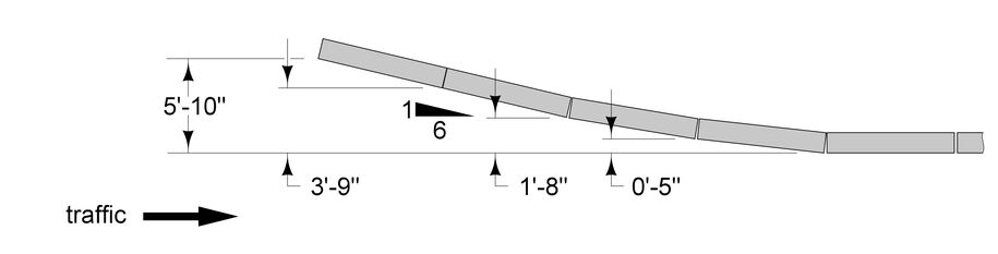
Figure 1: Concrete TBR Transition to 6:1 flare.
Back to topEnd Treatments
The end of the TBR must be protected if it terminates within the clear zone distance of the temporary traffic control zone (see Section 8A-2) for approaching traffic.
Consider these options for end treatment:
Flare the TBR beyond the temporary traffic control clear zone distance.
Where posted speed limit is 35 mph or less, the tapered end section on BA-104 is considered adequate end treatment for concrete TBR.
Protect the approach end of TBR with a crash cushion. See Section 8C-5 for specific requirements and limitations for crash cushions.
On high-speed roadways, offset of the barrier end treatment a minimum of 5 feet from the edge of the traveled way.
Crash Cushions
Truck or Trailer Mounted Attenuators
A truck or trailer mounted attenuator (TMA) is an energy absorption device that can serve as a temporary barrier when placed between live traffic and a work area on high-speed highways that must remain open to traffic during repairs or accidents. The TMA may significantly help to minimize injuries or fatalities associated with a collision between a vehicle and a truck used for protecting (blocking) a work area.
Truck Mounted Attenuators should be used on high-speed roadways to protect people, equipment, and or materials in a work or accident area that is part of a closed traffic lane and/or shoulder while the road remains open to traffic. They are especially useful for short-term operations when positive protection is needed but it may not be possible to install fixed barriers (e.g. short-term bridge work) For workspaces separated by more than 1000 feet, TMAs should be use ahead of additional workspaces. TMAs can be used for both stationary and moving operations. Diagrams showing the proper use of TMAs can be found in the Manual of Uniform Traffic Control Devices (MUTCD), Part 6 and certain TC Standard Road Plans..
Proper deployment of TMAs requires that they be positioned with sufficient roll-ahead distance between the TMA and the workspace. The roll-ahead distance is a buffer so that when a TMA is impacted, there is room for it to move with the impact without entering the workspace. TMAs have different roll-ahead distances that depend on its design and the vehicle to which it is attached. Roll ahead distances are indicated on Standard Road Plans when TMAs are required.
Regarding pilot car operations and TMA usage: Since pilot car operations are designed to operate at speeds of 40 mph and less, TMAs are not normally required for this type of work zone traffic control operation.
Back to topTemporary Crash Cushions
Refer to 8C-5 for information on temporary crash cushions in work zones
Back to top