
Content Information
On this page...
Quick Tips
A formal design exception for horizontal alignments relates only to the horizontal curvature.
Horizontal alignment has influence over other controlling criteria. Examples are design speed, stopping sight distance, and superelevation.
See Section 6D-1 for criteria on measuring sight distance on horizontal curves.
See Section 2B for superelevation criteria.
Simple and Compound Horizontal Curves
A simple circular curve is a constant radius arc used to join two tangents. Figure 2A.1 shows the components of a simple horizontal curve.

Figure 2A.1: Components of a simple horizontal curve.
Compound horizontal curves consist of two curves joined at a point of tangency and on the same side of a common tangent. Though their radii are in the same direction, they are of different values. The most common used compound horizontal curve designs are two-centered and three-centered. Figure 2A.2 illustrates two- and three-centered compound horizontal curves. Curves may have four or more centers; however, these are complicated to compute and stake. Consider a practical limit of three curves for design of compound curves.
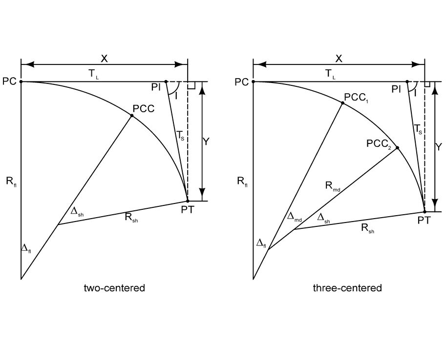
Figure 2A.2: Components of two- and three-centered compound horizontal curves.
Design Considerations for Simple and Compound Horizontal Curves
The following is a list of best practices that should be considered where practical.
Horizontal Sight Distance
Physical features along the inside of a curve can restrict distance. See Section 6D-1 for measuring sight distance along the inside of a curve.
Superelevation
See Section 2B for superelevation rates, transitions, and considerations for pavement drainage.
Minimum Radius
Try to avoid the use of the minimum radius for design. Actual speeds exceeding the design speed increase the potential for trucks overturning and run-off-the-road crashes. Additionally, drivers will track a path sharper than the real radius of a curve.
Coordination with Vertical Alignment
Horizontal and vertical alignments be designed jointly. Horizontal and vertical curves superimposed upon one another (i.e., horizontal and vertical Pls at about the same stations) limit the number of sight distance restrictions.
Try to avoid a horizontal curve at or near the high point of a crest vertical curve because drivers cannot see the horizontal change in an alignment. A horizontal curve that leads into the vertical curve provides sight distance. Decision sight distance to the point of curvature is a desirable design. See Section 6D-1 for decision sight distance.
Coordination with Bridge Design
Try to avoid horizontal curves on bridges because a bridge on a tangent alignment is more economical to construct than a bridge on a curve. If this can’t be avoided, design the alignment to avoid superelevation transition on the bridge.
Intersection
Try to avoid horizontal curves through intersections. Assessing gaps along a curved road is difficult for drivers stopped at the sideroad. Evasive maneuvers at intersections are difficult when driving through a horizontal curve.
Earthwork
Coordinate the alignment to follow natural contours. This prevents alignments that slash the natural terrain and minimizes cut and fill.
Minimum Length of Curve
Long horizontal curves improve the aesthetics of a roadway.
Design two lane highways and expressways with a minimum length of fifteen times the design speed.
Design fully access controlled roadways with a minimum length of thirty times the design speed. When thirty times the design speed cannot be achieved, use the greatest attainable length, but not less than fifteen times the design speed.
Design interstates with a minimum length of thirty times the design speed. Physical and economic constraints could limit the curve length in urban areas.
Physical and economic constraints factor into the length of curve on a low speed urban roadway.
Physical and economic constraints factor into the length of curve on a ramp. For aesthetics, a length of about 300 feet is enough for ramps.
Maximum Deflection Angle without a Curve
Alignments for two lane roadways and expressways can be designed without a horizontal curve, if the deflection is small and aesthetics is not affected. As a guide, a deflection angle of about 1.5 degrees will likely not affect aesthetics.
Interstates and full access controlled facilities are to be designed with horizontal curves. Deflection angles without a curve are not to be used on these highways.
Definitions and Formulas for Simple Curves and Compound Curves
Definitions
PI = Point of Intersection of back tangent and forward tangent.
PC = Point of Curvature. This is the point of change from back tangent to circular curve.
PCC = Point of Compound Curvature for compound horizontal curves.
PT = Point of Tangency. This is the point of change from circular curve to forward tangent.
LC = Total chord length, or long chord, from PC to PT in feet for the circular curve.
D = Degree of curvature. The central angle which subtends a 100 foot arc, see Figure 2A.1. The degree of curvature is determined by the appropriate design speed.
∆ = Intersection (or delta) angle between back and forward tangents.
I = Total intersection angle of a compound horizontal curve.
∆fl = Intersection angle (decimal degrees) of the flattest curve of a compound horizontal curve.
∆md = Intersection angle (decimal degrees) of the middle curve of a compound horizontal curve.
∆sh = Intersection angle (decimal degrees) of the sharpest curve of a compound horizontal curve.
T = Tangent distance in feet. The distance between the PC and PI or the PI and PT.
TL = Long Tangent of a compound horizontal curve.
TS = Short Tangent of a compound horizontal curve.
X = Distance from PC to PT of a compound horizontal curve in the direction of the backward tangent.
Y = Perpendicular distance of a compound horizontal curve from the backward tangent to the PT.
L = Total length in feet of the circular curve from PC to PT measured along its arc.
E = External distance (radial distance) in feet from PI to the midpoint of the circular curve.
R = Radius of the circular curve measured in feet. The radius is determined by the appropriate design speed. Sections 1C-1 and 2B of provide further information, or see the AASHTO Greenbook.
Rfl = Radius of the flattest curve of a compound horizontal curve.
Rmd =Radius of the middle curve of a compound horizontal curve.
Rsh =Radius of the sharpest curve of a compound horizontal curve.
θ = Deflection angle from a tangent to a point on the circular curve.
∆/2 = Deflection angle for full circular curve measured from tangent at PC or PT.
C = Chord length in feet, where a chord is defined as a straight line connecting any two points on a curve.
S = Arc length in feet along a curve.
MO = Middle ordinate. Length of the ordinate from the middle of the curve to the LC.
Formulas
Two-Centered Compound Curves
\(I = \Delta_a + \Delta_{sh}\)
\(X = R_{sh}\,\sin(I) + (R_a - R_{sh})\,\sin(\Delta_a)\)
Three-Centered Compound Curves
\(I = \Delta_{fl} + \Delta_{md} + \Delta_{sh}\)
\(X = (R_{fl} - R_{md}) \times \sin(\Delta_{fl}) + (R_{md} - R_{sh}) \times \sin(\Delta_{fl} + \Delta_{md}) + R_{sh} \sin(I)\)\(Y = R_{fl} - R_{sh} \times \cos(I) - (R_{fl} - R_{md}) \times \cos(\Delta_{fl}) - (R_{md} - R_{sh}) \times \cos(\Delta_{fl} + \Delta_{md})\)
\(T_L = \frac{ R_{sh} - R_{fl} \times \cos(I) + (R_{fl} - R_{md}) \times \cos(\Delta_{md} + \Delta_{sh}) + (R_{md} - R_{sh}) \times \cos(\Delta_{sh}) }{ \sin(I) }\)\(T_S = \frac{ R_{fl} - R_{sh} \times \cos(I) - (R_{fl} - R_{md}) \times \cos(\Delta_{fl}) - (R_{md} - R_{sh}) \times \cos(\Delta_{fl} + \Delta_{md}) }{ \sin(I) }\)
Back to topReverse Curves
This section provides information related to the design of reverse curves. Common uses of reverse curve are:
- To redirect through lanes at channelized intersections and high speed median crossovers,
- In interchange ramp alignments, and
- To realign crossroads at skewed intersections.
A reverse curve is two or more simple curves turning in opposite directions (see Figure 2A.3). The curves may have equal or unequal radii and/or deflection angles.
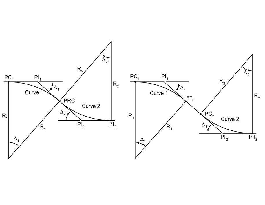
Figure 2A.3: Reverse curves without and with tangent section in between.
Back to topDesign Considerations for Reverse Curves
Distance Between Reverse Curves
The distances for superelevation transitions should be considered between horizontal curves.
The minimum tangent length between the curves is equal to the sum of 70% of the tangent runoff length (L) of each curve. Consider each of the curves in a reverse curve in a similar manner as a horizontal curve as described above in this section. Section 2B provides more information related to superelevation.
Channelized Intersections
Consider the design of reverse curves at a channelized intersection, see Figure 2A-4.
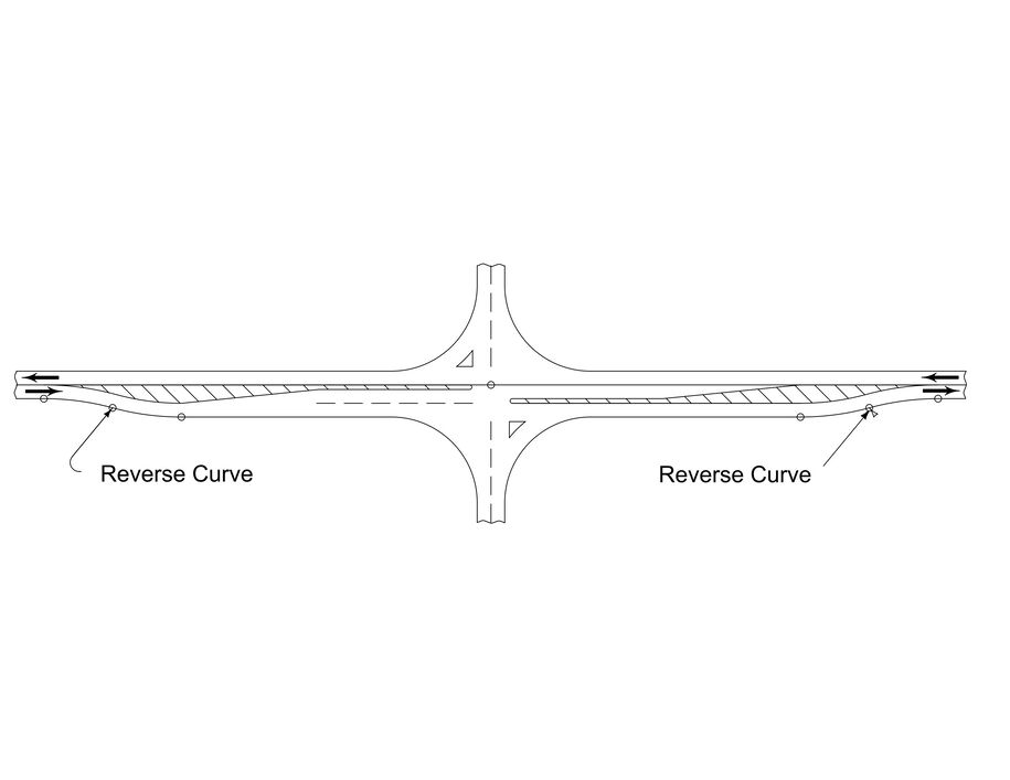
Figure 2A.4: Reverse curves at a channelized intersection.
Superelevation is undesirable at channelized intersections with redirected through lanes. Past design practice was to use a 0º30ʹ degree of curvature (12,000 feet radius equivalent). Current practice is to select minimum radii to allow normal crown slopes at design speed with the curves located adjacent to one another. See Section 6A-1 for more information on auxiliary lane design.
Median Crossovers
Section 3E-3 provides information related to median crossovers. The designer is encouraged to consult the Methods Section in the Design Bureau for further assistance with median crossover design.
Interchange Ramp Alignments
Use reverse curves at interchange ramps when necessary. Design tangent sections between the curves to accommodate the high speed superelevation transitions.
Realignment of Crossroads
Use reverse curves when realigning crossroads to reduce skew. See Section 6A-8 for more details concerning intersection alignment.
Example: Lane Redirection at an Intersection
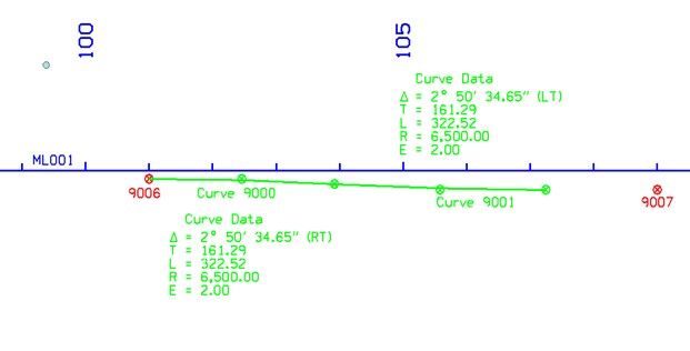
Given a design speed of 50 mph and a lane width of 12 feet, we wish to design a reverse curve to redirect a through lane to accommodate a 16 foot median for a left turn lane, as seen in Figure 2A.5. Assume a normal crown (NC) section.
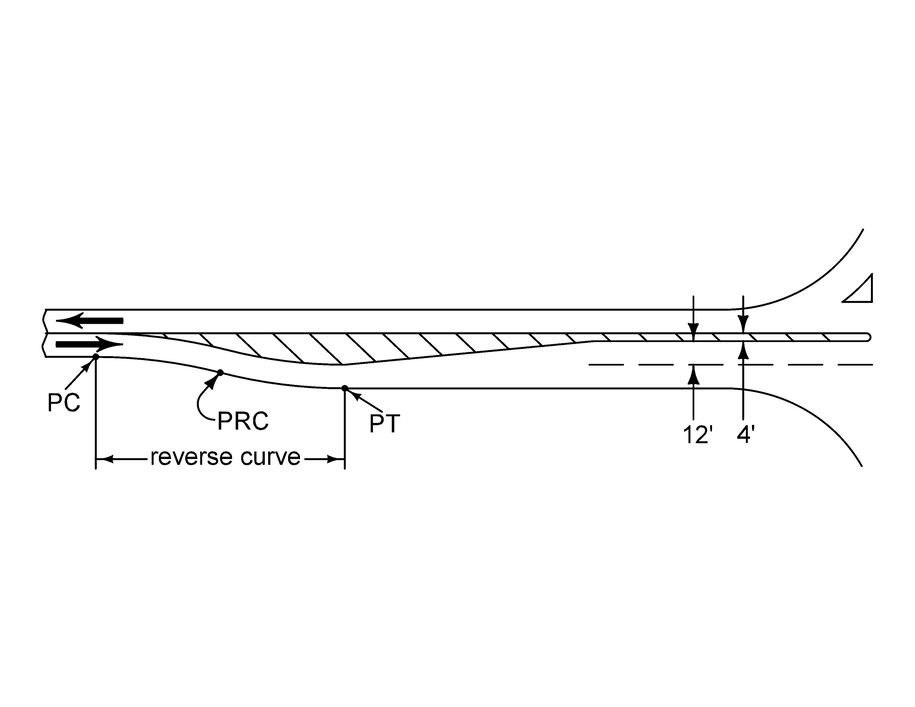
Figure 2A.5: Reverse curve used to redirect a through lane at an intersection.
Using Table 2 in Section 2B-3 with a normal crown (NC), R = 7,870 feet.
Spiral Curves
Spiral curves are generally used to provide a gradual change in curvature from straight section of road to a curved section. They assist the driver by providing a natural path to follow. Spiral curves also improve the appearance of circular curves by reducing the break in alignment perceived by drivers. Figure 2A.6 shows the placement of spiral curves in relation to circular curves. Figure 2A.7 shows the components of a spiral curve.
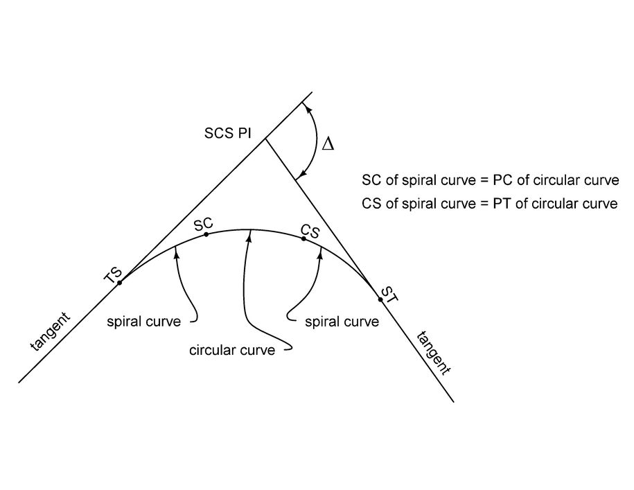
Figure 2A.6: Placement of a spiral curve.
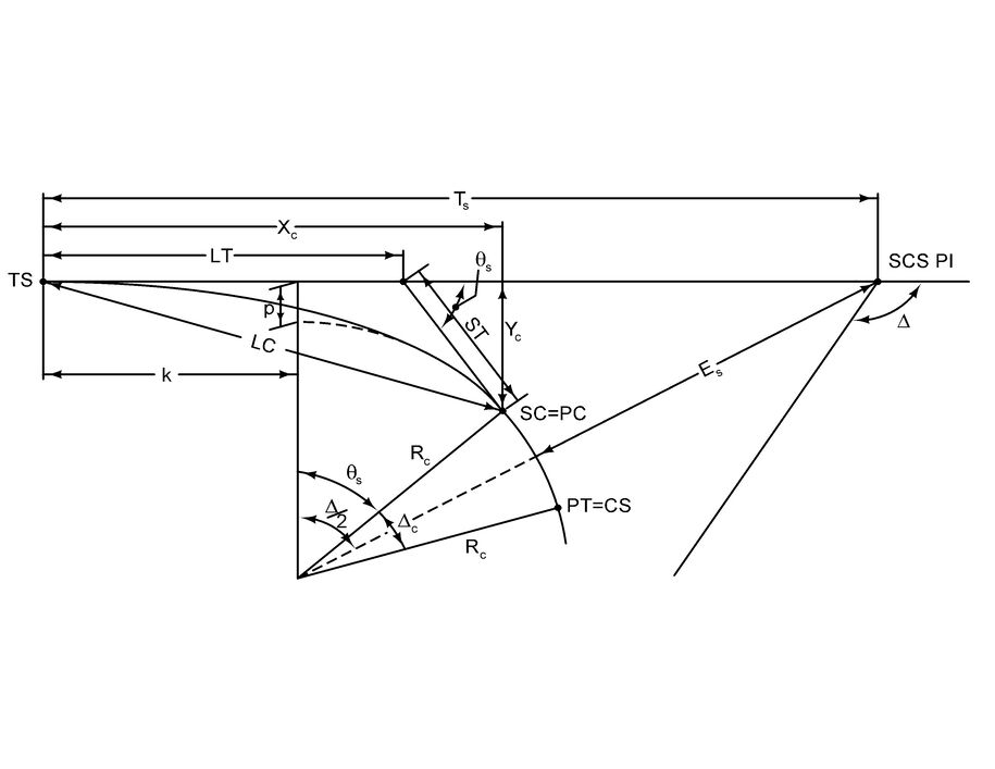
Figure 2A.7: Components of a spiral curve
Back to topDesign Considerations on Spiral Curves
Spiral Curve Transitions
Spiral curves can be designed for high speed roadways; however, the Iowa DOT rarely uses spiral curves on current designs. Drivers gradually turn into curves, with the path following a spiral curve. Roadway segments with spiral curve transitions have the potential for fewer crashes than segments without spiral curve transitions.
Spiral Curves on Bridges
Try to avoid spiral curves on bridges. The designer should select a curve radius which doesn’t require a spiral curve.
Definitions and Formulas for Spiral Curves
SCS PI = Point of intersection on main tangents.
TS = Point of change from tangent to spiral curve.
SC = Point of change from spiral curve to circular curve.
CS = Point of change from circular curve to spiral curve.
ST = Point of change from spiral curve to tangent.
LC = Long chord.
LT = Long Tangent.
ST = Short Tangent.
PC = Point of curvature for the adjoining circular curve.
PT = Point of tangency for the adjoining circular curve.
Ts = Tangent distance from TS to SCS PI or ST to SCS PI.
Es = External distance from the SCS PI to the center of the circular curve.
Rc = Radius of adjoining circular curve.
Dc = Degree of curve of the adjoining circular curve, based on a 100 foot arc (English units only).
D = Degree of curve of the spiral at any point, based on a 100 foot arc (English units only).
I = Spiral arc from the TS to any point on the spiral (I = Ls at the SC).
Ls = Total length of spiral curve from TS to SC (typically the superelevation runoff length, see Section 2B).
L = Length of the adjoining circular curve.
θs (or Theta) = Central (or spiral) angle of arc Ls.
∆ = Total central angle of the circular curve from TS to ST.
∆c = Central angle of circular curve of length L extending from SC to CS.
p = Offset from the initial tangent.
K = Abscissa of the distance between the shifted PC and TS.
Yc = Tangent offset at the SC.
Xc = Tangent distance at the SC.
x and y = Coordinates of any point on the spiral from the TS.
Back to top