Content Information
On this page...
- Identification of Noise Wall Location
- Determination of Noise Wall Structure Type
- Development of Noise Wall Horizontal Alignment
- Development of Preliminary Alignment and Cross Sections
- Development of Existing Ground, Noise Wall Top, and Proposed Ground Profiles
- Development of Noise Wall Bottom Profile
The Design Bureau is responsible for preparing or approving preliminary and final design plans, including landscaping, for traffic noise abatement projects. Refer to Policies and Procedures Manual PPM 500.07 for additional information on the Department’s polices, interoffice responsibilities, and procedures for highway traffic noise analysis and abatement relating to the Code of Federal Regulations (23 CFR 772).
As is noted at the end of this section, a preliminary design including noise wall locations, lengths, and heights should be prepared for the D2 event (Design Field Exam). Since the final design may have right of way impacts, it should be completed by the D5 event (Plans to Right of Way).
Back to topIdentification of Noise Wall Location
The Office of Location and Environment is responsible for the identification of likely noise wall locations during the NEPA process. The location described typically includes a range of homes designated for noise protection. The designer, in consultation with the Office of Location and Environment, determines the physical location (offset from adjacent roadway(s) and length) of the wall. Some factors that aid in the determination of feasibility and reasonableness include the anticipated noise reduction effectiveness of the wall, the cost per benefitted receptor, the anticipated noise level, and public desire, among other factors.
Back to topDetermination of Noise Wall Structure Type
Verify the noise barrier type (i.e., wood, concrete, or composite wall, or earthen berm) through coordination with the District and the Office of Bridges and Structures.

| NOTE: The values provided in Tables 1 and 2 are specific to precast concrete noise walls. If a different wall type is specified, the designer is responsible for confirming the specific geometric requirements of the specified wall type with the Office of Bridges and Structures. |
|---|
Development of Noise Wall Horizontal Alignment
The horizontal alignment is influenced by multiple factors, including but not limited to the following:
- Consideration of right-of-way availability and proximity of wall location.
- Consideration of the optimal location to minimize wall height requirements.
- Provision of adequate drainage including ditching, evaluation of obstructions of any current drainage ways or storm water runoff paths, and consideration of water passing under the wall.
- Consideration of normal column spacing impacts on new and existing utilities and the necessity for utility bridges/grade beams if normal spacing is not achievable.
- Contact the Foundations Field Engineer in the Office of Construction for guidance pertaining to crossing utilities or culverts and necessary clearance.
- Consideration of the most effective location of the wall for noise reduction and overall constructability.
- Consideration of the feasibility of maintenance of the residential side of the wall.
- Consideration of design coordination with any retaining walls.
- If it is an MSE retaining wall, are noise wall columns within the strap zone?
- Consideration of impacts of design on historically sensitive areas and the potential necessity of special measures to restrict/monitor vibrations.
When determining the alignment of the noise wall, tangent lengths must be divisible by the column spacing. Critical points along the alignment should be considered first. Examples of critical points include arrangement of columns to span existing utilities and the desirability of locating bends to mirror right-of-way. Bends must be designed per the allowable horizontal deflections. Refer to Table 1 below for column spacing and allowable alignment deflection guidance.
To complete this process, the noise wall alignment should be stored as a chain in Geopak. The noise wall alignment, as well as column spacing, should be drawn in the plan view using D & C Manager. Refer to Section 20D-2 for chain naming guidelines.
NOTE: The designer must accurately reflect the column spacing in the plan view.
Back to topDevelopment of Preliminary Alignment and Cross Sections
Preliminary cross sections should be developed along the noise wall chain using Corridor Modeler. As a preliminary first step in defining the wall height, these cross sections are used to draw a line connecting the Stack Height and Receptor Height, (minimum wall height intersect line), which is used to develop the proposed ground and top of wall profiles.
Stack Height refers to the sound producer, which is assumed to be the height of exhaust from a semi. The Stack Height is typically measured at 14 feet above the roadway surface. The existing topography and superelevation of the proposed roadway should be studied to determine if the Stack Height should be applied at the nearest lane or the farthest lane of traffic (see Figure 1).
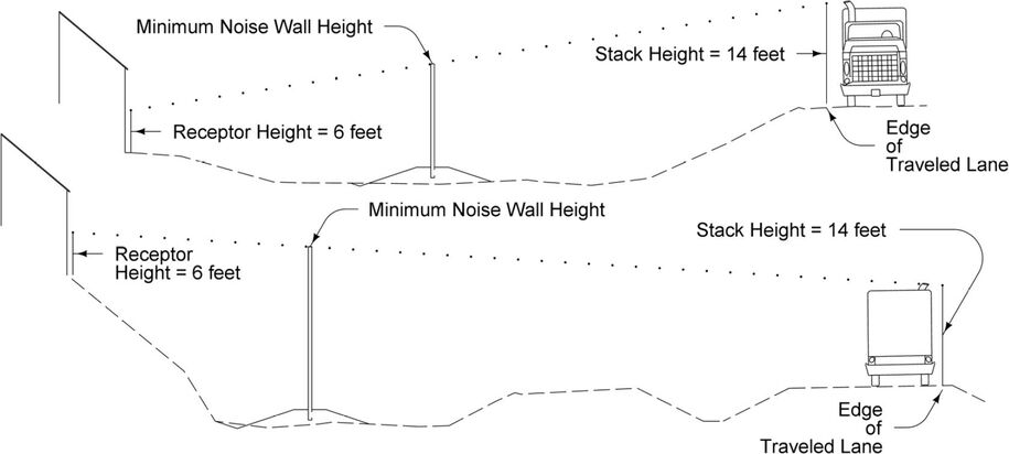
Figure 1: Development of Preliminary Cross Sections.
Receptor Height refers to the individual that will hear the sound produced and is measured at a height of 6 feet above existing ground (the estimated height of a person). The Receptor Height coincides with the ‘Exterior Area of Frequent Human Use’ as defined in the Policies and Procedures Manual PPM 500.07 and is to be applied at ‘a clearly defined exterior space such as a deck, patio, screened porch, or balcony’.. The Receptor Height measurement location is to be interpolated between homes.
Site-specific conditions, such as the location of the ‘Exterior Area of Frequent Human Use’ must be studied to determine the location where the Receptor Height is applied. For example, in Figure 2, below, the ‘Exterior Area of Frequent Human Use’ for ‘Home 1’ is on the side of the house farthest from the roadway (the location of a deck) but for ‘Home 3’ it is on the side of the house nearest to the roadway (the location of a patio).
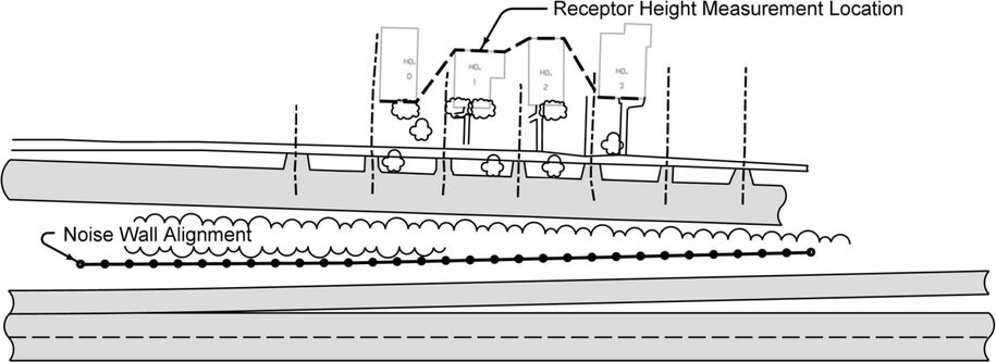
Figure 2: Receptor Height Measurement.
The outermost receptors (Home 0 and Home 3) should be protected from a noise source a distance four times the perpendicular distance between the receptor and source, as measured along the noise wall alignment, to determine if appropriate wall length has been established (see Figure 3).
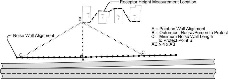
Figure 3: Sound Protection of Receptor along Noise Wall Alignment.
The receptor height measurement location line should be drawn into the Road_Design_Linework model of the Roadway Design File (*.dsn) to be imported into Corridor Modeler as plan graphics. Refer to Section 20B-71 for more information on design file structure and model contents. Review the Receptor Height Measurement Location with the Office of Location and Environment. A template is available in the Corridor Modeler template library to aid the designer in determining if the preliminary alignment is feasible or if adjustments should be made. The template library may be obtained by accessing the CopySeed program (see Section 21C-54). Point Controls can be set in Roadway Designer using the appropriate plan graphics stored to control the Stack and Receptor Locations. The initial template will then draw the wall height based on the intersection of the intersect line and face of the noise wall alignment. Preliminary shaping between the roadway and the noise wall is developed as well (see Figure 1).
Refer to Section 21B-200 for guidance on GEOPAK Corridor Modeler. Refer to Section 21B-224 for guidance on Corridor Modeler template details.
Create a cross section design file and draw the preliminary cross sections for the noise wall. Draw and review cross sections at every column location. Refer to Section 21B-250 for further guidance on drawing cross sections. At this point, the noise wall height is drawn to its interception with the intersect line (ie. the minimum wall height has been established).
Back to topDevelopment of Existing Ground, Noise Wall Top, and Proposed Ground Profiles
Existing Ground Profile
Begin by creating and plotting the existing ground profile for the noise wall alignment. Refer to Section 21A-202 for information regarding drawing profiles (see Figure 4).
Noise Wall Top Profile
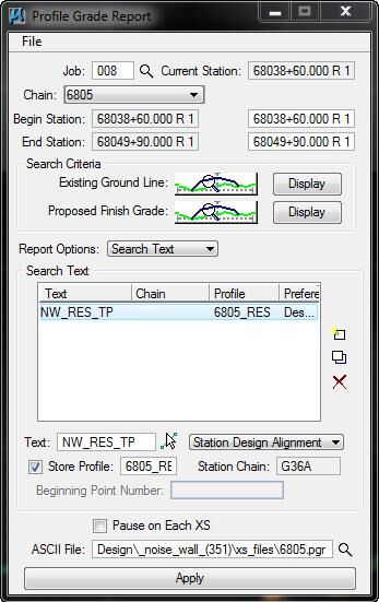
The minimum required noise wall height is now extracted from the preliminary cross section file and plotted as a profile (see Figure 4). This minimum noise wall height can be obtained by browsing to Applications > GEOPAK > ROAD > Cross Sections > Reports and running a Profile Grade Report. Toggle the Report Options dialog to Search Text to target the noise wall top, as shown at right. This report will serve as a baseline for designing the top profile of the noise wall.
Before development of the top profile, the column spacing should be marked on the profile (see Figure 4). The column spacing corresponds to the locations where the top profile may change elevations by stepping up or down. Table 2 summarizes the characteristics of panels that control steps in the noise wall profile as well as wall height requirements. The top profile should minimize elevation steps and create a symmetrical and/or balanced appearance while extending above the sound vector (see Figure 4).
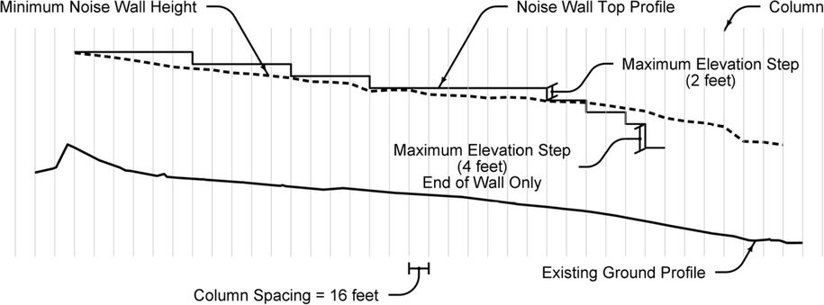
Figure 4: Existing Ground, Minimum Noise Wall Height, and Noise Wall Top Profiles.
The ‘Minimum Noise Wall Height’ profile may be sufficient for the protection of the receptor from a noise source that is directly perpendicular to the receptor (see AB in Figure 3).
Proposed Ground Profile
To create the proposed ground profile, review the proposed grading of the wall in connection with the existing ground and any other grading in the vicinity. Often the noise wall will be constructed above the existing ground on a berm to provide adequate relief to develop ditches and prevent water accumulation along the noise wall. The proposed ground profile should contain a minimal number of VPIs (Vertical Points of Intersection) to create a smooth appearance along the wall (see Figure 5).
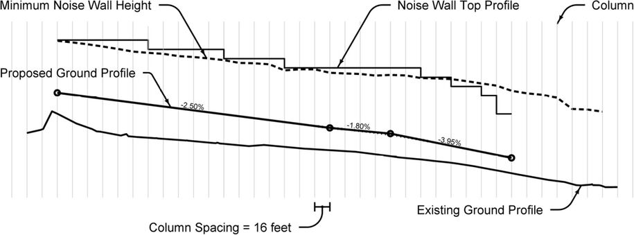
Figure 5: Proposed Ground Profile.
Back to topDevelopment of Noise Wall Bottom Profile
Once the top profile and the proposed ground profile are completed, the bottom profile can be determined by optimizing the panel arrangement, which is controlled by the panel height. Note that the profile must extend below the proposed ground profile, thereby ensuring there are no “leaks” in the sound protection. Refer to Table 3 for panel embedment depths.
The goal of optimization is to minimize the amount of the noise wall that is buried (see Figure 6). Minimal embedment also helps facilitate the passage of drainage structures and utilities under the noise wall. To help minimize embedment, the use of half panels may be used.
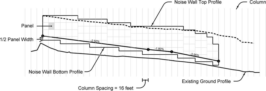
Figure 6: Noise Wall Bottom Profile.
Back to topFinal Template Adjustment
At this point, all noise wall profile elements are completed (top, footing, and proposed ground) and the constraints should be applied to the noise wall template so that the height, ground profile, and embedment of the wall are shown correctly.
The wall should be constrained using the noise wall top profile, proposed ground profile, and footing profile. The top of the noise wall should now extend above the original intercept of the sound vector. Adjustments can be made to the proposed ground profile in order to achieve proper grading slopes. In situations of steep slopes and/or restrictive alignment placement, a split ground profile may be used (see Figure 7). If the differential of the split profile is limited to 2 feet or less, special design is not necessary. Split profiles should be avoided whenever possible. Notify Soils Design and the Office of Bridges and Structures of plans to use split ground profiles.
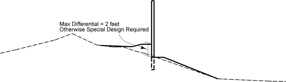
Figure 7: Split Profile.
Back to topDesign of Drainage Structures and Utility Crossings
With the completed cross sections and the footing elevation, intakes and letdown pipes can be designed. When determining whether to use an intake or pipe, consideration should be given to the outlet: can ditches be utilized or is runoff conveyed into a storm sewer system? The pipe and utility crossings are to be drawn in the plan and profile views and on the cross sections.
All existing utility crossings need to be plotted on the noise wall profile. If the elevation is unknown, it should be flagged as approximate and must be field verified. Those same crossings should be placed on the cross section that is nearest to the actual crossing.
Back to topContact Soils Design Section
After the District and/or Utilities personnel have reviewed the preliminary plan, then the Soils section can be notified of the final alignment and a copy of the plans should be given to them. The Soils section will prepare the soils sheets for the final plan.
Back to topPreparation of the TS&L by the Office of Bridges and Structures
A preliminary type, size, and location (TS&L) is prepared by the Preliminary Section in the Office of Bridges and Structures for the D2 event (Design Field Exam). Upon receipt of the D3 submittal (Plans for Preliminary Bridge), the Office of Bridges and Structures will prepare the final TS&L for the B1 submittal (Bridges and Structures Layout).