Content Information
On this page...
5A-1 Earthwork Essentials
Before beginning any earthwork project, designers should have a basic understanding of the soil classifications, as well as earthwork classifications and construction specifications, which dictate the removal, placement, and quantification of earthwork materials. They should also be familiar with the standard plans that govern placement of certain materials, and the engineering properties of the materials that may be encountered during excavation.
The types of soils that exist within the project corridor will determine the complexity of the earthwork calculation process. The physical characteristics and location of these materials will determine how they should be excavated and placed within the project limits, how long it may take the contractor to excavate or re-compact the soil, and more importantly, how much it will cost to do either.
This section provides designers with a basic understanding of the following topics:
- Soils Classifications – A general understanding of the Iowa DOT soils classification process.
- Roadway and Borrow Excavation Classifications – Description of Iowa DOT soils classifications.
- Earthwork Standard Road Plans – General requirements of how different soils are to be removed and\or placed within the project embankment. Refer to the EW Series Standard Roads Plans to access all applicable design criteria.
- Earthwork Payment Items, Methods, and Tabulations – An overview of the different payment methods for earthwork and necessary tabulations that accompany these payment methods. Refer to 5A-2, Section 5C, and the Road Design Details to access additional applicable design criteria.
- Shrink and Swell Factors – Definitions of Shrink and Swell factors and how they affect earthwork calculations.
- Manual Plus Cuts and Fills – Method of adding or subtracting additional soil volumes to the cross sections
The Soils Design Section uses soil borings and other methods to determine the approximate location, depth, and types of soils anticipated to be encountered during construction. This information is typically provided in profile view on the Soils Q sheets and on the Design cross sections using soil meshes developed in CADD by the Soils Design Section. The CADD soil meshes are used by the roadway designers to calculate earthwork material volumes.
The soil profiles are plotted on the profile sheet, along with locations of subgrade treatment or unsuitable soils. Subsurface soil classification meshes are plotted on the Design cross sections, refer to Section 1F-16.
Back to topSoil Classifications
To provide a common language and a general guide to their engineering behavior, soils are classified using either the Unified Soil Class System (USCS) (ASTM D 3282), “Standard Practice for Classification of Soils and Soil-Aggregate Mixtures for Highway Construction Purposes” or the AASHTO Classification System (AASHTO M 145), “Standard Specifications for Classification of Soils and Soil-Aggregate Mixtures for Highway Construction Purposes”. The Soils Design Section typically uses the AASHTO classification system. This system classifies soil into seven major groups from A-1 through A-7 as follows:
Group Classification
A-1 through A-3 Granular Type Materials
A-4 through A-7 Silty Clay Type Materials
Soils available for embankment construction in Iowa generally range from A-4 soils, which are very fine sands and silts that are subject to frost heave, to A-6 and A-7 soils, which predominate across the state. The A-6 and A-7 groups include shrink/swell clayey soils. In general, these soils rate from poor to fair in suitability as subgrade soils.
Because these are marginal soils, it is critical that the embankments be constructed with proper compaction and moisture content, and in some cases, stabilization. See Section 200F-9 for geosynthetic stabilization guidance or consult with the Soils Design Section for other types of stabilization.
The importance of understanding different soil types cannot be overemphasized. Certain soil types classified as unsuitable material have to be placed in the proper location because of their engineering characteristics. Standard Road Plans EW-101 and EW-102 (discussed later in this section) show proper placement of these materials.
Back to topRoadway and Borrow Excavation Classifications
The Iowa DOT Standard Specifications divide Roadway Borrow and Excavation into different classifications based on the level of effort required to excavate the material. Class 10, Class 12, Class 13, and Borrow (Embankment-in-Place and subgrade treatments) are the major classifications and are described as follows.
Class 10
This classification includes all normal earth materials such as loam, silt, gumbo, peat, clay, sand, and gravel. Class 10 material is further divided into Suitable Soils and Unsuitable Soils. These are described in more detail later in this section.
Unsuitable soils are further divided into Type A (UNS A), Type B (UNS B), Type C (UNS C) and Slope Dressing (Peat/Muck). These unsuitable soils may be used in embankments according to Standard Road Plan EW-102 and Table 2102.02-1 of the Standard Specifications.
Class 12
This classification is commonly referred to as Rock Excavation. Excavation requiring ripping, blasting, or other methods to remove granite, quartzite, chert, limestone, sandstone, shale and slate is considered Class 12 Excavation.
Boulders that due to size, number, or location prevent them from being handled similar to soil, should be bid as Excavation, Class 12: Boulder/Rock Fragment.
Boulders that have been classified as Class 12 excavation may be placed into the embankment according to Article 2102.03, C, 3 of the Standard Specifications, or with the Engineer’s approval, may be placed according to Article 2102.03, C, 4 of the Standard Specifications.
Class 13
This classification is commonly referred to as Unclassified Excavation. Class 13 includes all materials listed under the definitions of Class 10 and Class 12, and any other materials encountered regardless of nature.
The contract documents will specify the limits of Class 13 excavation. Excavation within these limits will not be classified as Class 10 or Class 12. This material is not commonly handled in the earthwork calculation spreadsheet.
Embankment-in-Place
When the quantity of material required for the roadway embankment is not available within the limits of the roadway cross sections, it will need to come from another location.
Select Treatment Material
Select Soils used for subgrade treatment must meet the following criteria, except Proctor, if a Proctor test was not taken.
Cohesive Soil (Select Loam)
Meet the requirements of Article 2102.02, D, 1, a of the Standard Specifications.
Granular Soil (Select Sand)
Meet the requirements of Article 2102.02, D, 1, b of the Standard Specifications.
Back to topEarthwork Standard Road Plans
Standard Road Plans EW-101 and EW-102 demonstrate the proper excavation, placement methods, and treatment of the different soil types that may be encountered during the design and construction of a project. These standards provide details for the construction of roadway embankments, allowable placement of unsuitable materials, subgrade treatments, moisture and density control, topsoil spreading, plowing and shaping, and special compaction requirements.
Standard Road Plan EW-101 – Embankment and Rebuilding Embankments
This standard illustrates the normal construction procedures for the excavation and rebuilding of embankments, The key difference between each of the typical cross sections for rebuilding of embankments is the location of the natural ground line. The intent is to excavate a uniform layer down to existing embankment line, or a distance “D” below finished grade line, whichever is higher. The detailed project design cross sections should reflect the intent of these typical cross sections shown in this standard.
The dimension “D” will be defined in Tabulation 107-31.
Standard Road Plan EW-102 – Allowable Placement of Unsuitable Soil in Embankments.
Unsuitable Soils
As previously discussed, unsuitable soils are classified as Type A (UNS A), Type B (UNS B), and Type C (UNS C) and should be placed in embankment construction as outlined in EW-102. Table 2102.02-1 in Article 2102.02, D, 3 of the Standard Specifications defines the various types and uses of unsuitable soils. The table is arranged from highest quality to lowest quality soil. The Type A, Type B, and Type C placements of Table 2102.02-1 correspond to the Type A, Type B, and Type C placements shown on EW-102.
Fill Areas Greater than 20 Feet in Height.
In new embankments greater than 20 feet in height, only Select, Suitable Class 10, or Type ‘C’ Unsuitable material will be allowed below that 20 foot depth.
Back to topShrink and Swell Factors
Shrink and swell factors are determined by the Soils Design Section and provided to the designer. These factors are a function of the material’s physical characteristics and should be accurately determined prior to beginning earthwork operations to estimate the earthwork quantities. Refer to Section 200B-3 for guidance on shrink and swell factors.
Back to topCalculations for Earthwork
Determining quantities for earthwork items is a multi-step process. Refer to Section 5C for guidance on earthwork calculations
Manual Plus Cuts and Fills
When determining earthwork volumes for a roadway, there will be instances where additional volumes will still need to be added to the earthwork spreadsheet quantity to account for areas not included in the average end area calculations. Examples of these areas may be:
- Median crossovers (see PV-500s).
- Rural entrances (see EW-501).
- Safety ramps (see EW-502).
- Maintenance turnarounds (see Road Design Detail 8101).
- Ditch checks (see EW-110).
- Wing dikes (see EW-210).
- Guardrail blisters (see EW-301).
Several methods may be used to calculate volumes for these additional areas:
- Accurate modeling of the corridor using ORD Connect Corridor Modeler will provide the means to compare the proposed finished grade with the existing ground line to determine volumes. Refer to Section 5C for guidance on earthwork calculations, including creating earthwork report from Open Roads Designer (ORD).
- Manual Calculations – May be sufficient for most cases.
The accuracy of the calculations depends on the accuracy of the end areas. Therefore, each time the geometry of the entrance changes, a new end area should be calculated. Figure 5A.2 illustrates needed end areas for an entrance.
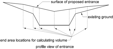
Figure 5A.2: Needed end areas for calculating volume at an entrance.
The areas of ditch checks, safety ramps, entrances, etc. may be calculated manually by using the areas in Figures 5A.3 and 5A.4.
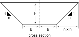
Figure 5A.3: End area for ditch checks, entrances, etc.
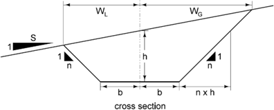
Figure 5A.4: End area for ditch checks, entrances, etc. with a sloping ground line.
Assuming a cut (or fill) such as the one in Figure 3, the cross sectional area is given by:
Area = 2bh + \(nh^2\) = h(2b + nh)
Assuming a cut (or fill) such as the one in Figure 4, the cross sectional area is found first by calculating \(W_L\) and\(W_G\):
\(W_L\) = S(b + n h) / (S + n) and \(W_G\) = S(b + n h) / (S - n)
Depending on the level of accuracy required, the volumes of these areas may be summed using the average end area formula, or if more accuracy is required, the prismoidal formula. The following Average End Area formula is defined as follows:
Where:
V = Volume
A₁ = Cross section area of first side
A₂ = Cross section area of second side
L = Length between the two areas
If one end area has a value of zero, the earthwork volume can be considered a pyramid and the correct formula would be:
A more accurate formula is the prismoidal formula, which takes out most of the error accrued by the average end area method.
Where:
V= Volume
A₁ = Cross sectional area taken at beginning of proposed element
Aₘ= Area of a plane surface midway between the two cross sections
A₂ = Cross sectional area taken at end of proposed element
Back to top
5A-2 Roadway Earthwork Bid Items Descriptions
Back to topRoadway Excavation
Typically, contractors are paid for material that is cut regardless of whether the material is from within the project or from a borrow area.
EXCAVATION, CLASS 10 ROADWAY AND BORROW: Total cut volume of Class 10 material. This does not include any shrink, wasted materials, or rock materials that will be bid as Class 12 or Class 13. A shrink factor is used on the fill side to determine this quantity.
EXCAVATION, CLASS 10, WASTE: Total cut volume of Class 10 material that will be removed from the project. Even if some of the waste material can be reincorporated back into the project, it is bid as waste. The contractor decides how to handle the excess material.
EXCAVATION, CLASS 12, BOULDER OR ROCK FRAGMENTS: Total volume of large rock material removed from, or buried on, the project. This quantity is supplied by soils design section.
EXCAVATION, CLASS 12, ROADWAY AND BORROW: Total cut volume of material indicated as rock in the cross sections. This volume should be subtracted out of the total cut when determining the Class 10 Roadway & Borrow bid item quantity. If there is room for this material in the fill, it should be placed there. If the contractor wants to use it for other purposes, it would be their responsibility to provide replacement material.
EXCAVATION, CLASS 13, ROADWAY AND BORROW: Total cut volume of any material not classified as Class 10 or Class 12 in the embankment for roadway construction.
EXCAVATION, CLASS 13, WASTE: Total cut volume of Class 13 material to be removed from the project.
EMBANKMENT-IN-PLACE: Total calculated volume of fill material needed within the template when the quantity is less than 10,000 cubic yards. No shrink factor is applied to this bid item quantity.
EMBANKMENT-IN-PLACE: CONTRACTOR FURNISHED: Total calculated volume of fill material needed within the template when the quantity is greater than or equal to 10,000 cubic yards. No shrink factor is applied to this bid item quantity.
Back to topTopsoil Excavation
TOPSOIL, FURNISH AND SPREAD: Total calculated volume of Topsoil material needed within the template brought from an outside source to be spread on a project. The bid item quantity does not include any shrink factor. However, a shrink factor is used on the cut material to determine this quantity.
TOPSOIL, SPREAD: Total calculated volume of Topsoil material needed within the template to be spread on a project. This is material already stockpiled within the project limits. The bid item quantity does not include any shrink factor. However, a shrink factor is used on the fill material to determine this quantity.
TOPSOIL, STRIP, SALVAGE AND SPREAD: Total calculated volume of Topsoil material within the template to be stripped, stored in the project limits, then placed in designated areas. The bid item quantity does not include any shrink factor. However, a shrink factor is used on the fill material to determine this quantity.
TOPSOIL, STRIP AND STOCKPILE: Total calculated template volume of Topsoil material to be stripped and saved for a later operation (excess of Topsoil material stripped after the fill quantity is satisfied). The bid item quantity does not include any shrink factor. However, a shrink factor is used on the cut material to determine this quantity.
Back to topExamples of Bid Item Usage
See Section 1F-20 for examples.
Back to topEnglish Bid Item Descriptions
Division 21 of the Standard Specifications explains the Method of Measurement and Basis of Payment for the many items related to earthwork construction for roadways. The type of materials encountered determines the Tabulations required for a project. The placement of Class 10, unsuitable soils, select backfill, and special backfill materials may have both moisture and density limit requirements. Check with the Soils Design Section to determine if moisture and density control will be required on the project.
The earthwork pay items required will depend on whether the project balances, has excess (waste) material, or requires a borrow source. The Iowa DOT master pay items list contains the excavation bid items below. Refer to the English Bid Item Descriptions for a complete list of items associated with Division 21. Table 5A.1 provides bid items descriptions that are relevant to this topics covered in this section.
Back to top