Content Information
On this page...
This section describes how to joint urban intersections by following the guidelines outlined in Section 7A-2. The process will be illustrated through an example of the intersection of a reduced-speed urban highway and a city street. The intersection is curbed, includes several intakes, and the pavement thickness is 10 inches.
Even though not all urban intersections will be exactly like the one used in this example, the process described is applicable to other layouts.
Back to topStep 1: Place Joints with Predetermined Locations
Because the location of longitudinal joints for both the mainline and the city street is predetermined by the lane widths, these joints should be placed first. As illustrated in the Typical Components, the 53 foot pavement section (4 Lane Undivided PCC backbone with curbed shoulders) used for the mainline requires a longitudinal joint down the centerline and one on each side of centerline, offset the width of a 12 foot lane. The Typical Components illustrate a similar layout for the longitudinal joints of the city street with a 31 foot pavement section (2 Lane PCC backbone with curbed shoulders).
Within the intersection, the road that is paved first determines which joints are longitudinal and which are transverse. Generally, the mainline will be paved prior to the city street. Therefore, the longitudinal joints running down the city street define the locations of the first transverse joints for the mainline (see Figure 1).
To determine an appropriate longitudinal joint to use, refer to Standard Road Plan PV-101 or Table 2 in Section 7A-2. Normally, the type of joint used depends on the pavement thickness. Since the pavement thickness is greater than 8 inches in this case, either a KT-2 or an L-2 joint is appropriate.
Back to topStep 2: Place Difficult Joints
Intake locations and the boxouts at the corner radii of the intersection are addressed next. After joints have been placed at these locations, the rest of the joints can be worked in around them.
Joints at Intakes
The location of intakes is determined before the joints are laid out, so joints have to be worked in around them. Begin by straddling the intake with two transverse joints spaced at 17 feet. These joints can be repositioned later if it aids in placing other joints. In the final layout, the intake does not have to be centered between the joints. As shown in the SW Series Standard Road Plans, the joint may be as close as 2 feet from the intake on grade and as close as 4 feet at a low point.
Standard Road Plan PV-101 and Table 1 in Section 7A-2, indicate that a CD joint should be used on the mainline since the pavement thickness is greater than 8 inches. However, the CD joints straddling the intake do not extend all the way through the curb and gutter. The joints immediately surrounding the intakes are specified in the applicable SW Series Standard Road Plan.
Joints at Boxouts
Before the mainline is paved, small areas near the corners are boxed-out. These boxed-out areas (hatched in Figure 1) are poured later, after the mainline has been paved. If the paver were to proceed straight through this area, instead of using boxouts, the returns of the city street would narrow to a point where they meet the mainline. Pavement less than 2 feet in width is weak and cracks readily. By using boxouts, this situation can be avoided without the expense of stopping the paver at the intersection.
The size and shape of boxouts varies depending on where they are used, but the width of boxouts is normally the same as the roadway’s gutter width. When placing joints around the boxout, remember to maintain intersecting angles greater than 70 degrees and joints at least 2 feet long. KT-2 or L-2 joints are used around the boxout. Figure 1 illustrates joints properly placed, both around the boxouts and extending outward from them.
Back to topStep 3: Place Remaining Joints
After the joints at intakes and boxouts are placed, the remaining joints (generally transverse joints) are placed in appropriate locations. As noted in Step 2, the appropriate transverse joint for the mainline is the CD joint. The maximum spacing for CD joints is 17 feet and the minimum spacing is 12 feet. Therefore, the remaining areas on the mainline that need transverse joints should have CD joints spaced within this range. Since the design year truck volume on the adjoining street is less than 200 vpd, C transverse joints are used there.
In Figure 2, notice how the C joints on the city street nearest the corners are skewed perpendicular to the free edge of the pavement (Section 7A-3 illustrates this technique in more detail). If this joint were carried straight through, rather than skewed, the acute angle between the joint and the free edge of the pavement would be less than 70 degrees, which is not acceptable.
After all joints are placed, the layout should be checked to ensure that all joint spacings and angles are acceptable. Figure 2 shows all of the transverse joints appropriately placed.
Back to topStep 4: Label Joints
The completed jointing layout of the intersection is shown in Figure 2. As stated on Standard Road Plan PV-101, the L-2 and KT-2 joints may be used interchangeably, at the contractor’s discretion, depending on the paving sequence. Therefore, the designer may identify the longitudinal joints as either L-2 or KT-2 on the jointing layout.
Not every joint on the jointing layout needs to be identified. A few key joints on the diagram should be identified, and whenever a series of joints changes to a different type of joint, the joint at the location of the change should be identified. Also, any joint that may be a source of confusion should be identified.
Joint lengths are also shown on the jointing layout, normally rounded to the nearest foot. Similar to labeling joint types, not every length needs to be identified. However, any length that cannot be inferred from the diagram should be labeled.
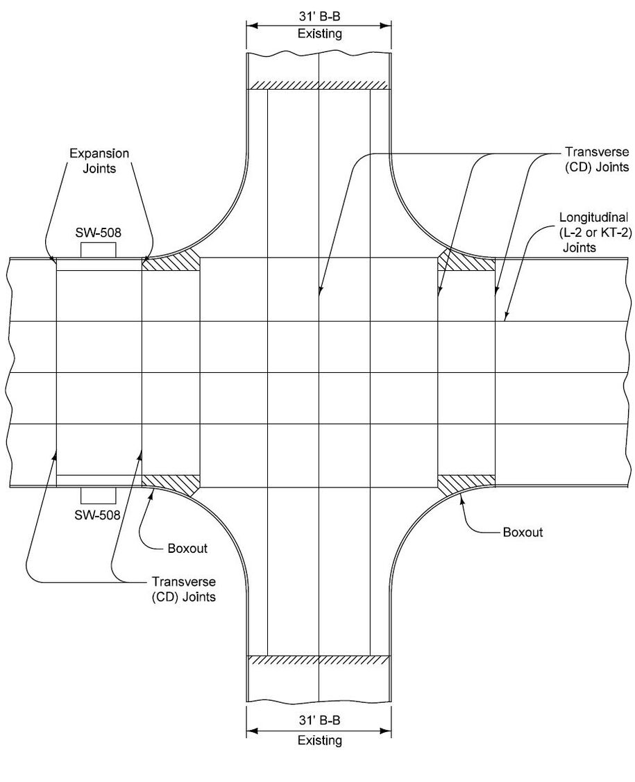
Figure 1: Placement of predetermined and difficult joints.
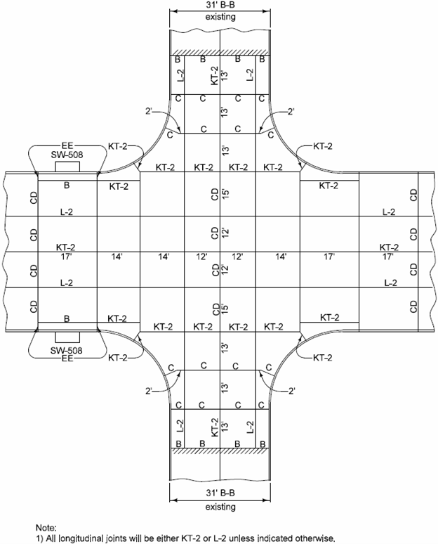
Figure 2: Final jointing layout.
Back to top