Content Information
On this page...
This section contains information pertinent to entrance and safety ramp pipe culverts, including pipe size and cover, plotting cross sections, and determining payment length.
Back to topPipe Size and Cover
For new entrances and safety ramps, pipes should be of adequate size to handle drainage. A 24 inch pipe is preferred, with 18 inches being the minimum diameter allowed on the NHS. Replacement pipes for reconstructed entrances and safety ramps should be the same size as existing pipes unless conditions have changed since installation or there is knowledge that the current pipe is too small.
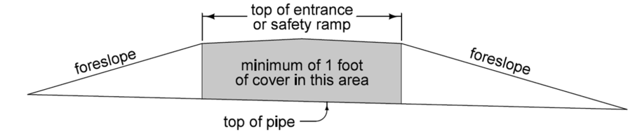
A minimum of 1 foot of cover should be placed over the top of the pipe, see Figure 1. If this is difficult to achieve, the pipe may be buried up to 6 inches; however, evaluation of the hydraulics must be considered to determine an appropriate pipe size given the reduced area.
Refer to DR-104 for depth of cover tables for concrete and corrugated pipes to determine if either type is acceptable with respect to the maximum allowable cover for each type. If the fill height exceeds the maximum allowable cover for a type of pipe, the designer must specify the culvert type in Tabulation 102-3. When determining maximum allowable cover for unclassified pipe, assume a concrete pipe.
Refer to Sections 2416, 2417 and 2422 of the Standard Specifications for more information regarding pipe installation
Back to topPlotting Cross Sections
Show entrances and safety ramp profiles on both the cross sections and plan and profile sheet. Plot cross sections of entrances and safety ramps, including the entrance and safety ramp pipes with aprons, in the cross sections. The cross sections should be plotted as seen from the roadway and should be drawn to the normal cross section scale. Refer to Section 1F-23 for guidance on entrance cross section sheeting and labeling requirements.
Back to topDetermining Payment Length
Several factors affect pipe length (which is used to determine payment length):
Top width (W):
For safety ramps, refer to Standard Road Plan EW-502.
For entrances, refer to Section 3K-2, Standard Road Plan EW-501, and the Iowa Primary Road Access Management Policy.
Foreslope at the pipe. As shown on EW-501 and EW-502, an 8:1 or flatter forslope is used with a pipe. For situations involving a steep ditch or roadway grade, 4% or more, the designer may want to adjust the foreslopes to reduce pipe length. Refer to Section 3F-3 for details pertaining to transverse foreslope adjustments.
Depth of fill over the pipe. Deeper fill means longer foreslopes, resulting in longer pipes.
Measurement is done between the intercepts of the top of the aprons with the foreslopes
Payment Length for RCP
When concrete pipe with concrete apron is specified, payment length is determined by first subtracting two times the distance C for the apron (refer to Standard Road Plan DR-201) from the measured length and then rounding up to the nearest two foot increment (concrete pipe is typically provided in two foot lengths).
Payment Length for CMP and Unclassified Pipe
When CMP or unclassified pipe is specified, payment length is determined by rounding the measured length up to the nearest foot (CMP is provided in one foot lengths).
Example 1
A 24 inch RCP is being placed under a 30 foot entrance which has 9 feet of fill over the top of the pipe and foreslopes of 8:1 at the pipe (see Figure 2). Determine the payment length if the ditch grade through the entrance is 2%.
Back to topExample 1
A 24 inch RCP is being placed under a 30 foot entrance which has 9 feet of fill over the top of the pipe and foreslopes of 8:1 at the pipe (see Figure 2). Determine the payment length if the ditch grade through the entrance is 2%.
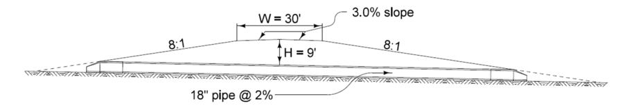
The measured length between the intercepts of the top of the aprons with the foreslopes is 171.21 feet. The C distance listed on DR-201 for a 24 inch pipe (assuming a Type 2 apron) is 2.50 feet (2’-6”). Payment length is determined by subtracting 2×C from the measured length (171.21’ – 2×2.50’ = 166.21 feet) and rounding up to the next 2 foot increment, resulting in a payment length of 168 feet.
Back to topExample 2
A 24 inch CMP is being placed under a 36 foot entrance which has six feet of fill over the top of the pipe (see Figure 3). The ditch grade is 6.5%. Determine the payment length if the ditch grade through the entrance is 6.5%.
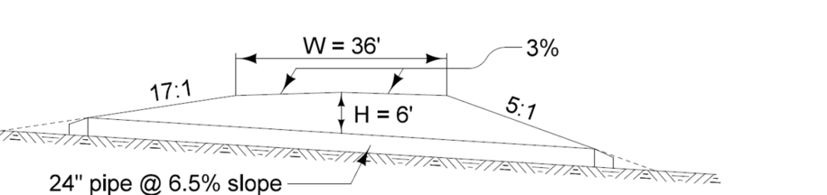
Since the ditch grade is 6.5% the foreslopes have been adjusted to 17:1 upstream and 5:1 downstream relative to a flat horizontal plane (see Section 3F-3). The measured length between the intercepts of the top of the aprons with the foreslopes is 119.82 feet. The measured length is then rounded up to the nearest one foot increment, resulting in a payment length of 120 feet.
Back to top