Content Information
On this page...
This section provides examples that demonstrate how to joint rural intersections by following the guidelines outlined in Section 7A-2.
Back to topExample 1 – T-Intersection (Painted Island)
This example demonstrates the jointing design process for a T-intersection of a rural two lane highway and a paved side road. The intersection has returns on each side (see Figure 1) and the pavement thickness is 10 inches. The design year truck volume on the side road is 250 vpd.
Step 1: Place Joints with Predetermined Locations
Longitudinal Joints
Because the location of longitudinal joints for both the mainline and the side road are predetermined by the lane pavement width, these joints should be placed first. Within the intersection, the road that is paved first determines which joints are longitudinal and which are transverse. In this example, assume that the mainline is paved first. Since the mainline is a rural two lane highway, the longitudinal joints are spaced at the lane pavement width of 12 feet.
To determine an appropriate longitudinal joint to use, refer to Standard Road Plan PV-101 or Table 2 in Section 7A-2. Normally, the type of joint used depends on the pavement thickness. Since the pavement thickness is greater than 8 inches in this case, either a KT-2 or an L-2 joint is appropriate.
Initial Transverse Joints
The longitudinal joints running down the centerline and edges of the side road define the locations of the first transverse joints for the mainline (see Figure 1). The only other joints with predetermined locations are the transverse joints that are placed where the end-of-taper sections terminate. End-of-taper sections are 2 foot wide sections placed at the ends of an intersection return (see Figure 1). They are used to prevent the return from narrowing to a point as it intersects with the pavement.
As Figure 1 shows, normal practice is to place a transverse joint in the mainline or side road pavement where the end-of-taper section terminates. Standard Road Plan PV-101 and Table 1 in Section 7A-2 indicate that a CD joint should be used on the mainline since the pavement thickness is greater than 8 inches. On the side road, CD joints are also used since the design year truck volume is greater than 200 vpd (C joints could be used on the side road if the design year truck volume was less than 200 vpd).
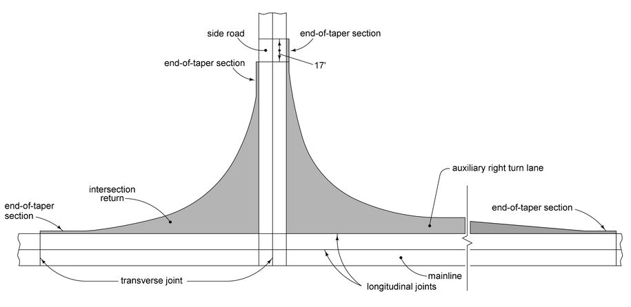
Figure 1: Placement of predetermined joints.
Step 2: Place Remaining Joints
The remaining joints (generally transverse joints) are placed in appropriate locations. As noted in Step 1, the appropriate transverse joint for both the mainline and the side road is the CD joint. The maximum spacing for CD joints is 17 feet and the minimum spacing is 12 feet. Therefore, the remaining areas that need transverse joints should have CD joints spaced within this range.
Mainline and Side Road
The placement of the remaining transverse joints on the mainline and side road is largely determined by the location of joints already placed in Steps 1 and 2 (see Figure 1). The remaining joints are spaced between 12 and 17 feet between these already-placed joints. However, the designer must also consider how these joints will be extended into the returns (described below).
Intersection Returns
After the transverse joints have been placed in the mainline and the side road, they are extended into the intersection returns to be used as transverse joints for those areas as well. As with other transverse joints, those in intersection returns must intersect with the free edge of the pavement. However, the acute angle between the joint and the pavement edge (and between the joint and other joints) must be greater than or equal to 70 degrees. Details A, and B in Figure 2 illustrate how to intersect joints with the free edge of the pavement (and with other joints) under various conditions.
Detail A shows a transverse joint that intersects with the free edge of the pavement unaltered. This is acceptable because all angles between the transverse joint and the longitudinal joints and between the transverse joint and the free edge of the pavement are greater than 70 degrees.
Detail B uses a dashed line to show the original position of a transverse joint whose angle with the free edge of the pavement is less than 70 degrees. This joint should be skewed to make it perpendicular to the free edge of the pavement, as shown by the solid line. However, skewing the joint to make it perpendicular to the free edge of the pavement causes the angle between the transverse joint and the longitudinal mainline joint to be less than 70 degrees. To resolve this situation, the transverse joint is extended a minimum of 2 feet beyond the mainline longitudinal joint, and then it is skewed to make it perpendicular to the free edge of the pavement.
After all joints are placed, the layout should be checked to ensure that all joint spacings and angles are acceptable. If they are not, the spacing of the mainline or side road joints may need to be changed, one or more joints may need to be added, or joints within the returns may need to be modified.
Figure 2 shows all the transverse joints appropriately placed.
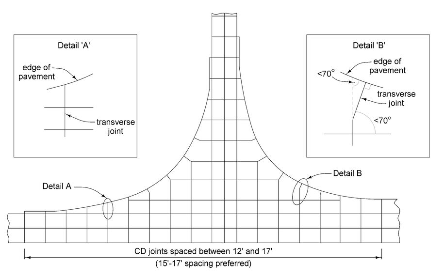
Figure 2: Placement of remaining joints.
Step 3: Label Joints
The completed jointing layout of the T-intersection is shown in Figure 3. As stated on Standard Road Plan PV-101, the L-2 and KT-2 joints may be used interchangeably, at the contractor’s discretion, depending on the paving sequence. Therefore, the designer may identify the longitudinal joints as either L-2 or KT-2 on the jointing layout. The transverse joints in the end-of-taper sections are C joints because they are only 2 feet long – not long enough to use a doweled transverse joint like the CD. The joints on the right side of the traffic island are also C joints as specified on Standard Road Plan PV-20.
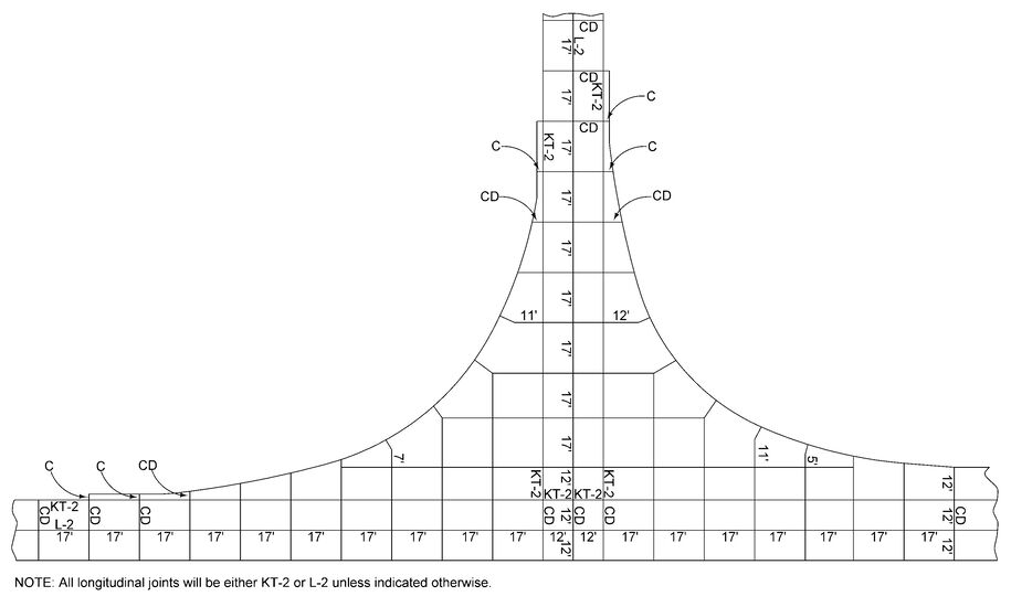
Figure 3: Final jointing layout.
Not every joint on the jointing layout needs to be identified. A few key joints on the diagram should be identified, and whenever a series of joints changes to a different type of joint, the joint at the location of the change should be identified. Also, any joint that may be a source of confusion should be identified.
Joint lengths are also shown on the jointing layout, normally rounded to the nearest foot. Similar to labeling joint types, not every length needs to be indicated. However, any length that cannot be inferred from the diagram should be labeled. For example, the distance the mainline or side road transverse joints extend into the intersection returns before being skewed perpendicular to the free edge of the pavement should be dimensioned (see Figure 3).
Back to topExample 2 – T-Intersection (Raised Island)
This example demonstrates the jointing design process for a T-intersection of a rural two-lane highway and a paved side road. The intersection has returns on each side (see Figure 1) and the pavement thickness is 10 inches. The design year truck volume on the side road is 250 vpd.
Step 1: Place Joints with Predetermined Locations
Longitudinal Joints
Because the location of longitudinal joints for both the mainline and the side road are predetermined by the lane pavement width, these joints should be placed first. Within the intersection, the road that is paved first determines which joints are longitudinal and which are transverse. In this example, assume that the mainline is paved first. Since the mainline is a rural two-lane highway, the longitudinal joints are spaced at the lane pavement width of 12 feet.
To determine an appropriate longitudinal joint to use, refer to Standard Road Plan PV-101 or Table 2 in Section 7A-2. Normally, the type of joint used depends on the pavement thickness. Since the pavement thickness is greater than 8 inches in this case, either a KT-2 or an L-2 joint is appropriate.
Initial Transverse Joints
The longitudinal joints running down the centerline and edges of the side road define the locations of the first transverse joints for the mainline (see Figure 1). The only other joints with predetermined locations are the transverse joints that are placed where the end-of-taper sections terminate. End-of-taper sections are 2 foot wide sections placed at the ends of an intersection return (see Figure 1). They are used to prevent the return from narrowing to a point as it intersects with the pavement.
As Figure 1 shows, normal practice is to place a transverse joint in the mainline or side road pavement where the end-of-taper section terminates. Standard Road Plan PV-101 and Table 1 in Section 7A-2 indicate that a CD joint should be used on the mainline since the pavement thickness is greater than 8 inches. On the side road, CD joints are also used since the design year truck volume is greater than 200 vpd (C joints could be used on the side road if the design year truck volume was less than 200 vpd).
Note that the transverse joints within the intersection are not skewed.
Step 2: Place Difficult Joints
Difficult locations to joint, such as intersection returns and traffic islands, are addressed next. After joints have been placed in these locations, the rest of the joints can be worked in around them.
Intersection Returns
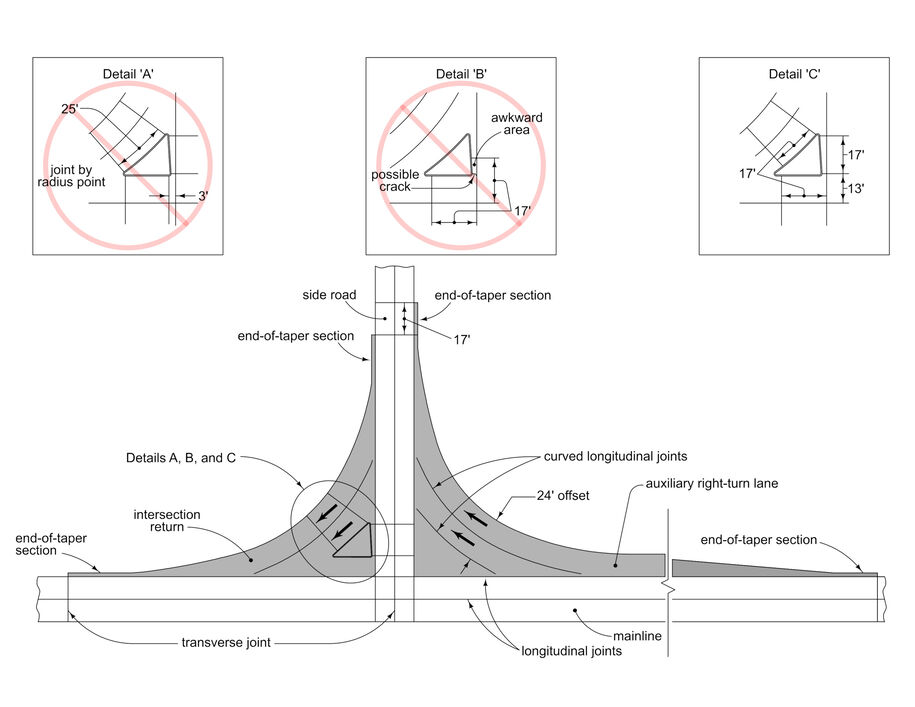
The two intersection returns are shaded in Figure 1. To help vehicles negotiate the turn, a curved longitudinal joint (normally offset 12 feet from the free edge of the pavement) is placed in the intersection return to delineate the turning path. A second curved longitudinal joint (normally offset 24 feet from the free edge of the pavement) is placed if enough area is available.
Traffic Islands
Joint design at the traffic islands is not an exact process. It is done by trial-and-error until satisfactory results are achieved.
The first thought may be to place CD transverse joints at every radius point of the island (see Detail A, Figure 1). However, with this layout the 20-foot maximum and 12-foot minimum spacings for a CD joint are violated.
Detail B shows joints at the desired 20-foot interval. Although the spacing of this placement is correct, an awkward area of pavement is formed and a crack is likely to develop as shown in Detail B.
Detail C illustrates a combination of the methods used in the first two details. No rules of spacing are violated and no awkward areas of pavement exist.
The transverse joints attached to the island are extended across the side road and mainline pavements and across the intersection return adjacent to the island, as shown in Figure 1. The joints used in one area must also be acceptable for any other areas into which they are extended. If the extended joints do not satisfy spacing or other criteria in any adjacent areas, they must be redesigned in the original area.
Step 3: Place Remaining Joints
After the joints at difficult locations are placed, the remaining joints (generally transverse joints) are placed in appropriate locations. As noted in Step 1, the appropriate transverse joint for both the mainline and the side road is the CD joint. The maximum spacing for CD joints is 20 feet and the minimum spacing is 12 feet. Therefore, the remaining areas that need transverse joints should have CD joints spaced within this range.
Mainline and Side Road
The placement of the remaining transverse joints on the mainline and side road is largely determined by the location of joints already placed in Steps 1 and 2 (see Figure 1). The remaining joints are spaced between 12 and 20 feet between these already-placed joints. However, the designer must also consider how these joints will be extended into the returns (described below).
Intersection Returns
After the transverse joints have been placed in the mainline and the side road, they are extended into the intersection returns to be used as transverse joints for those areas as well. As with other transverse joints, those in intersection returns must intersect with the free edge of the pavement. However, the acute angle between the joint and the pavement edge (and between the joint and other joints) must be greater than or equal to 70 degrees. Details A, B, C, and D in Figure 2 illustrate how to intersect joints with the free edge of the pavement (and with other joints) under various conditions.
Detail A shows a transverse joint that intersects with the free edge of the pavement unaltered. This is acceptable because all angles between the transverse joint and the longitudinal joints and between the transverse joint and the free edge of the pavement are greater than 70 degrees.
Detail B uses a dashed line to show the original position of a transverse joint whose angle with the free edge of the pavement is less than 70 degrees. This joint should be skewed to make it perpendicular to the free edge of the pavement, as shown by the solid line.
Detail C illustrates a situation where skewing the joint to make it perpendicular to the free edge of the pavement causes the angle between the joint and the edge of the mainline to be less than 70 degrees. When this situation occurs, the joint is extended a minimum of 2 feet beyond the edge of the mainline or side road, and then it is skewed to make it perpendicular to the free edge of the pavement.
Detail D shows the curved longitudinal joints that were placed in the intersection return in Step 2. Each of these joints terminates at an intersection with a transverse joint. The intersection of these joints is required to be at least 2 feet from the edge of the mainline or side road. This requirement determines the appropriate transverse joint at which the longitudinal joint terminates. The dashed line in the detail indicates the position of the longitudinal joint if it is extended too far. Because the intersection with the transverse joint is less than 2 feet from the pavement edge, the longitudinal joint is terminated at the previous transverse joint.
After all joints are placed, the layout should be checked to ensure that all joint spacings and angles are acceptable. If they are not, the spacing of the mainline or side road joints may need to be changed, one or more joints may need to be added, or joints within the returns may need to be modified.
Figure 2 shows all the transverse joints appropriately placed.
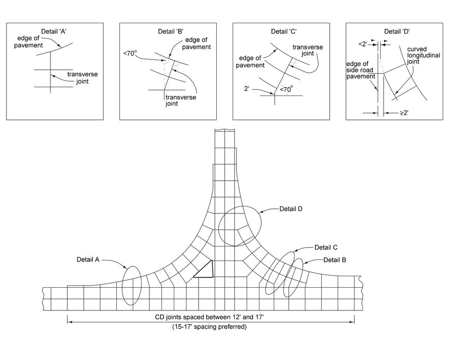
Figure 2: Placement of remaining joints.
Step 4: Label Joints
The completed jointing layout of the T-intersection is shown in Figure 3. As stated on Standard Road Plan PV-101, the L-2 and KT-2 joints may be used interchangeably, at the contractor’s discretion, depending on the paving sequence. Therefore, the designer may identify the longitudinal joints as either L-2 or KT-2 on the jointing layout. The transverse joints in the end-of-taper sections are C joints because they are only 2 feet long¾not long enough to use a doweled transverse joint like the CD. The joints on the right side of the traffic island are also C joints as specified on Standard Road Plan PV-20.
Not every joint on the jointing layout needs to be identified. A few key joints on the diagram should be identified, and whenever a series of joints changes to a different type of joint, the joint at the location of the change should be identified. Also, any joint that may be a source of confusion should be identified.
Joint lengths are also shown on the jointing layout, normally rounded to the nearest foot. Similar to labeling joint types, not every length needs to be indicated. However, any length that cannot be inferred from the diagram should be labeled. For example, the distance the mainline or side road transverse joints extend into the intersection returns before being skewed perpendicular to the free edge of the pavement should be dimensioned (see Figure 3).
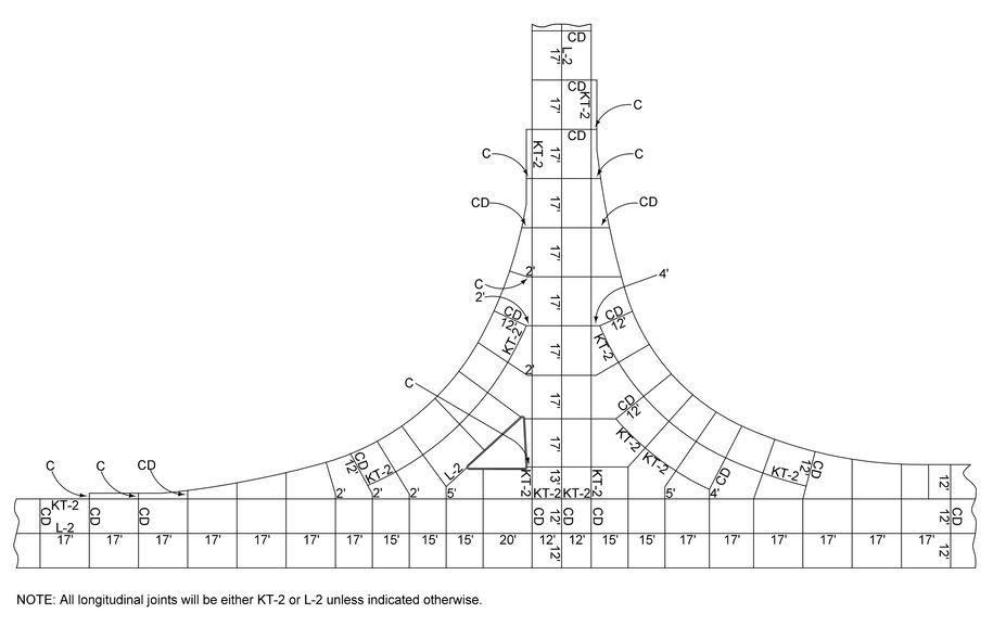
Figure 3: Final jointing layout.
Back to topExample 3 – Intersection at Divided Highway (Painted Islands)
This example demonstrates the jointing design process for a four-way intersection with painted islands at a divided highway. The process is basically the same as a T-intersection with painted islands, with the addition of a paved median opening to joint.
As with the T-intersection, start out by placing the longitudinal joints that are predetermined by the lane pavement width. After doing this, place longitudinal joints through the opening (see Figure 1). The edges of the left turn lanes define the location of two of these joints. The remaining longitudinal joints in the opening are spaced roughly a lane width apart – somewhere in the range of 10 to 16 feet is acceptable.
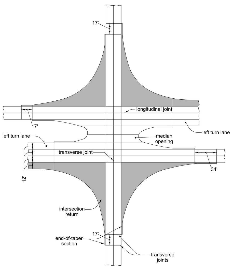
Figure 1: Placement of predetermined joints.
After this, the process is basically the same as the T-intersection:
Place the transverse joints at the end-of-taper sections.
Place the remaining transverse joints and extend them into the returns and into the median opening. Refer back to the T-intersection example for details on how the joints should intersect with the free edge of the pavement and with other joints.
Label the joints.
Figure 2 illustrates the final jointing layout.
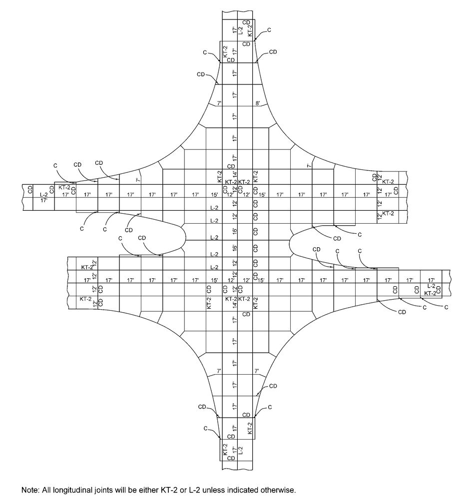
Figure 2: Final jointing layout
Back to topExample 4 – Intersection at Divided Highway (Raised Islands)
This example demonstrates the jointing design process for a four-way intersection with raised islands at a divided highway. The process is basically the same as a T-intersection with raised islands, with the addition of a paved median opening to joint.
As with the T-intersection, start out by placing the longitudinal joints that are predetermined by the lane pavement width. After doing this, place longitudinal joints through the opening (see Figure 1). The edges of the left-turn lanes define the location of two of these joints. The remaining longitudinal joints in the opening are spaced roughly a lane width apart—somewhere in the range of 10 to 16 feet is acceptable.
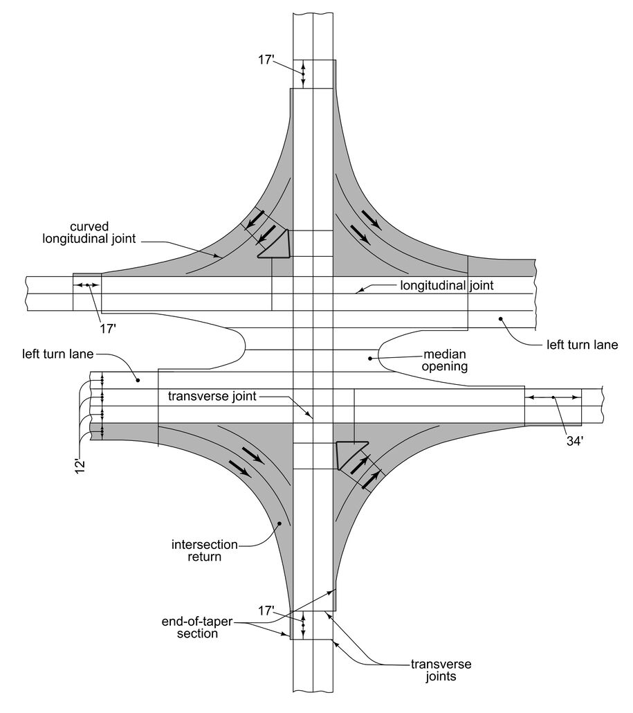
Figure 1: Placement of predetermined and difficult joints.
After this, the process is basically the same as the T-intersection:
Place the transverse joints at the end-of-taper sections.
Place the curved longitudinal joints in the return.
Place the transverse joints around the islands. Figure 1 illustrates the design through this point.
Place the remaining transverse joints and extend them into the returns and into the median opening. Refer back to the T-intersection example for details on how the joints should intersect with the free edge of the pavement and with other joints.
Label the joints.
Figure 2 illustrates the final jointing layout.
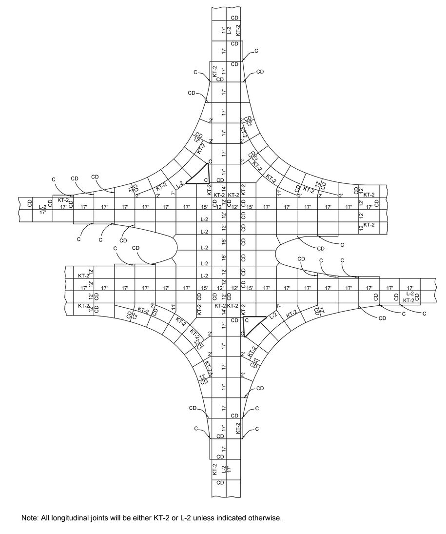
Figure 2: Final jointing layout.
Back to topExample 5 – Skewed Intersection (Painted Islands)
This example demonstrates the jointing design process for a skewed intersection with painted islands. The process is basically the same as a T-intersection with painted islands, except that the side road longitudinal jointing must be altered through the intersection to be perpendicular to the mainline.
As with the T-intersection, start out by placing the longitudinal joints that are predetermined by the lane pavement width. The side road longitudinal jointing through the intersection must be altered to be perpendicular to the mainline longitudinal jointing (see Figure 1).
After this, the process is basically the same as the T-intersection:
Place the transverse joints at the end-of-taper sections.
Place the remaining transverse joints and extend them into the returns and into the median opening. Refer back to the T-intersection example for details on how the joints should intersect with the free edge of the pavement and with other joints.
Label the joints.
Figure 2 illustrates the final jointing layout.
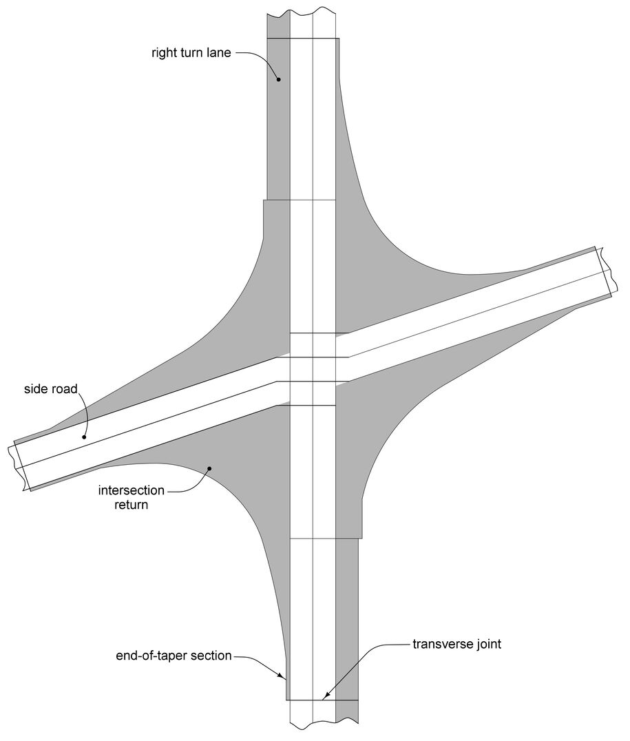
Figure 1: Placement of predetermined and difficult joints.
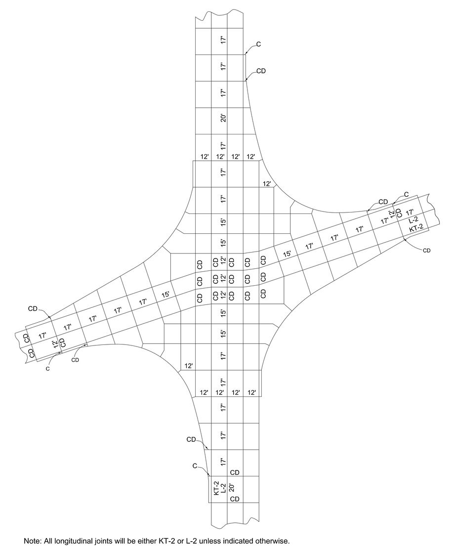
Figure 2: Final jointing layout.
Back to topExample 6 – Skewed Intersection (Raised Islands)
This example demonstrates the jointing design process for a skewed intersection with raised islands. The process is basically the same as a T-intersection with raised islands, except that the side road longitudinal jointing must be altered through the intersection to be perpendicular to the mainline.
As with the T-intersection, start out by placing the longitudinal joints that are predetermined by the lane pavement width. The side road longitudinal jointing through the intersection must be altered to be perpendicular to the mainline longitudinal jointing (see Figure 1).
After this, the process is basically the same as the T-intersection:
Place the transverse joints at the end-of-taper sections.
Place the curved longitudinal joints in the return.
Place the transverse joints around the islands. Figure 1 illustrates the design through this point.
Place the remaining transverse joints and extend them into the returns and into the median opening. Refer back to the T-intersection example for details on how the joints should intersect with the free edge of the pavement and with other joints.
Label the joints.
Figure 2 illustrates the final jointing layout.
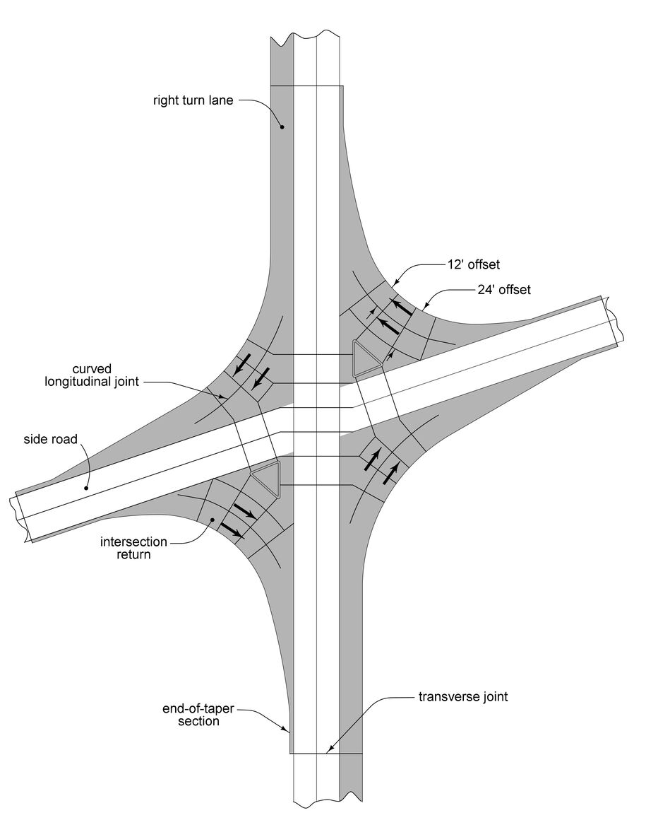
Figure 1: Placement of predetermined and difficult joints.
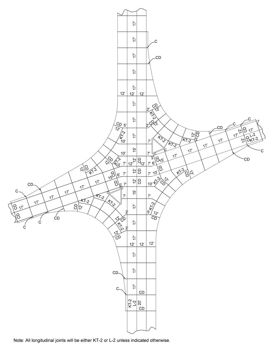
Figure 2: Final jointing layout.
Even though not all rural intersections will be exactly like the ones in these examples, the processes are applicable to other layouts.
Back to top