
Content Information
On this page...
The cross section of a roadway is made up of many parts. One of the key parts is the overall pavement section. This is most often made up of three layers: the driving surface (commonly called the pavement), the drainage layer, and the strength layer. The drainage layer serves as a path to get water out from under the driving surface. The strength layer transfers the load from the pavement to the road base. Sometimes the drainage and strength layers are combined into one layer, referred to as a common or combined layer, which serves both functions. Designers should check with the Pavement Design Engineer and the Soils Design Engineer to find out what layers are to be used on their project.
Back to top
Drainage Layer
The drainage layer includes a permeable granular layer and a subdrain. It provides a path for water to drain out from under the driving surface. The granular material allows water to pass through to the subdrain where it collects and outlets into a ditch, storm sewer, or similar feature.
The drainage layer is located immediately below the pavement. The two possible granular materials are Granular Subbase and Modified Subbase. Granular Subbase is typically used under PCC, and Modified Subbase is used under HMA or when the base needs to be driven on during staging and/or paving.
Back to topStrength Layer
The strength layer is a layer of material that transfers traffic loads from the driving surface to the base. It is located under the drainage layer. Select Backfill (good quality glacial clay and clean sand from on-site sources) is the most common material for the strength layer. When Select Backfill is not available, Special Backfill or Modified Subbase is used on the project.
The location of the strength layer depends on the material being used for that layer. Select Backfill is used below the top of subgrade, while Special Backfill and Modified Subbase are used above the subgrade. When Modified Subbase is used as the strength layer, drainage needs to be provided, typically by including longitudinal subdrains. When Special Backfill is used as the strength layer, designers may need to account for drainage with subdrains or as shown in Grading Typical G_4D_Grade_Delay_S.
Occasionally, polymer grid is used for additional strength. When used, polymer grid is located immediately above the soil subgrade. Include in the details, similar to Figure 1. Coordinate with Soils Design Engineer and Pavement Design Engineer for details of polymer grid placement.
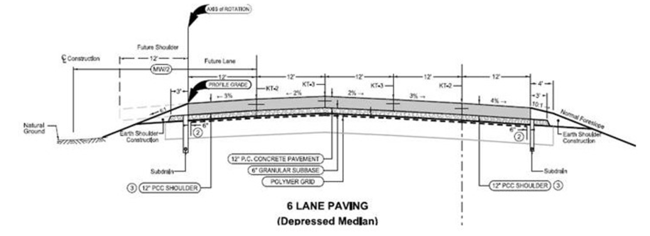
Figure 1: Detail showing polymer grid placement.
Back to topCommon or Combined Layer
A common or combined layer is a layer of material that serves the dual purpose of being a drainage layer and a strength layer. It provides a path for water to drain to the subdrain and transfers the traffic loads to the base. It consists of Modified Subbase and may be used when Select Backfill is not available. The common or combined layer is located above the subgrade.
Back to topLayer Widths
Layer widths are related to pavement type. For PCC pavement, a 3 foot wide pad of granular material is needed for the paving machine to run on. Strength and drainage layers must extend at least 3 feet beyond the edge of mainline pavement when PCC is called for. This is reflected in the shoulder typical components. For full depth PCC shoulders, with or without curb, the strength and drainage layers must extend at least 3 feet beyond the edge of the shoulder pavement as shown in the full depth PCC shoulder typical components. Paved shoulder alternates typicals show the strength and drainage layers extending 1 foot beyond the edge of the shoulder – this is what designers base their bids on. PCC paving contractors are responsible for furnishing and placing the additional 2 feet needed for the paving machine.
Back to topModifying Typical Cross Sections
Typical cross sections show the most common case for each roadway type. For ramp, two lane, four lane, and six lane rural typical cross sections, a drainage layer is shown and Select Backfill is assumed to be used as the strength layer. For the six lane urban typical cross section, a drainage layer and a strength layer are shown above the subgrade. Any cases other than those listed will require the typical cross sections to be modified.
Modifications for Drainage and Strength Layer above the Subgrade
Back to topBackbone
- Copy the top of subgrade line down 36 feet.
- Move labels down and add or copy a label for the strength layer.
- Pattern the strength layer with the appropriate pattern found in dsnMethods.cel.
The end result should look similar to the modified backbone in Figure 2.
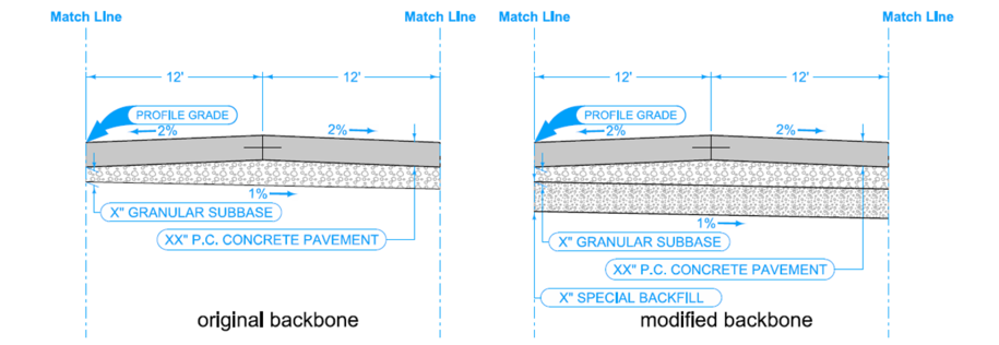
Figure 2: Modifying a backbone strength layer.
Back to topShoulder
- Copy the top of subgrade line down the same distance as the backbone.
- Extend the top of subgrade and foreslope lines to meet.
- Extend top line of the strength layer to two feet beyond the edge of shoulder.
- Dimension the two feet by copying one of the other dimensions and using the modify element tool to attach it to the correct points.
- Adjust labels so they are not covering part of the drawing.
The end result should look similar to the modified shoulder in Figure 3.
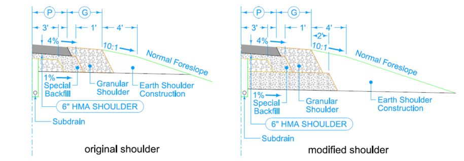
Figure 3: Modifying a shoulder backbone strength layer.
Back to topModifications for a Common or Combined Layer
Backbone
Change the subbase label to read X” MODIFIED SUBBASE. The end result should look similar to the modified backbone in Figure 4.
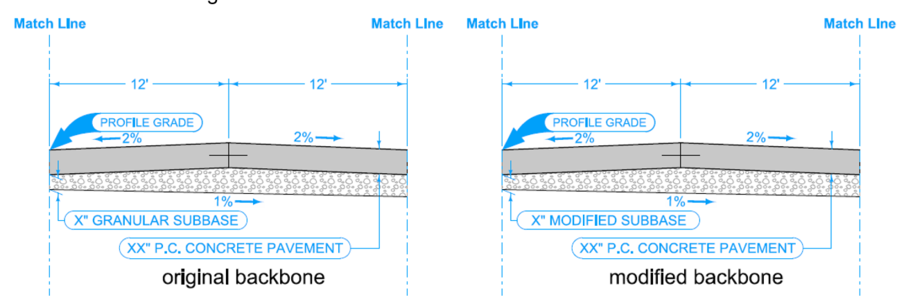
Figure 4: Modifying a backbone strength layer
Back to topShoulder
- Extend top line of the combined layer to one foot beyond the edge of shoulder.
- Change the Special Backfill to Modified Subbase.
- Adjust labels to point to the correct locations.
- Dimension the one foot by copying one of the other dimensions and using the modify element tool to attach the leaders to the correct points.
The end result should look similar to the modified shoulder in Figure 5.
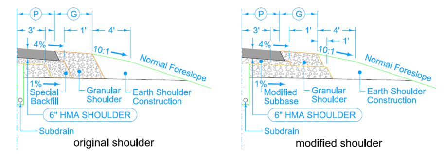
Figure 5: Modifying a shoulder backbone strength layer.
Back to top