Content Information
On this page...
Background
NPDES General Permit No. 2 Part IV, D, 2, A.(2).(a), which applies to disturbed areas of 10 acres or more, states a requirement of a temporary sediment basin providing 3600 ft3 of storm water storage per disturbed acre drained. If right of way or other constraints prohibit constructing a temporary sediment basin that meets this requirement, other temporary sediment control devices must be used. The permit does not state a minimum storage requirement if equivalent temporary sediment control devices other than a temporary sediment basin are used; however, designers should use 3600 ft3 of storm water storage per acre as a goal.
NPDES General Permit No. 2 Part IV, D, 2, A.(2).(b), which applies to disturbed areas of less than 10 acres, requires the use of either sediment control devices, or a temporary sediment basin providing 3600 ft3 of storm water storage per disturbed acre drained. The permit does not state a minimum storage requirement if equivalent temporary sediment control devices other than a temporary sediment basin are used; however, designers should use 3600 ft3 of storm water storage per acre as a goal.
If a project involves curb and gutter with storm sewer (typically urban projects), a goal of 3600 ft3 of storage per disturbed acre drained may not be attainable. For a 3R project, a goal of 3600 ft3 of storage per disturbed acre drained may not be necessary if vegetative buffers are used. In these cases, other methods such as those discussed in Sections 10C-3, 10C-4, and 10C-5 may be used. Contact the Agronomist if required storage volume cannot be met or vegetated buffers are being considered.
Back to topDetermining Storm Water Detention Need
Designers need to determine the number of disturbed acres for each drainage basin. Disturbed areas are areas where vegetation, rocks, pavement and other protective ground covers are removed during construction resulting in the exposure of underlying soil. Examples of soil disturbing activities include clearing and grubbing, grading or excavating (i.e. cutting, filling, trenching), stockpiling of soils, demolition, etc. A drainage basin is an area that drains to a common point where it exits the right of way. For each drainage basin, 3600 ft3 of storm water storage per acre of disturbed area is required.

| In the plans, include color plan sheets that delineate the drainage basins. |
|---|
Storm water detention need is simply the number of disturbed acres drained multiplied by 3600 ft3. Thus, two acres of disturbed area requires 3600 × 2 = 7200 ft3 of detention, 3.5 acres of disturbed area requires 3600 × 3.5 = 12,600 ft3, etc.
Tabulation 100-34 is used to tabulate the volume of storm water detention required for each drainage basin.
Back to topDetermining Storm Water Detention Provided
Storm water detention provided for a drainage basin includes the total volume of storage provided by all temporary sediment control devices in that basin. A combination of devices might be required, or just one type may be all that is needed. Regardless of the devices used, storm water detention provided for a drainage basin should exceed what is needed.
Tabulation 100-34 is used to tabulate total storm water volumes required and provided. Tabulations 100-18, 100-14, 100-32, and 100-33 are used to tabulate storage volumes for each of the temporary sediment control devices. Use final ditch grades (or as-built ditch grades if using existing ditches) when filling in these tabs. In areas where ditch grade varies between devices, designers will need to determine an average percent slope.
Back to topTemporary Sediment Control Devices for Storm Water Detention
Temporary sediment control devices used for storm water detention include Silt Fence Ditch Checks (EC-201), Rock Check Dams (EC-302), Temporary Sediment Control Basins (EC-601), Silt Basins (EW-403), and Slash Mulch Berms (570-1). These devices detain storm water, which allows sediment to settle out. See Section 10C-1 for information regarding these devices, including how they are bid.
Silt Fence for Ditch Check (EC-201)
Silt fence ditch checks are the most common temporary sediment control device used for storm water detention. Use these unless directed otherwise.
Shallow ditch installations are used in ditches shallower than 19 inches. No ditch installations are used in areas without a backslope.
Rock Check Dam (EC-302)
Occasionally, a few silt fence ditch checks will fail and need to be replaced with rock check dams. A quantity of rock check dam based on a percentage of silt fence ditch check is included in the plans, see Section 10C-1.
At times, the Roadside Development Section will call for rock check dams rather than silt fence ditch checks. When rock check dams are called for in the plans, refer to Table 3 of Section 10C-1 for spacing requirements. Verify they will be located outside of the construction clear zone.
Temporary Sediment Control Basin (EC-601)
Temporary sediment control basins are placed at the point where storm water runoff leaves the right of way. They are required for disturbed areas of 10 acres or more. They are optional for disturbed areas less than 10 acres.
Silt Basin (EW-403)
Silt basins are most commonly used in ditches upstream of culverts to intercept storm water and allow sediment to settle out. They may also be used when silt fence ditch checks or rock check dams don’t provide adequate storage. Silt ditches and silt dikes may be used in shallow ditch and/or no ditch areas where adequate storage cannot be achieved using Detail 570-4.
Slash Mulch Berm (570-1)
Slash mulch berms are used as an alternative to silt fence for ditch check.
|
| Include slash mulch berms in the plans only if requested by Roadside Development Section. |
|---|
Tabulations
Calculating storm water volume involves several tabulations typically filled out in the following order:
Stormwater Drainage Basin and Storage (Tabulation 100-34)
Silt Fence for Ditch Checks (Tabulation 100-18)
Rock Check Dams (Tabulation 100-32)
Silt Basins (Tabulation 100-14)
Temporary Sediment Control Basins (Tabulation 100-33)
Not all types of storm water storage devices will be needed for each project, so which tabs to include will vary from project to project. However, Tabulation 100-34 is required on all projects involving storm water detention.
Note: Storm water tabs should be filled out prior to D5 because some projects may require more detention than can be provided by the control devices referenced above. This may result in the need for additional right-of-way or easement.
Stormwater Drainage Basin and Storage (100-34)
This tab requires designers to determine the total disturbed area for each drainage basin. A drainage basin is an area that drains to a common point where storm water leaves the right-of-way. As explained in Section 10C-1, disturbed areas are areas where vegetation, rocks, pavement and other protective ground covers are removed during construction resulting in the exposure of underlying soil. Once this has been determined for a drainage basin, this is entered into Tabulation 100-34.
Some (or all) of the drainage basin may not provide areas for storage. This is entered into the Disturbed Area without Storage Provided column. The remainder is entered into the Disturbed Area with Storage Provided Column, which is used to determine Total Storage Volume Required. As noted at the start of this section, 3600 ft3 of storage is required per acre of disturbed area where the storage can be provided, so the formula for determining required storage volume for a drainage basin is:
Total Storage Volume Required (ft3) = Disturbed Area with Storage Provided (acres) × 3600
The Disturbed Area without Storage Provided is not included in the Total Storage Volume Required.
Tabulation 100-34 is also where storm water detention devices (best management practices) are listed, and where total storage volume provided for each best management practice is calculated for each drainage basin. For areas without storage provided, the best management practices are listed, but no storage calculations are provided.
Silt Fence for Ditch Checks (100-18)
The storm water detention volume calculation for each device is based on using the average of the upstream end area and the downstream end area, and the spacing between the upstream and downstream devices.
Storm water volume = ½ (upstream end area + downstream end area) × spacing
Ditch foreslope, backslope, and width are required to calculate end areas, see Figure 1.
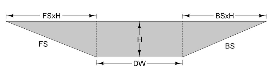
Figure 1: End area for a temporary sediment control device. FS = ditch foreslope, BS = ditch backslope, DW = ditch width, and H = device height.
The end area consists of two triangular components and one rectangular component. The formula is:
End area = ½ × H × H × FS + DW × H + ½ × H × H × BS
= ½ × H2 × FS + DW × H + ½ × H2 × BS
Refer to Table 2 of Section 10C-1 for spacing requirements. These were calculated such that the top of the downstream device is at approximately the same elevation as the bottom of the upstream device.
The height of silt fence is 19 inches (1.58 feet). Silt fence tends to droop between posts, so storage volume is calculated using a 15% reduction in the height of the device. For silt fence ditch checks, this results in a functional height, H, of 0.85×1.58 feet = 1.343 feet. With the 15% reduction in height, the upstream end area is always zero and the ponded length is less than the spacing, see Figure 2.
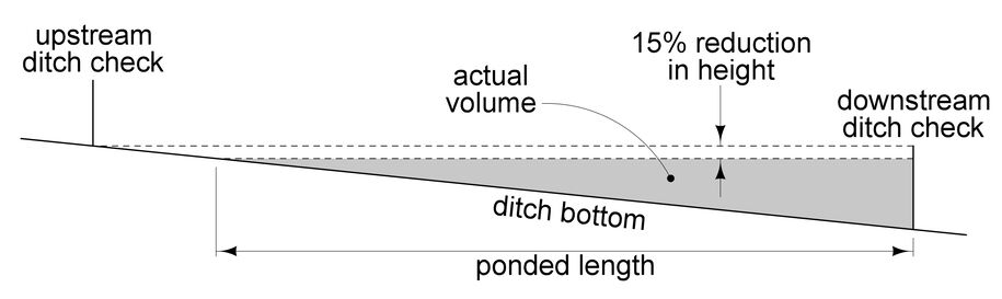
Figure 2: 15% reduction in height reduces upstream end area to zero.
Rather than calculating the ponded length, the device spacing is used to simplify calculations, see Figure 3.
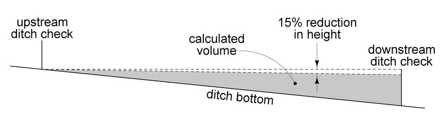
Figure 3: Calculating storage volume.
This simplifies the formula for storm water volume to:
Storm water volume = ½ × spacing × (½ × H2 × FS + DW × H + ½ × H2 × BS)
This is the formula the calc files use to calculate storage volume for each silt fence ditch check. The formula slightly over calculates storage volume, but the assumed 15% reduction in height results in storage volume calculations that are still somewhat conservative.
|
| If an Avg. % Slope of 6% or greater is entered into the calc file, it will produce a value of XX for Spacing. Contact the Roadside Development Section in the Office of Design for guidance. Rock check dams may be required. If the Roadside Development Section approves the use of silt fence ditch check, simply type in a value for Spacing to override the code. |
|---|
Refer to Section 10C-1 for determining maintenance and removal quantities.
Rock Check Dam (100-32)
Storm water volume calculations are done in the same manner as for Silt Fence for Ditch Check. Similar to silt fence ditch checks, the top of rock check dams generally won’t be perfectly level. To account for this, storage volume is calculated using a 10% reduction in the height of the device. This results in a functional height, H, of 1.8 feet used for storage volume calculations. This reduces the upstream end area to zero, so the same storage volume formula for silt fence ditch checks is used for rock check dams:
Storm water volume = ½ × spacing × (½ × H2 × FS + DW × H + ½ × H2 × BS)
Similar to silt fence ditch checks, the formula slightly over calculates storage volume, but the assumed 10% reduction in height results in storage volume calculations that are still somewhat conservative.
Refer to Table 3 in Section 10C-1 for spacing requirements. Like silt fence ditch checks, these were calculated such that the top of the downstream device is at approximately the same elevation as the bottom of the upstream device.
|
| Calculate storm water volume only for rock check dams that are called out by the Roadside Development Section for use as storm water detention devices. Do not calculate storm water volume for rock check dams included as replacement for silt fence ditch checks. |
|---|
Refer to Section 10C-1 for determining maintenance and removal quantities.
Tabulation of Silt Basins (100-14)
Silt basins differ from silt fence ditch checks and rock check dams in that they typically aren’t placed in a series; rather, they are typically placed in particular locations such as upstream of culverts. As such, storage volume isn’t based on spacing, but on the 50 foot length shown on EW-403. Also, silt basins are excavated into the ditch, so the sides of the basin are approximately vertical. For calculation purposes, they assumed to be vertical. Similar to rock check dams, the top of silt basins generally won’t be perfectly level. To account for this, storage volume is calculated using a 5% reduction in the height of the device. This results in a functional height, H, of 2.85 feet used for storage volume calculations. The resulting equation for determining storage volume is:
Storm water volume = ½ × Length × (upstream end area + downstream end area)
= ½ × Length × [Width × Height + Width × (Height - Length × Avg.%Slope)]
where:
Width = basin width, typically 10 feet
Height = basin height, functional height of 2.85 feet is used
Length = basin length, typically 50 feet
Avg.%Slope = average ditch slope
If the average ditch slope is such that Height - Length × Avg.%Slope ≤ 0, this term is dropped from the equation)
Refer to Section 10C-1 for determining maintenance and removal quantities.
Temporary Sediment Control Basin (100-33)
The storm water detention volume calculation for temporary sediment control basins is similar to silt fence ditch checks and rock check dams. The effective height is taken to be the top of the vertical pipe relative to the ditch grade (rather than the basin bottom), which equates to 2.5 feet. As a result of construction and/or settlement, the top of the vertical pipe in temporary sediment control basins may be somewhat lower than 2.5 feet above ditch grade. To account for this, storage volume is calculated using a 5% reduction in the height of the top of the vertical pipe. This results in a functional height, H, of 2.375 feet used for storage volume calculations. Like silt fence ditch checks and rock check dams, the upstream end area is zero. Unlike silt fence ditch checks and rock check dams, there are no spacing requirements upon which to base volume calculations. Therefore, volume calculations are based on the ponded length.
Storm water volume = ½ × (½ × FS × H2 + DW × H + ½ × BS × H2) × ponded length
Ponded length is calculated by dividing the functional height of the device by the average ditch slope, see Figure 4.
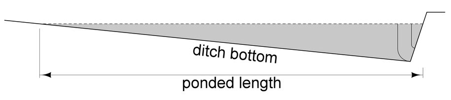
Figure 4: Calculating ponded length.
The resulting equation for determining storage volume is:
Storm water volume = (¼ × FS × H2 + ½ × DW × H + ¼ × BS × H2) ×
Refer to Section 10C-1 for determining maintenance and removal quantities.
Back to topStorm Water Detention in Shallow or No Ditch Situations
Occasionally, designers run into situations requiring storm water detention in shallow ditch or no ditch areas. A shallow ditch is defined as a ditch less than 19 inches deep. Silt fence is installed at a height of 19 inches, so if a ditch is less than 19 inches deep, storm water can potentially pond deep enough to run around a silt fence ditch check rather than being captured.
A no ditch situation is defined as an area with no backslope (at least within the right-of-way).
Back to topShallow Ditch
As shown in Standard Road Plan EC-201, silt fence is placed transverse to the foreslope, and then hooked to parallel the ditch. Tabulation 100-18 is used to tab the silt fence. This is tabbed as a Type 4 installation.
Figure 5 shows the end area associated with a shallow ditch installation. The parallel run of silt fence is located several feet behind the breakover for the backslope. This creates a small rectangular area. To simplify calculations, part of this rectangular area is ignored. The result is an end area the same as is used for a normal silt fence ditch check installation, thus the same equation is used.
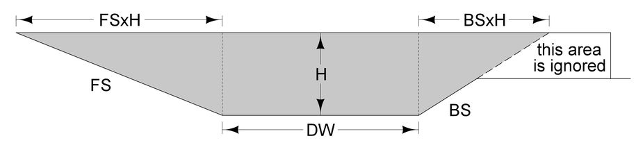
Figure 5: End area for shallow ditch.
Unlike standard ditches, the bottom of a shallow ditch may be less than 10 feet wide. In some situations (for example, a temporary runaround), the ditch may be a V ditch. In a case such as this, enter a value of 0 for DW.
Back to topNo Ditch
As shown in Standard Road Plan EC-201, silt fence is placed transverse to the foreslope, and then hooked to parallel the toe of foreslope. Tabulation 100-18 is used to tab the silt fence. This is tabbed as a Type 5 installation.
Figure 6 shows the end area associated with a no ditch installation. The parallel run of silt fence acts as a backslope. The end area is essentially the same as is used for a normal silt fence ditch check; however, the backslope is 0. The installation extends about 14 feet beyond the toe of the foreslope. To be conservative, use 13 feet for DW. This will also account for situations when the ground beyond the toe of foreslope continues to slope away, which would slightly decrease storage volume.
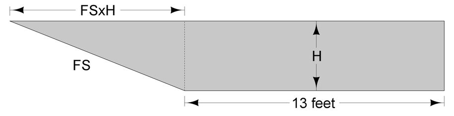
Figure 6: End area for no ditch.
For both shallow ditch and no ditch situations, if the ditch grade (shallow ditch situations) or grade along the toe of foreslope (no ditch situations) is less than 0.5%, place a run of silt fence 5 feet parallel to the shallow or no ditch installation to capture stormwater that could run around the end of the installation. An additional run of silt fence is always placed at the right-of-way line.
Standard Road Plan EW-403, Temporary Erosion Control Measures, may also be used in some no ditch situations if silt fence ditch checks don’t provide adequate storage.
Back to top
Example – Tabulating Storm Water Storage
The following example demonstrates the process for filling out the storm water tabs. The example is a grading project.
The tabs are presented in the order they are typically filled out. Because Tabulation 100-34 lists the storage devices (best management practices) used, it is filled out as the other tabs are filled out. For storm water detention devices, start with silt fence ditch checks to see if they will hold the required storage. Other devices such as rock check dams, silt basins, or temporary sediment control basins can be added if silt fence ditch checks are not sufficient to contain the required storage.
Filling in Tabulation 100-34, Stormwater Drainage Basin and Storage
First determine the acres of disturbed area for a drainage basin. A drainage basin is defined as an area of land where surface water converges to a single point at a lower elevation and exits the right-of-way. A disturbed area is where vegetation, rocks, pavement and other protective ground covers are removed resulting in the exposure of underlying soil. Flood the disturbed area to determine the acreage.
This project involves seven drainage basins. Each of the drainage basins consists entirely of disturbed area, and each provides areas for storm water detention. Below is the color plan sheet included in the plans.
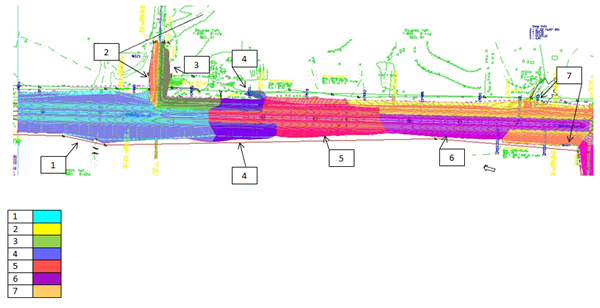
Once the acres of disturbed area are determined for a drainage basin, the Total Disturbed Area, Disturbed Area with Storage Provided, and Disturbed Area without Storage Provided columns in Tabulation 100-34 can be filled out. The Disturbed Area with Storage Provided is used to self-calculate the Total Storage Volume Required for that drainage basin. Label each drainage basin and the disturbed area in acres. Stationing for basins starting and ending points, as well as discharge points, will need to be labeled. The figure below shows the above mentioned columns in Tabulation 100-34 filled out for Basin No. 1.

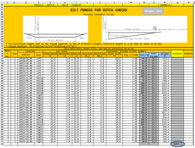
Filling in Tabulation 100-18, Silt Fences for Ditch Checks
For silt fence ditch checks, the foreslope, backslope, ditch width, and average percent slope between devices need to be filled in for the volume to self-calculate. The Spacing column will auto fill when the Avg. % slope field is filled. The drainage basin number is required to be filled in for the volume calculation to work. The figure below shows Tabulation 100-18 filled out for Basin No. 1.
In Tabulation 100-34, choose the Silt Fences for Ditch Checks (EC-201) option from the pull down menu in the Best Management Practice column. Enter the subtotal from Tabulation 100-18 above into the Total Storage Volume Provided column in Tabulation 100-34, see below.

Filling in Tabulation 100-32, Rock Check Dam
The primary function of rock check dams is to replace silt fence ditch checks that have failed. For that situation, rock check dam quantities are based on a percentage of silt fence ditch check, see Section 10C-1.
|
| Do not calculate storm water storage volumes for rock check dam quantities calculated as a percent of silt fence ditch checks. Simply tabulate the linear feet, maintenance, and removal quantities. |
|---|
Include rock check dams for storm water storage only if requested by the Roadside Development Section. Filling out storm water storage volumes in Tabulation 100-32 for rock check dams is similar to filling out Tabulation 100-18 for silt fence ditch checks. The foreslope, backslope, ditch width, and average percent slope between devices need to be filled in for the volume to self-calculate. The Spacing column will auto fill when the Avg. % slope field is filled. The drainage basin number is required to be filled in for the volume calculation to work.
For this project, Roadside Development requested the use of rock check dams in Basin No. 1 and 2. The figure below shows Tabulation 100-32 filled out for Basin No. 1 and 2.
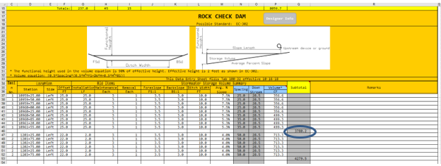
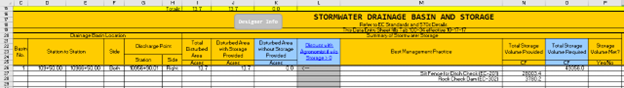
In Tabulation 100-34, choose the Rock Check Dam (570-2) option from the pull down menu in the Best Management Practice column. Enter the subtotal for Basin No. 1 from Tabulation 100-32 above into the Total Storage Volume Provided column in Tabulation 100-34, see below.
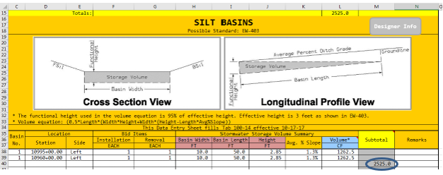
Filling in Tabulation 100-14, Silt Basins
If silt fence ditch checks do not provide the required storage volume, silt basins can be used to supplement silt fence ditch checks. The Silt Basins tab self-calculates storage volume based on the inputted width, length, and height.
For this project, two silt basins are included in Basin No.1. The figure below shows Tabulation 100-14 filled in for Basin No. 1.
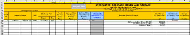
In Tabulation 100-34, choose the Silt Basin (EW-403) option from the pull down menu in the Best Management Practice column. Enter the subtotal from Tabulation 100-32 above into the Total Storage Volume Provided column in Tabulation 100-34, see below.
Filling in Tabulation 100-33, Temporary Sediment Control Basin
The last storm water storage device to consider for use is the Temporary Sediment Control Basin. These are required for drainage basins consisting of 10 acres or more of disturbed area. They can also be used to supplement silt fence ditch checks if they do not provide adequate storage volume.
For filling out the maintenance column, typically 3 cleanouts for each device is used. The maintenance number accounts for the number of times a clean out will be necessary.
Since Basin No. 1 consists of over 10 acres of disturbed area, at least one temporary sediment control basin is required. The figure below shows Tabulation 100-33 filled in for Basin No.1, 4, and 5.
Back to top