Content Information
On this page...
Concrete barrier rail consists of two types: permanent (BA-100s) and temporary (BA-401). Permanent concrete barrier rail is most commonly cast in place, while temporary concrete barrier rail is precast in short sections to allow it to be moved from location to location.
Back to topPermanent Concrete Barrier Rail
Permanent concrete barrier rail is a rigid barrier system consisting of reinforced concrete shaped to withstand a vehicular impact, see Figure 1. It is the only type of barrier that can be designed to withstand an impact from a semi-truck. It can be tied to an underlying pavement with reinforcing bars, attached to pavement with dowels, or mounted on a footing. Permanent concrete barrier rail should not be installed on slopes steeper than 10:1. Additionally, it generally should not be placed more than 15 feet from the edge of a roadway because of the danger of high angle impacts. Permanent concrete barrier should not be used when another type of barrier will suffice.
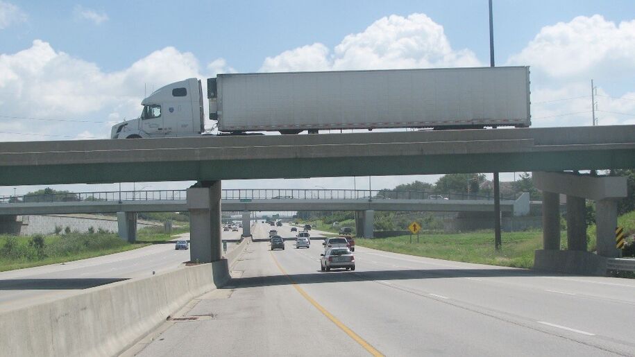
Figure 1: Permanent concrete barrier rail example.
The type of end section (BA-107 or BA-108) to use depends on expected posted speed. Due to the risk of vehicles tipping, BA-108 should be used only where posted speed is expected to be 30 mph or less, see Section 8A-4.
Considerations for permanent concrete barrier rail include:
- Zone of intrusion (ZOI), see Section 8A-6.
- Maximum longitudinal gap between two pieces of barrier rail, e.g. at a pavement joint, without using a cover plate is 4 inches.
- Vertical taper rate for transitioning the height of barrier rail, e.g. transitioning from 34 inches to 44 inches, is a minimum 10:1.
Sign posts and light poles mounted on top of concrete barrier must be breakaway.
Below are guidelines for choosing a barrier height:
Use a 44 inch barrier with reinforcing into the shoulder if the barrier is located more than 10 feet from a bridge pier not designed to take a 600 kip load, see Chapter 5 of the Roadside Design Guide and Bridges and Structures Bureau’s Design Manual 3.7.4.
Use a 54 inch barrier with reinforcing into the shoulder if the barrier is located 10 feet or less from a bridge pier not designed to take a 600 kip load, see Chapter 5 of the Roadside Design Guide and Bridges and Structures Bureau’s Design Manual 3.7.4. In the direction of traffic, the 54 inch barrier must extend a minimum of 60 feet leading up to the pier and 50 feet leading away from the pier. Use a minimum 10 foot length for transition height change from 44 to 54 inch tall barrier (or 1 foot length per inch height change).
Use a 54 inch barrier with dowels in the median on the approaches to and alongside all bridge piers and overhead sign truss supports in the median. 54 inch barrier must extend a minimum of 60 feet on each approach to the obstacle. See BA-150.
Use 454 inch barrier with reinforcing into shoulder when protecting a sign truss that is within 10 feet of the edge of traveled way. The 54 inch barrier must extend a minimum of 60 feet leading up to the sign truss support and 50 feet leading away from the truss support.
Use 44 inch barrier with dowels beyond the first 60' of barrier in the median.
Use 34 inch barrier with dowels beyond the first 60' of barrier on the shoulder.
Use 34 inch or 44 inch barrier with reinforcing into shoulder within the first 60' of a run of barrier (likely adjacent to a crash cushion).
Use 34 inch barrier with reinforcing into shoulder when protecting a steep drop off or retaining wall on the shoulder.
Use 34 inch barrier with dowels for all remaining cases.
Required clearances for specific features:
Overhead bridge pier columns and caps – These are considered critical structures to be protected. The preferred minimum horizontal clearance from the top traffic face corner of barrier to the obstruction is 3.25 feet at a height of 15’-5 above gutterline elevation. Since the height of a truck cargo box at maximum intrusion during a crash varies with the Test Level and the truck type, vertical clearance at the 3.25 foot horizontal limit may be adjusted in accordance with roadway conditions and associated ZOI envelopes shown in Section 8A-6. However, any proposal to reduce the horizontal clearance from 3.25 feet must be reviewed and approved by the Methods Engineer, and consultation with the Bridges and Structures Bureau is required. In a median installation, the loss of shoulder width to accommodate extra clearance is undesirable. Reducing the clearance to the minimum and maintaining the shoulder would be preferred.
Overhead and cantilever sign trusses – These are considered critical structures to be protected. The preferred minimum horizontal clearance from the top traffic face corner of barrier to the support columns is 3.25 feet. Any proposal to reduce the horizontal clearance from 3.25 feet must be reviewed and approved by the Methods Engineer, and consultation with the Bridges and Structures Bureau is required. Cases where sign support columns are proposed to be added to an existing single point median barrier with narrow shoulders are of special concern and must include discussion with both Design Bureau and Bridges and Structures Bureau personnel. In a median installation, the loss of shoulder width to accommodate extra clearance is undesirable. Reducing the clearance to the minimum and maintaining the shoulder would be preferred.
- Retaining walls - The preferred horizontal clearance is the dimension required to maintain the full clear ZOI for the barrier used and for the roadway conditions as indicated in Section 8A-6. Any proposal to reduce the horizontal clearance from the ZOI shown in Section 8A-6 must be reviewed and approved by the Methods Engineer, and consultation with the Bridges and Structures Bureau is required.
Light poles and sign posts - For light poles and sign posts mounted to roadway barriers (not including on bridges), these features must be breakaway and no specific clearance dimensions are required. For light poles and sign posts mounted to bridge barriers, see BDM Section 3.14.
Temporary Concrete Barrier Rail
Temporary concrete barrier (often referred to as TBR) is a semi-rigid barrier system consisting of precast reinforced concrete sections shaped to withstand a vehicular impact, see Figure 2.
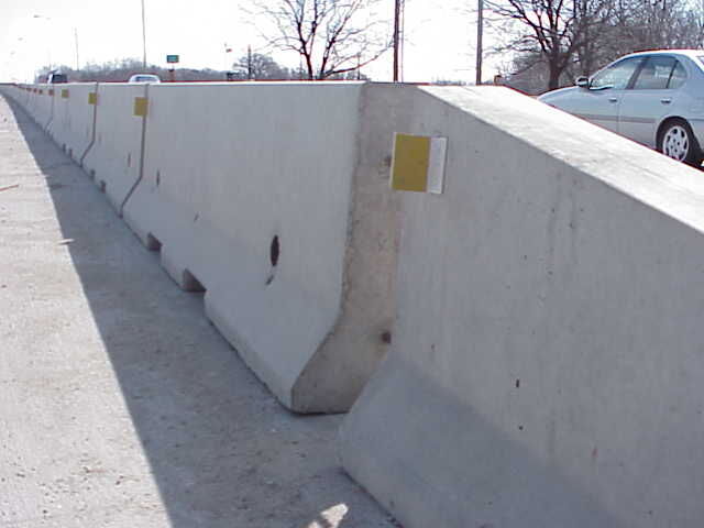
Figure 2: Temporary concrete barrier rail example.
The most common use for TBR is in work zones. Refer to Section 9B-9 for more information regarding TBR.
Back to top