Content Information
5B-1 Topsoil Replacement
The following guidelines for topsoil replacement serve as a supplement to Sections 314.12 and 314.12A of the Code of Iowa as well as Iowa DNR NPDES General Permit No. 2.
Topsoil Replacement Policy
To help the Department establish vegetation and reduce erosion, a minimum of 4 inches of topsoil should be placed in all areas not to be covered by concrete, asphalt or gravel. Exempt areas are discussed later in the section. To help fulfill this goal, the Design Bureau has established the following guidelines:
- Preferable: If sufficient topsoil can be generated from the project, cover all disturbed areas of the final template, other than pavement and shoulders, with 8 inches of topsoil.
- Acceptable: When topsoil quantity is limited, place 8 inches on the specified critical areas described below and 4 inches on all remaining disturbed areas.
- Minimum: 4 inches of topsoil is required on all disturbed areas.
Topsoil is a valuable resource, so stripping, salvaging, and spreading topsoil should be considered whenever possible. This will reduce the quantity of topsoil contractors will need to furnish.
Topsoil can be purchased if sufficient quantities cannot be generated from the project (discuss with Soils Design Section, Roadside Development, and the District). This will be more common with urban projects.
Specified Critical Locations
Topsoil placement thicker than the 4 inch minimum required is desirable at the following locations
- All sand/gravel cuts and fills including foreslopes, backslopes, ditch bottoms, etc. This will also address “slope dressing” concerns with sand.
- Exposed shale in backslopes and ditch bottoms.
- Exposed rock of any kind (including shale) in medians and in foreslopes.
- Backslopes, foreslopes, ditch bottoms, and internal borrows in very dense, hard clays or similar materials where establishment of vegetation is difficult. The Roadside Development Section may be consulted to assist in identifying these areas.
- Construction through unique areas such as abandoned coal mines, acidic soil locations, etc.
- Other specified critical locations identified by the Soils Design Section and/or others.
Topsoil should be placed within the final template as shown on the cross sections.
Exempt Areas
Topsoil should not be placed at the following locations:
- Outside ditch bottoms in rock-cut areas (except shale).
- Backslopes in rock-cut areas (except shale), whether the backslope cut is a steep “rock-type” backslope or a normal (i.e. 3:1) backslope.
Specific Responsibilities
These guidelines describe the responsibilities that the different sections have regarding topsoil replacement.
Soils Design Section
The Soils Design Section is responsible for:
- Providing CADD existing topsoil meshes from proposed/existing ROW to ROW lines, including temporary easements.
- Identifying the specified critical locations.
- Providing shrinkage estimates for topsoil.
Design Sections
The Design Sections are responsible for:
- Placing the proposed topsoil on the cross sections via template or mesh.
- Computing quantities and preparing the T sheets.
- Balancing topsoil cut and placement when possible.
- Verifying that enough topsoil is generated to provide replacement in all areas or adjusting the thickness placed as needed.
- Identifying general areas available for stockpiling topsoil, when requested.
- Estimating the amount of topsoil needed for earth shoulder construction.
Considerations Regarding Topsoil Replacement
Designers will encounter one of several situations illustrated in Table 5B.1:
- Not enough topsoil is available to meet the minimum guidelines for the project.
For this situation, strip and salvage available topsoil. Remaining topsoil will need to be purchased. Place topsoil according to the minimums as stated in the Topsoil Replacement Policy guidelines above.
- Enough topsoil is available to meet minimum guidelines, but not enough to meet acceptable guidelines.
For this situation, strip and salvage available topsoil. Place topsoil according to the minimums as stated in the Topsoil Replacement Policy guidelines above. Excess of topsoil should be placed in foreslopes and earth shoulder construction.
- Enough topsoil is available to meet acceptable guidelines, but not enough to meet preferable guidelines.
For this situation, strip and salvage available topsoil. Place topsoil according to the Topsoil Replacement Policy acceptable guidelines above. Excess of topsoil should be used for earth shoulder construction, or to be placed as additional material for foreslopes.
- Enough topsoil is available to meet preferable guidelines.
Strip and salvage topsoil needed. Place according to the Topsoil Replacement Policy preferred guidelines above. Excess of topsoil should be used for earth shoulder construction, or to be placed as additional material for foreslopes.
5B-2 Rock Excavation
This section discusses the procedure to be considered normal design practice for all projects involving rock excavation. The Soils Design Section in the Design Bureau will determine precisely where rock excavation is to occur.
Where the depth of rock excavation in any given area is 5 feet of less, design practice is to provide a norma ditch section. Review Detail 4110 .
Where the depth of rock excavation is greater than 5 feet, designers should prepare the necessary typical sections to convey rock excavation requirements for the project. Design Details 4110 or 4111 should be used as the basis for developing the necessary typical sections.
The development of the required typical section should be done jointly between the Design Section and the Soils Design Section to ensure that the optimum section and requirements are specified for the project
When the Soils Design Section indicates pre-splitting is required, it should be noted in the remark’s column of Tab 107-25
Steepened backslopes should be avoided in areas of shale, broken and weathered limestone, or similar rock.
Rock excavation should be bid Class 12 or Class 13 Excavation. Refer to Section 2102 of the Standard Specification for definitions of Class 12, Class 13 materials, and excavation.
5B-3 Culvert Excavation and Backfill
This section discusses excavation and backfill for pipe culverts, box culverts, and livestock passes installed under pavement. Pipe culverts installed under pavement are placed according to DR-101. Contractors may elect to install rigid pipes using the fill installation method; however, trench installation is more common. Flexible pipe requires trench installation. Regardless of pipe type, quantities will be based on a bedding thickness of 4 inches below the pipe
Excavation
Reinforced Concrete Pipe
In fill areas, assume the contractor will use the fill installation shown on DR-101. If the pipe is located in an area that will require a partial cut, see Figure 5B.1, calculate the quantity of Class 20 as described in Article 2402.04, B, 3 of the Standard Specifications. Remember to account for the thickness of the pipe and the 4 inch bedding.
In cut areas, the trench installation shown on DR-101 is used. Trench installation may also be used in partial fill areas. Refer to DR-101 for a cross section of the trench.
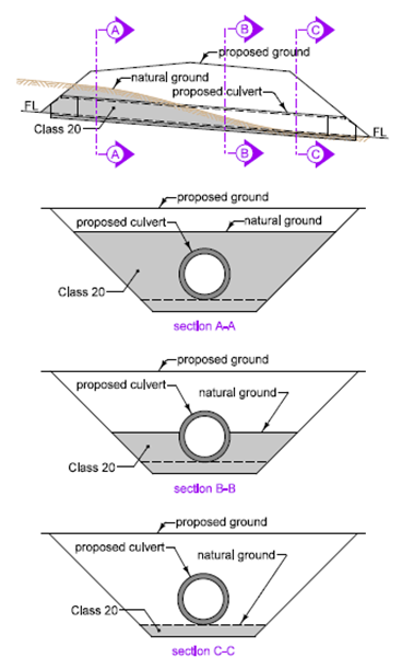
Figure 5B.1: Rigid pipe installation with partial cut.
Flexible or Unclassified Pipe
Flexible (metal or plastic) pipe is always installed using the trench installation shown on DR-101. Refer to DR-101 for a cross section of the trench. Calculate Class 20 up to existing ground or to 2 feet above top of pipe (or the minimum pipe cover shown on DR-104 if greater than 2 feet) for the length of trench, see Figure 5B.2. Remember to account for the thickness of the pipe and the 4 inch bedding.
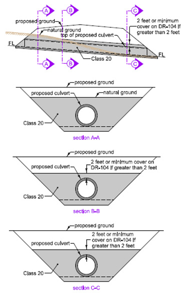
Figure 5B.2: Class 20 for flexible or unclassified pipe installations.
Unclassified pipe may be either flexible or rigid depending on the contractor’s choice. Designers should assume flexible pipe and calculate Class 20 the same as for flexible pipe. Since the pipe thickness isn’t known, use concrete pipe thickness to be conservative.
Reinforced Concrete Box Culvert and Livestock Pass
The Bridges and Structures Bureau calculates Class 20 for RCB or Livestock Pass as described in Article 2402.04, B, 4 of the Standard Specifications. Refer to DR-111 for a cross section of the trench.
Backfill
Pipe Culverts Installed Under Pavement
The quantity of flooded backfill is equal to floodable backfill plus porous backfill. Refer to Tabulation 104-3.
H in DR-101 is defined as the cover over the pipe. Because of the slopes of the pipe and pavement, this depth can vary along the pipe. For these calculations, focus on the depth under the pavement area. If any depth of cover under the pavement is less than or equal to 4 feet, include the flowable mortar quantity. Two quantities will need to be determined: flooded backfill and flowable mortar.
Quantities for Flooded Backfill are calculated using the proposed ground. Where the proposed ground is greater than 5 feet above the top of pipe, use top of pipe plus 5 feet as the maximum trench depth (see Note 8 of DR-101). This maximum is based on Article 2416.03, C of the Standard Specifications. Care should be taken to estimate Flooded Backfill as accurately as possible.
For letdown structures, use Class C bedding under the letdown portion and Class B bedding on the portion of the pipe under the roadway. Flooded backfill quantity should be calculated as if the pipe continued to the foreslope at the same slope as the cross road portion.
A gap will exist between the top of the flowable mortar and the normal top of subgrade, see Figure 5B.3. If this gap exceeds 6 inches (e.g. superelevated curves), fill the area with Special Backfill or Modified Subbase. If it is 6 inches or less, fill the area with Granular Subbase or Modified Subbase.
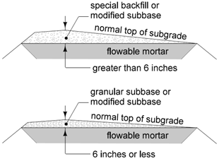
Figure 5B.3: Gap between flowable mortar and normal top of subgrade.
Pipe Culverts Installed outside of Pavement
For roadway pipe culverts not installed under pavements, bedding and backfill (if excavated material) is incidental to pipe culvert and pipe excavation, respectively.
Box Culverts and Livestock Passes Installed under Pavement
Normally, culverts are let a year in advance of the paving and are backfilled according to the Embankments Adjacent to Culverts and Structures specifications (see Section 2107 of the Standard Specifications), and the Placing Backfill Materials and Embankments Adjacent to Bridges, Culverts, or Structures specifications (see Section 2402 of the Standard Specifications). Occasionally, the pavement above the culvert will be constructed in the same year as the culvert. In these cases, a combination of flooded backfill and suitable backfill is used to prevent pavement issues caused by settlement of this material. Floodable backfill is placed to a height of 5 feet. The remaining backfill is suitable soil. Refer to DR-111 for a cross section. The quantity of flooded backfill is equal to floodable backfill plus porous backfill, see Tabulation 104-4.
Designers should keep in mind that although a project may be graded one year and paved the next, the timing of the grading and paving projects may result in less than a full calendar year between the grading and paving. In cases such as these, designers may still want to consider using flooded backfill.
Box Culverts and Livestock Passes Installed outside of Pavement
For roadway box culverts not installed under pavements, backfill is placed according to Article 2402.03, H of the Standard Specifications.