Content Information
On this page...
This section provides guidelines for determining clear zone distances on primary highways. The location from which the clear zone is measured (“edge of traveled way” or “back of curb”) and the appropriate procedures for determining the clear zone width depend on the type of highway.
Back to topDefinition
A clear zone is defined as a roadside area that is free of objects, where an out-of-control vehicle can traverse safely. The width of a clear zone is measured relative to the edge of traveled way. How far the clear zone extends from this point can be expressed in two ways: design clear zone distance, or provided clear zone distance.
Design Clear Zone Distance
This is the width of clear zone that should be provided along a given roadway for a specific project. This distance is chosen from one of the clear zone tables and is based on traffic speeds, traffic volumes, horizontal curvature, and roadside geometry. Design clear zone distance can change along a project. Such a change may result from a change in design speed, traffic volumes, horizontal curvature, or roadside geometry.
Provided Clear Zone Distance
This is a measure of the actual clear zone width that is available along a given roadway. This distance is measured from the edge of traveled way out to the face of the nearest object. The provided clear zone distance should be equal to or greater than the design clear zone distance.
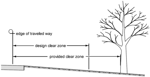
Figure 1: Example of possible clear zone distances at a given point along a roadway.
While the design clear zone distance may remain constant along a segment of roadway, provided clear zone distance distances may vary considerably. As seen in Figure 1, the provided clear zone distance extends from the edge of traveled way out to the nearest hazard – a large tree in this case. However, just upstream or downstream of this tree, the nearest hazard may be much farther from the roadway. Thus, the provided clear zone distance at these locations may be significantly larger. Figure 2 demonstrates this possibility. The provided clear zone distance is much larger just upstream and downstream of each object.
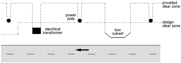
Figure 2: Example of how clear zone distances may vary along a roadway.
Back to topClear Zone Distances for Highways
For freeways, expressways, rural two lane highways, and transitional facilities, select the design clear zone distance from the appropriate clear zone table below. For low speed urban facilities, refer to the discussion near the end of this section.
Within the table, use bi-directional mainline traffic volumes (ADT) that would be expected in the design year of the project. For ramps that are separate from the mainline, use the ramp volume. Ramp tapers and auxiliary lanes are special cases and are discussed later in this section.
Since traffic speeds, traffic volumes, horizontal curvature, and roadside geometry can all vary throughout a corridor, clear zone distances must be determined for each distinct roadway segment.
Right-of-way availability, environmental concerns, or economic factors may impact the ability to provide clear zones. Where clear zone distances do not meet the requirements set forth in this chapter, document this according to Section 1C-8.
Slopes
A vehicle leaving the roadway will normally encounter some type of slope – either a foreslope or a backslope. A roadside cross section may contain multiple foreslopes, multiple backslopes, or combinations of both. The steepness of a roadside slope can affect a vehicle’s stability and trajectory. It is one of the factors used in the determination of clear zone widths. As used in this manual, slopes are defined as a ratio of horizontal distance to vertical rise or fall. For example, a 4:1 foreslope is a slope that falls away one foot for every four feet. Figure 3 illustrates this concept.
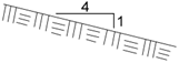
Figure 3: A 4:1 foreslope.
Foreslopes and backslopes that are too steep can be considered hazardous and, therefore, cannot be counted as part of a clear zone. The following sections describe how foreslopes and backslopes are classified based on their steepness.
Foreslopes
A foreslope is a parallel slope that falls away from the roadway. Foreslopes are typically encountered where the roadway is higher than the surrounding natural ground line. Where a roadside ditch exists, a foreslope connects the edge of the shoulder to the bottom of the ditch. Foreslopes are identified as recoverable, non-recoverable, and critical. Each of these features is discussed below.
Recoverable
A recoverable foreslope (4:1 or flatter) is a slope on which an errant motorist is likely to regain control. Recoverable foreslopes can be counted as part of a clear zone and their use is preferred whenever possible (see Figure 4).
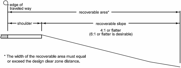
Figure 4: Example of a recoverable foreslope design.
Non-Recoverable
A non-recoverable foreslope is a slope on which an errant motorist will unlikely be unable to stop and will continue on to the bottom of the slope. Non-recoverable foreslopes are those steeper than 4:1 to as steep as 3:1. Complete recovery usually will not occur until the vehicle travels a certain distance beyond the base of such a slope. Therefore, a recoverable area free of objects should be provided at the toe of a non-recoverable slope.
Non-recoverable foreslopes cannot be counted as part of a clear zone (see Figure 5).
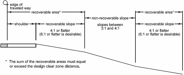
Figure 5: Example of a non-recoverable foreslope design.
Critical
A critical foreslope (steeper than 3:1) is a slope on which most vehicles would be expected to roll over. Critical foreslopes should be evaluated for treatment (refer to Section 8A-4).
Critical foreslopes cannot be counted as part of a clear zone (see Figure 6).
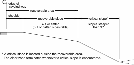
Figure 6: Example of a critical foreslope design.
Backslopes
A backslope is a parallel slope that falls toward the roadway, and is typically encountered where the roadway is lower than the natural ground line. Where a roadside ditch exists, a backslope also connects the bottom of the ditch to the surrounding ground. The effects of backslopes on vehicle dynamics have not been studied as extensively as those of foreslopes. Therefore, the relative safety effects of various backslope designs are not as well understood. Nevertheless, flatter backslopes are preferred whenever possible.
Moderate
A moderate backslope (2.5:1 or flatter) is a slope on which most vehicles should be able to traverse safely. Moderate backslopes are not considered hazardous.
Severe
A severe backslope (steeper than 2.5:1) is a slope on which some vehicles might be expected to roll over. Severe backslopes may be considered hazardous and should be evaluated for treatment (refer to Section 8A-4). Severe backslopes cannot be counted as part of a clear zone.
Back to topAdjustment at Horizontal Curves
The design clear zone distance should be adjusted at certain horizontal curves. Adjust the width of the clear zone at a curve when a crash history or engineering judgment suggests the need for additional width. Otherwise, adjust the width when all of the following criteria are met:
The design speed of the roadway is 55 mph or greater.
The radius of the curve is 2860 feet or less.
The curve occurs on a normally tangent alignment (one where the curve is preceded by a tangent more than one mile in length).
Use the following equation to determine the adjusted clear zone distance when widening at horizontal curves:
\(CZ_C\) = \(CT_T\) × \(KC_Z\)
where:
\(CZ_C\) = adjusted design clear zone distance at curve (rounded to nearest foot)
\(CT_T\) = design clear zone distance on tangent segment
\(KC_Z\) = curve adjustment factor
Table 1: KCZ (Curve Adjustment Factors)
As Figure 7 shows, the clear zone should be adjusted only on the outside of the first curve following the tangent. If the alignment is generally curvilinear, no adjustment factor should be applied. Similarly, if the alignment is curvilinear preceding the curve in question, then no adjustment factor should be applied.
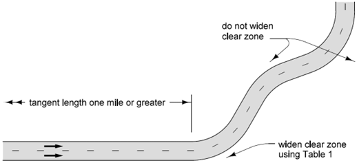
Figure 7: Clear zone adjustment at horizontal curves.
Figure 8 shows the appropriate method for initiating and terminating an adjusted clear zone width at horizontal curves.
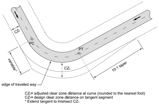
Figure 8: Initiating and terminating adjusted clear zone width at curves.
Back to topRamp Tapers and Auxiliary Lanes
Determining clear zone distances for ramp tapers, auxiliary lanes, climbing lanes, or turning lanes involves a three step process:
Determine the clear zone distance from the edge of the through lane based on through lane traffic volume and speed.
Determine the clear zone distance from the edge of the auxiliary lane based on auxiliary lane traffic volume and speed.
Compare the calculated distances. The distance which extends to a point further from the edge of the auxiliary lane is used as the overall clear zone distance for this location. Refer to Figure 9 for an example.
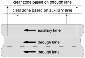
Figure 9: Example of a clear zone calculation for auxiliary lanes.
For the example shown in Figure 9, the clear zone distance for the through lanes would be the controlling clear zone for this road segment.
Back to topClear Zone Distances for Transitional and Low Speed Urban Facilities
Transitional and urban roadway environments present unique sets of circumstances, often with conflicting interests sharing limited right-of-way. For transitional facilities, speed limits are typically between 35 and 45 mph, gutter sections are being introduced, and right-of-way is being reduced. With low speed urban facilities, on-street parking is common, and bicyclists and pedestrians may be present. For both types of facilities, trees, light poles, traffic signals, and other roadside objects tend to be located near the traveled portion of the roadway.
Lateral Offset
Lateral offset to all obstructions – including crashworthy devices – must be provided. Lateral offset provides clearance for mirrors on large trucks and for opening curbside doors of parked vehicles.
Where curb is present, the minimum lateral offset is 1.5 feet behind the face of curb. Whenever possible, provide a minimum of 3 feet at intersections and driveways to accommodate turning trucks and to improve sight distance. On facilities without a curb, the minimum lateral offset is equal to the normal shoulder width. Where shoulder widths are less than 4 feet, provide a minimum lateral offset of 4 feet.
Clear Zone
Transitional Facilities
For transitional facilities, designers should use either the Preferred Clear Zone Distances (feet) or Acceptable Clear Zone Table. If curb and gutter exist, or the speed limit is anticipated to be lowered in the near future, the clear zone for low speed urban facilities discussed below may be used.
Low Speed Urban Facilities
Preferably, all roadside objects should be placed beyond the chosen clear zone distance. If this placement is not practical, devices proven to be breakaway, such as fire hydrants and certain sign supports, may be constructed or allowed to remain in place within the clear zone – with appropriate lateral offset. Keep in mind that breakaway objects could become airborne during a crash ; therefore, breakaway devices may not be recommended for locations between the curb and sidewalk if high volumes of pedestrian traffic are expected.
For curbed urban roadways, measuring clear zone distance from the back of curb is preferred; however, measuring from the edge of traveled way is acceptable. For non-curbed sections, the clear zone distance is measured from the edge of traveled way.
For roadways with a posted speed of 35 mph or less, the preferred clear zone distance is 10 feet and the acceptable clear zone distance is 8 feet. Where the speed limit is 25 mph or less, the preferred clear zone distance remains the same, but the acceptable clear zone distance may be reduced to 6 feet. If sidewalks are not present, consider using a clear zone value that will accommodate them in the future.
If a turning lane, auxiliary lane, or paved shoulder results in a curb that lies outside the normal roadway width, provide a minimum 4 foot clear zone measured from the back of this curb. Provide appropriate lateral offset behind the face of curb.
Whenever practical, the maximum amount of clear zone should be provided, especially on projects where safety is the principal goal. Where minimums cannot be met, design variances may be justified on a case-by-case basis.
Portions of side streets under a city’s jurisdiction may be reconstructed as part of a project on a primary highway. For these streets, follow the guidance in the Local Systems Bureau’s I.M. 3.240. The Department retains the right to ensure that adequate sight distance is provided at intersections or accesses.
Back to topClear Zone Distances for Temporary Traffic Control Zones
Clear zone distances for temporary traffic control zones must be approached from a unique perspective. Unlike permanent situations where the life of a project can be anywhere from 20 to 50 years, the life of a temporary traffic control zone is measured in weeks or months. Providing full width clear zones in temporary situations proves not to be cost beneficial. Therefore, field performance and engineering judgment have been used to determine reasonable clear zone distances for temporary traffic control zones.
On staged or multi-year projects, traffic may at times be returned to normal operations – such as between stages or over winter. During these times, provide full width clear zones according to the clear zone tables.
Use the following clear zone distances for temporary traffic control zones:
On low speed urban roadways: 6 feet or 1.5 feet behind the face of the adjacent curb, whichever is less.
On two lane rural roadways with alternating one way traffic: 10 feet or the outside edge of the adjacent shoulder, whichever is less.
On two lane rural roadways where both lanes of traffic remain open: 10 feet or the outside edge of the adjacent shoulder, whichever is less. Whenever reasonably possible, fixed objects should not be allowed with 10 feet of the roadway. A fixed object is defined as an object, device, or appliance that is fastened or secured at a specific location, for example a tree or temporary concrete barrier.
On freeways and expressways: 15 feet or the outside edge of the adjacent shoulder, whichever is greater.
For situations not covered, a site specific determination of appropriate clear zone distance must be made. Items to consider include traffic volumes, expected speeds, length of the temporary traffic control zone, and duration of the project.
Temporary barrier rail may be required in some areas listed above. See Section 9B-9 for temporary barrier rail requirements.
Back to topVertical Clear Zones
The horizontal clear zones described previously should also extend vertically a sufficient distance to effectively eliminate objects. Where feasible, the clear zone should extend vertically at least 14 feet 6 inches (see Figure 10). If this is not possible, treatment may be warranted.
Keep in mind the difference between vertical clearance and vertical clear zone. The values for vertical clearance that are provided in Section 1C-1 must be maintained above all traffic lanes and shoulders. The vertical clear zone referred to above should be maintained throughout the entire horizontal clear zone.
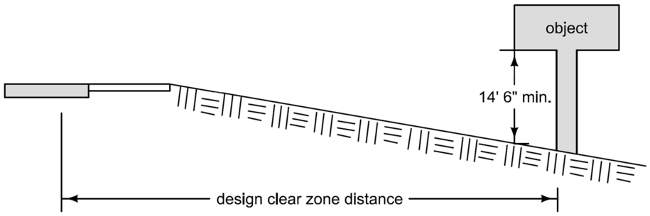
Figure 10: Vertical clear zone example.
Back to top
Preferred Clear Zone Distances (feet)
(Based on AASHTO Roadside Design Guide, 4th Edition)
* Backslopes as steep as 2.5:1 can be considered as part of the clear zone, as long as they are relatively smooth and do not contain any fixed objects. Refer to Section 8A-4 of the Design Manual for information regarding backslopes steeper than 2.5:1.
** Since a vehicle traveling on a slope steeper than 4:1 is likely to be diverted to the bottom of the slope, the width of any slope steeper than 4:1 cannot be counted in the clear zone determination. Refer to Section 8A-2 of the Design Manual for information on providing clear recovery areas at the base of steep slopes.
Back to top
Acceptable Clear Zone Distances (feet)
(Based on AASHTO Roadside Design Guide, 4th edition)
* Backslopes as steep as 2.5:1 can be considered as part of the clear zone, as long as they are relatively smooth and do not contain any fixed objects. Refer to Section 8A-4 of the Design Manual for information regarding backslopes steeper than 2.5:1.
** Since a vehicle traveling on a slope steeper than 4:1 is likely to be diverted to the bottom of the slope, the width of any slope steeper than 4:1 cannot be counted in the clear zone determination. Refer to Section 8A-2 of the Design Manual for information on providing clear recovery areas at the base of steep slopes.
Back to top