
Content Information
On this page...
The most important element in the transition area is the taper that provides channelization. An inadequate taper produces undesirable traffic operations, which could lead to crashes within the work area. This section describes the different types of tapers and their uses.
The following equations are used when determining taper lengths:
where:
L = base taper length in feet.
W = width of offset in feet.
S = posted speed in mph.
The taper length formulas above apply to ideal conditions (flat grades, straight alignment, etc.) and should be adjusted to provide adequate sight distances on approaches to channelization. Other field restrictions, such as proximity of ramps or crossroads to the work site, may warrant adjustment of the taper lengths. Better traffic operation will result when the taper lengths are increased rather than decreased below the minimum desirable lengths.
Back to topMerging Taper
A merging taper, see Figure 1, is used on multilane roadways when the number of traffic lanes is reduced. L is determined using the equations above with W being the width of the lane closed. The length of the merging taper must be long enough for vehicles traveling side-by-side to adjust their speeds and merge into a single lane before the end of the transition.

Figure 1: Merging taper.
Back to topShifting Taper
A shifting taper, see Figure 2, is used to direct traffic into a different travel path when a merge is not required. L is computed from the formulas above. When using the formulas to calculate the length of a shifting taper, the value of W should be the lateral shift in feet, which may be more or less than a lane width.
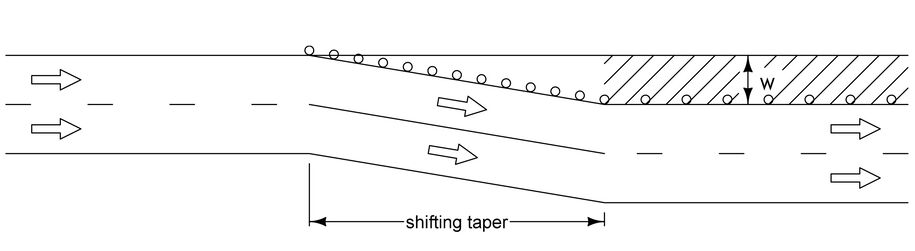
Figure 2: Shifting taper.
On high-speed facilities or facilities that carry high traffic volumes, the full values of L should be used where space is available in order to provide a high level of service. Similarly, any time existing pavement is available to do so, the full values of L should be used. If space or existing pavement isn’t available to use full values of L, then 3L/4 should be use used. Shifting tapers should not be less than L/2 or 200 feet, whichever is greater. Shifting tapers shorter than 200 feet, regardless of the lateral shift, may lead to unsatisfactory operation.
An alternate method for shifting traffic is the use of horizontal curves designed for normal highway speeds, see Section 2D-1. Horizontal curves allow the completion of lateral shifting maneuvers in less longitudinal distance than shifting tapers. Horizontal curves work best when the lateral distance is large, as in the case of high speed median crossovers (see Section 3E-3). However, care must be exercised so that differences in highway geometry do not present a safety problem.
Back to topShoulder Taper
When a shoulder is closed on a high-speed facility, it should be treated as a closure of a portion of the roadway, and the work area on the shoulder should be preceded by a shoulder taper, see Figure 3. Shoulder tapers should have a minimum length of L/3 where L is computed using the formulas on page 1 with W being the width of the shoulder. Refer to Standard Road Plans TC-202 and TC-402.
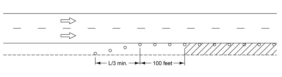
Figure 3: Shoulder taper.
Back to topTwo-way Traffic Taper
Two-way traffic tapers, see Figure 4, are used in advance of a work area that occupies a portion of a two-way roadway in such a way that traffic from each direction must alternate through the work area. Traffic is controlled by a flagger or a temporary signal device. In this situation, a short taper having a maximum length of 100 feet should be used to direct traffic into the one-lane section. A longer taper encourages high-speed and early lane changes, possibly directing motorists into opposing traffic.
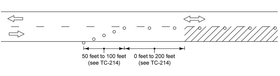
Figure 4: Two-way traffic taper.
Back to topDistance between Tapers
Sometimes several tapers must be used together in a series to provide adequate traffic control. When multiple tapers are used, sufficient distance must be maintained between them to give the motorist time to prepare for the next maneuver. Additional signing may be necessary and the motorist needs time to process the information. Figure 5 shows examples of multiple taper use. Tapers should be carefully located and spaced to accommodate traffic at ramps and intersections, particularly in urban areas.
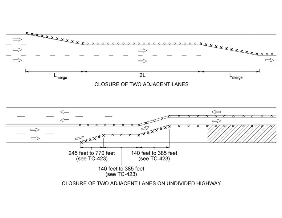
Figure 5: Use of multiple tapers.
Back to topSpacing of Channelizing Devices in Tapers
Refer to Section 9B-3.
Back to top