
Content Information
On this page...
Temporary median crossovers are used for a variety of reasons including diverting traffic around work areas and diverting traffic in areas where two lane highways are being converted to four lane divided highways. Three types of temporary median crossovers exist: one directional (Figure 1), two directional (Figure 2), and median crossings at interchanges (Figure 3). The PV-500 Series Standard Road Plans provide construction details for one directional and two directional high speed temporary median crossovers with standard median widths. Road Design Detail 531-2 provides construction details for temporary median crossovers at interchanges.

Figure 1: One directional median crossover.

Figure 2: Two directional median crossover.
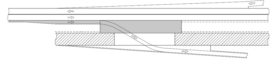
Figure 3: Median crossover at interchange.
Several engineers from the Districts and the Design and Project Management Bureaus discussed the option of letting temporary median crossovers earlier in the fiscal year (i.e., the July or August letting). This could be either an independent project or part of a larger construction project. The recommendation of the group was median crossovers and other necessary work required for the construction staging be constructed early in the fiscal year (thru either a separate project or part of the major project). If an independent crossover project is desired, it should be established at the inception of the project. In general, crossovers should be removed after the completion of the project; however, if crossovers are placed in optimal locations for future projects, they have the potential to generate substantial cost savings and should be left in place. Both topics should be addressed early in project development at the concept and field exam stages.
Link to the final median crossover report (562.78 KB) .pdf
Back to topDesign Considerations
Several considerations are involved with the design of a temporary median crossover:
The desirable design speed for median crossovers should be the posted speed prior to the construction area. In constrained areas, the minimum design speed may be reduced to 10 mph below the posted speed limit or lower if necessary. The PV-500s are for high speed crossovers. Lower speed crossovers in constrained areas will require a special design.
Temporary median crossovers should be located to provide the maximum advance warning to the driver based on the vertical and horizontal alignment at the site. The driver should be able to see the entire crossover area well in advance of the median crossover.
Desirably, temporary median crossovers should not be located within horizontal curves or in locations where the elevations of the inside edges of pavement are not equal.
Advance signing and proper pavement markings are also necessities for the safe operation of a temporary median crossover. Standard Road Plans TC-61 and TC-62, provide traffic control and pavement marking details for temporary median crossovers.
Access points should be avoided within or near a temporary median crossover.
Standard Road Plan DR-502 applies to two directional crossovers. Road Design Detail DR-504 applies to one directional crossovers. In certain situations, a cross roadway culvert may be used in place of Road Design Detail DR-504.
Back to topExample using COGO
A single lane, one directional, temporary median crossover is required to redirect traffic around a work area. The road is a rural expressway with a 50 foot median and has a posted speed of 65 mph. The width of a crossover (W) should equal the approach lane width plus 2 feet on each side, see Figure 3. For a single lane crossover, the width should be W = 12’ + 2’ + 2’ = 16’. To simplify construction, the radii for the crossover and all offsets and drops are measured to the edge of the 16 foot lane. The 12 foot lane lines are for pavement markings only.
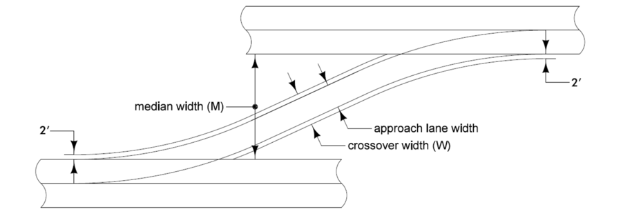
Figure 4: Establishing crossover pavement width.
For temporary median crossovers, the radius is set at 3500 feet and the superelevation rate is set at 2%.
Curves R1 and R2 are normally the same to permit use of the crossover in either direction of travel.
A transition length, L, is provided between the reverse curves to permit change in cross slope. The length L is twice the “x” value found in the superelevation tables in Section 2A-3. This length will accommodate reversal of the 2% normal crown slope at the selected design speed, which will be 65mph (the posted speed before the construction area). Although the width of the pavement is actually 16 feet, it is striped as a 12 foot lane. Therefore, Table 2 in Section 2A-3 is used to determine “x” for a single lane crossover. For a design speed of 65 mph, x = 56 feet, thus L = 2 x 56’ = 112 feet.
The median width for calculation purposes is 46 feet (50’-2’-2’ = 46’) because the 3500 foot radius curves are located at the edge of the 16 foot lane, which ties into a 2 foot parallel offset from the inside edge of slab, see Figure 3.
Using Table 2 in Section 2A-3, the distance to 2% (x) for 65 mph is 56 feet. The incomplete algorithm with Geopak cogo can be used for the calculation of the median crossover geometry. The commands below, included as a portion of an input file, produce the illustration in Figure 4.
LOCATE 10000 CHA ML080 STA 250+00 OFF -23
LOCATE 10001 CHA ML080 STA 260+00 OFF -23
LOCATE 10002 CHA ML080 STA 250+00 OFF 23
LOCATE 10003 CHA ML080 STA 260+00 OFF 23
ALI DET3 INC
POT 10000 TD 10000 TO 10001
CUR 10010 TL 0 RAD 3500 P DEF ?
POT 10011 TL 56
POT 10012 M DEF 90 TL 16
POT 10013 P DEF 90 TL 56
CUR 10014 TL 0 RAD 3500 M DEF ?
POT 10003 TL ? TD 10002 TO 10003
END ALI
STO CHA DET3 CUR 10010 10011 10012 10013 CUR 10014 STA 3+00
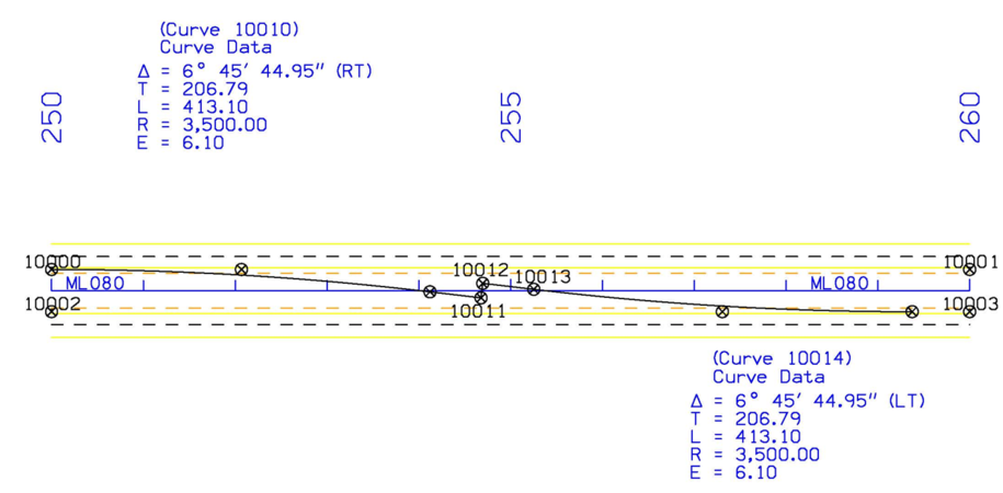
Figure 5: Temporary median crossover geometry for example problem using COGO.
Back to top