Content Information
On this page...
The purpose of an S1 Event or work effort is to: 1) review the proposed alignment and grade of a project for potential major soil related (geotechnical) problems affecting design and constructability; and 2) to identify multiple locations as potential borrow sources.
An S1 is typically accomplished by an office review of all available project and reference materials and by a field review, but without exploratory drilling or detailed geotechnical analysis.
Back to topReference Documents
Project inputs (documents) that may be provided for initiation of an S1 work effort include, but are not limited to:
Available Environmental Assessment (EA) and Environmental Impact Statement (EIS) reports.
- Proposed corridor limits.
- Documentation on the type of project.
- Aerial photo layout.
- Proposed grades and alignments.
- A general estimate of borrow needs.
- Anticipated project limits (termini).
Reference materials researched as part of the S1 effort also commonly include, but are not limited to:
- Available topographic maps.
- Soil surveys.
- Historical aerial photographs.
- LiDAR imagery.
- Previous project design.
- As-built plan information.
S1 Event Scope
A written S1 submittal (i.e., memo) reports the findings of: 1) the alignment and grade review, noting major or project stopper geotechnical related problems, issues and other observations/concerns; and 2) documentation of the multiple potential borrow sites. See example S1 submittal Memo with aerial photographs.
Grade and Alignment Review
A review of the grade and alignment is made to evaluate potential geotechnical issues (i.e., project stoppers) within the proposed corridor that could prevent the project from being completed, require an alignment change, and/or influence borrow selection. The identified geotechnical issues will be explained in detail on how they would affect the proposed project. These geotechnical issues could include, but are not limited to:
- Swampy areas (i.e., potential wetlands).
- Sinkholes.
- Abandoned mines.
- Peat/organic materials.
- Shallow bedrock.
- Faults.
- Alluvial channel fills (floodplains).
- Extreme cuts and/or fills.
Annotated aerial photos identifying the areas where potential geotechnical issue(s) occur should be included with the S1 submittal. As a minimum, include:
One photo showing an overall view of the potential geotechnical issues, if possible.
Separate enlargements of the individual geotechnical issue areas.
Potential Borrow Sites
The project borrow need and/or distribution is not always available at the time of the S1 work effort; therefore, to cover all possibilities related to how much borrow material might be needed and where, the number of potential borrow sites considered is almost always in excess of what will possibly be needed and ultimately used. Documentation regarding the borrow sites should include, and explain the reasons for, the number of borrow sites. Documentation should also include sufficient detail for each borrow selection, such as: 1) size of area identified (i.e., parcel or potential area of acquisition); 2) the type of soil material that is potentially available (Select, Class 10, etc.); 3) the probable type of borrow (pond, drainable, backslope, etc.); and 4) parent material (loess, glacial till, alluvium, etc.).
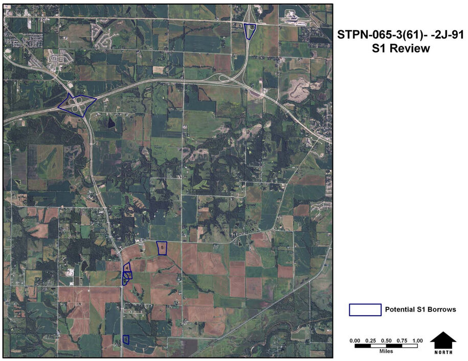
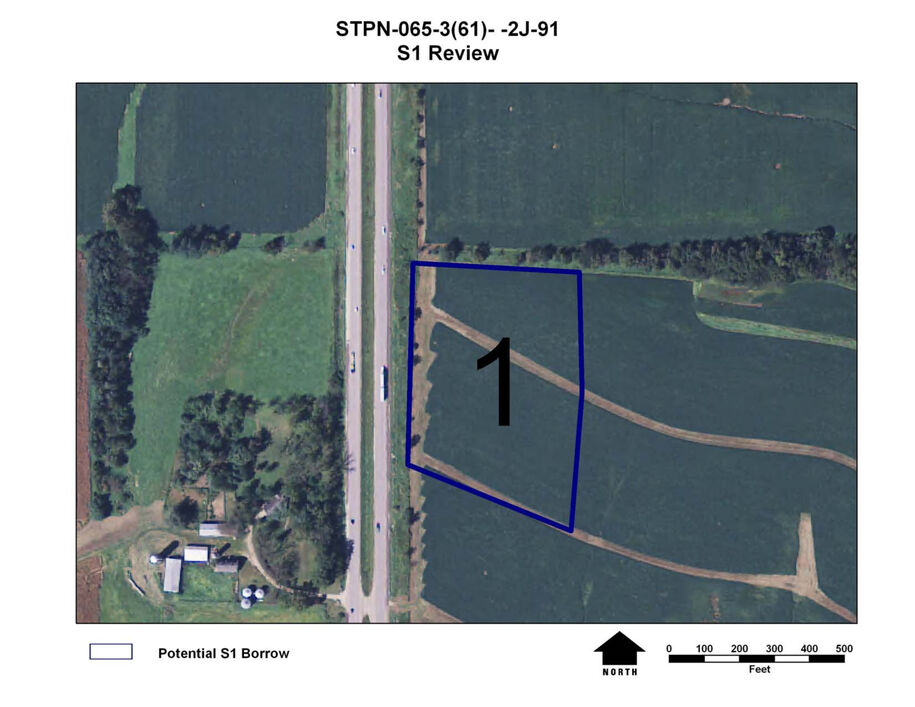
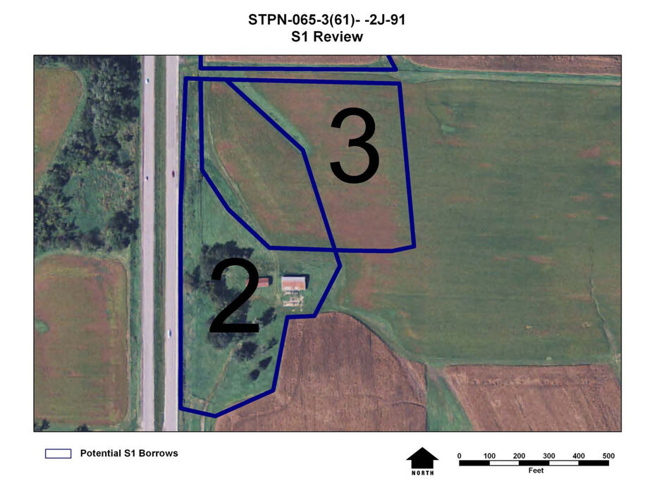
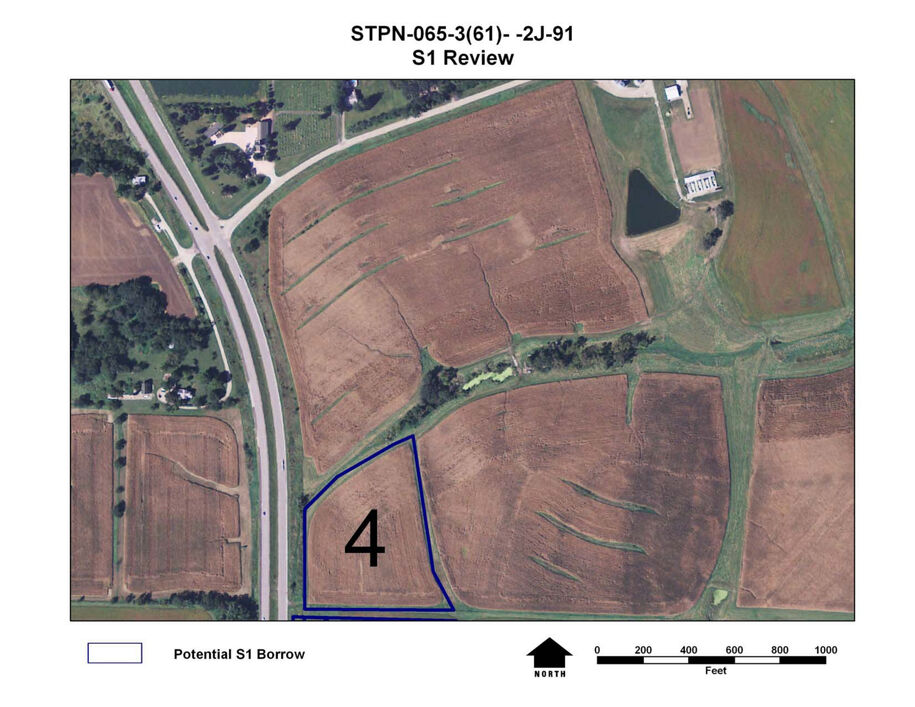
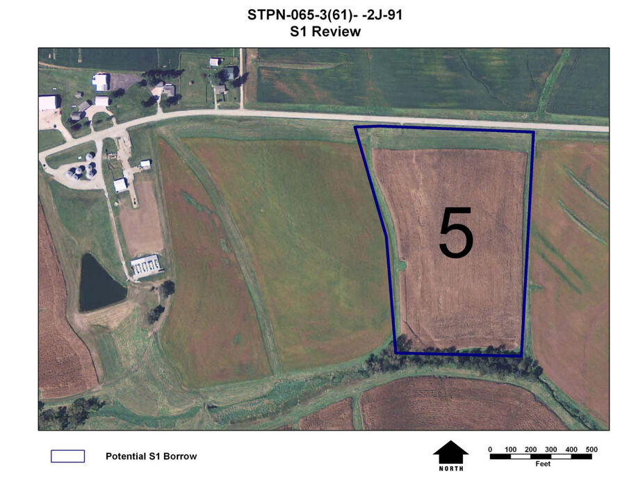
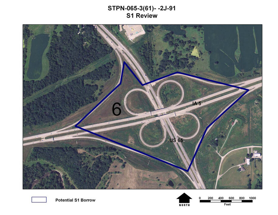
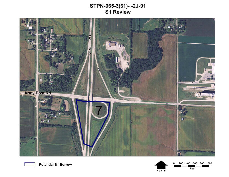
Annotated aerial photos (Figure 1) of the potential borrow sites should be included with the S1 submittal. As a minimum, include:
One photo showing an overall view of the sites, if possible.
Separate enlargements of the individual prospective sites.
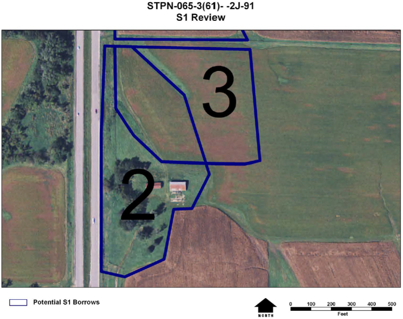
Figure 1: Annotated aerial photograph.
Each photo should be annotated with a north arrow, scale, a general outline of the proposed site or sites, and an identification number assigned to each potential site to facilitate subsequent discussions. Additional information may be appropriate such as road names, dimensions, or distances from easily identifiable land or building features to help S1 submittal recipients locate the potential sites.
Initial Identification: Initial borrow identification is accomplished by reviewing, at a minimum, the following:
GIS information:
- Topographic maps.
- Aerial photographs.
- Soil survey maps.
- Wetland maps.
- Geologic borings.
- Mining maps.
- LiDAR.
- As-built plans and DOT borings.
A field review is then conducted to further evaluate and select the multiple initial potential borrow sites. An important and mandatory part of this field review is to look for new development (such as new houses) that would eliminate a potential borrow site from consideration.
Selection of Sites: The borrow selection is based on some or all of the following considerations:
- Minimizing the number of borrows and land use impact.
- Total borrow need.
- Hauling distance.
- Hauling barriers (rivers, etc.).
- A borrow site’s potential to produce select for subgrade treatment (this is not always accomplished).
- Potential landlocked parcels, irregular shaped parcels.
- Proximity to farmsteads, homesteads, lakes, parks, and other sensitive features.
- Avoidance of environmental/cultural sites and issues (wetlands, historical sites, etc.).
- Restrictions such as the Loess Hills region, Century farms, pipelines, etc.
S1 Event Submittals
Back to topDraft S1 Submittal
The draft submittal consists of an email and memo following the S1 Event boiler plate. Use the following boiler plates for submittals: 1) email; and 2) memo. The draft submittal should include all photographs for identifying the geotechnical issues and borrow sites. Each photo should be annotated with a north arrow, scale, a general outline of the proposed site or sites, and an identification number assigned to each potential site to facilitate subsequent discussions. Additional information may be appropriate such as dimensions or distances from easily identifiable land or building features to help with locating the potential sites.
The Draft S1 submittal should first be submitted to the Soils Design Section Engineer for peer review and comment. Comments should be documented, discussed, and addressed in the final submittal. The overall Soils Design Section review team should ultimately include:
- Soils Design Section Engineer.
- Soils Design Section Assistant Engineer.
Soils Design Section Geologists.
Final S1 Submittal
The Final S1 Submittal Memo (pdf) is placed in the S1 Submittal folder of the Soils folder of the Project Directory and an email is sent to the recipient list below with links or electronic files of the Final S1 Submittal. For consultants, the Final S1 Submittal is forwarded via email or ftp. The Final S1 submittal should be directed to:
- Project’s Design Section Engineer.
- Office of Design Engineer, Assistant Engineer – Development, Assistant Engineer – Support.
- District Engineer, Assistant District Engineer; District Construction Engineer.
- Photogrammetry Engineer and Survey Supervisor.
- Office of Right of Way – Office Director, Right of Way Design Supervisor, Acquisition Team Leader.
- Office of Location and Environment – Office Director, Wetland Section Supervisor, Cultural/Historic Resource Team Leader.
- Design Section Assistant Engineer and Design Section Technician.
- Roadside Development Section Supervisor.
- Soils Design Section Assistant Engineer and Geologists.
- Office of Construction and Materials – Earthwork Field Engineer.
Electronic Files
For internal Iowa DOT use, electronic files are copied to the project directory and links to the files are included in the email. The steps necessary for the development of the electronic files are included in the S1 file guideline.
Consultant generated electronic files will be submitted with final submittal via email or ftp. Electronic files should be developed according to Section 20B-71.
Electronic files for the S1 submittal should include and be named:
- S1 Submittal Memo: County# - 2 digits, Route# 3 digits, and Paren # - 3 digits_S1.pdf
- Google Earth: County# - 2 digits, Route# 3 digits, and Paren # - 3 digits_S1.kml
- Microstation: County# - 2 digits, Route# 3 digits, and Paren # - 3 digits _S1.sol
- Aerial Photos: County# - 2 digits, Route# 3 digits, and Paren # - 3 digits _S1borrowXX.jpg
Back to top
Final Submittal Memo


S1 file guideline
- Create a GIS folder under the Soils folder in the project directory.
Example:
W:\Projects\9106501009\Soils\GIS - Copy to the GIS folder the appropriate template files for GeoMedia (English or metric, north or south).
Example templates:
Template_Engsouth.gwt, UTM.csf, IowaEnglishS.csf, featuresEngSouth.mdb, extra_borders.mdb, etc. - Rename the geoworkspace template (.gwt) to identify the project (County # = 2 digits, Route # = 3 digits, Parent # = 3 digits) and as a geoworkspace (.gws).
Example:
91065061.gws - Open the geoworkspace in GeoMedia, go to Workspace on the menu bar, go to Connections, and make an Access connection to the features database. If desired, you can make an Access read‑only connection to the extraboarders database.
- Go to Terrashare on the menu bar and select Insert images. In the Insert Terrashare Images window, select Browse. In the Select Raster Backdrop, select USGS_DRG and click Open. Back at the Insert Terrashare Images window, make sure the warehouse is the features database and give the connection a name for the feature class (such as Topo). Select OK.
- Go to Insert on the menu bar and go to Georeferenced Images. In this window, select:
- Georeference Mode: World File
- Coordinate system file: Browse to the GIS folder (under the Soils folder in the project directory) and select UTM.csf or UTM_Z14.csf, then click Open
- Selected Images – folder: Browse to X:\ctamswh\Images\Countywide\2009 or 2010, click OK
- Available files: In this window, find the appropriate NAIP photo (using county #) and move it to the Selected Files window
Example:
2009_NAIP_airphoto_97.sid
Be sure that under Warehouse, “features” is selected, and under Image feature classes with matching coordinate system, name the Image feature class (such as Photo). Be sure to check Add new legend entry for feature class. Select OK.
- Go to Warehouse on the menu bar and select Feature Class Definition.
Open/highlight features and select New. Create a feature class for borrows.
Under the General tab:
• Name: S1Borrows or something similar
• Geometry type: Area
• Coord system: this should be preset (but check)
Under the Attributes tab:
• Click on the space under Key and in the lower right select Set Primary Key
• Click in the space under Type, scroll to and select Auto Number
Hit OK. Do the same for a Text feature class, for Borrow Numbers.
Close Feature Class Definition.
- Open the Legend in GeoMedia. Go to View on the menu bar and select Legend.
In an open area of the legend, right‑click, go to Add, and under Add legend entries, go to features and check S1borrows, then OK. - a) Go to Warehouse on the menu bar. Select Connections, then New Connections, and connect to the Soils maps.
Either the DNR digitized maps:
• connection type: areaview
• connection name: soilmaps
Browse to X:\ctamswh\DNR data\Iowa Soils and go to the county – select OK and again OK at the new connection, then close the connection window.
You will add the appropriate soil township and range shape file in the legend, same as you added the S1Borrow in step 8.
OR
The NRCS SSURGO file if available:
• connection type: areaview
• connection name: ssurgo
Browse to X:\ctamswh\NRCS_SSURGO and go to the county – select OK and again OK at the new connection and close the connection window.
You will add the ssurgo shape in the legend, same as you added the S1Borrow in step 8.
- b) Go to Warehouse on the menu bar. Select Connections, then New Connections, and connect to the State of Iowa Department of Natural Resources data sets.
DNR data sets:
• connection type: areaview
• connection name: DNR data
Browse to X:\ctamswh\DNR data\State of Iowa – select OK and again OK at the new connection and close the connection window.
- Displaying CAD files
If there is a design file available this early in the project, it may be nothing more than an alignment or corridor outline.
First go to the project directory,
W:\Projects\“project folder”,
and look under OLE, Design, or PrelimSurvey. It also may be in a P folder, which will require finding the correct one, usually by asking OLE or referencing a memo.
Next, open MicroStation and open the design file you located. It should be read‑only; this is OK.
Go to the mainline (ML) model.
Turn off any unnecessary attachments.
Turn off any unwanted levels in the remaining attached files (if any).
If there is an actual design, the levels absolutely needed are:
• Alignment
• Alignment Stationing
• Alignment Tic Marks
• Edge of Pavement
If there is a bridge or it is specifically a bridge project, keep the Existing and New Structure levels.
If there is no design but there is some sort of alignment and/or corridor outline, keep those levels.
Fence around the limits that you want/need (using block and clip), left‑click on the fence icon and select copy/move to file. In the pop‑up window browse to the GIS folder and name the file based on:
County # = 2 digits, Route # = 3 digits, Parent # = 3 digits.
Example:
91065061.dgn
Click OK and then left‑click inside the fence area to initiate. Close the MicroStation file and open the one that you just created. Make sure you have the levels on and all that you need. Delete anything unwanted.
Save this file and then export it as a V7 file, adding V7 to the name of the file to be exported and saved in the GIS folder.
Example:
91065061V7.dgn
Next open GeoMedia, go to Tools on the menu bar, and in the drop‑down select Display CAD files.
Under the General tab:
• CAD Type: V7 (Browse to the GIS folder – select the file)
• Files of Type: MicroStation Design files .dgn
• Coord System file: select Browse and change the file type to MicroStation Design files .dgn
In the window above this, the V7 .dgn file in the GIS folder should appear. Select it and click Open.
Under the Advanced tab:
• Generated CAD schema file – browse to the GIS folder and for the name start with CSD1.csd (for the first CAD file). Hit Save.
Check:
• Display all levels
• Create a single legend entry for all selected levels
• Do not create legend entries for empty levels
Click OK.
From this point on, you can use this GeoMedia file and other resources to evaluate, review, and select S1 potential borrow sites.
Create Photos:
After the S1 potential borrow sites are selected, create photos of each or as groups (print screen and Paint is fine, OR photos can be created in the Layout Window in GeoMedia). Place the project number, S1 Borrow numbers, and identify the limits/outlines on each photo. Each photo should be annotated with a north arrow, bar scale, and legend. If possible, a photo showing a view of all selected potential borrow sites should be created. In addition, a separate photo of each potential borrow site should be created.
One suggestion is: in Paint, for each photo, do a page setup and send to the Soil PDF printer. Retrieve the PDF files and save them in the S1 Submittal Folder, under the Soils folder of the Project folder.
Name each photo:
County # – 2 digits, Route # – 3 digits, and Parent # – 3 digits
Example: S1borrowXX.pdf
Another suggestion is to create photos of the S1 potential borrow sites in GeoMedia.
Creating a photo of a potential borrow site in GeoMedia:
- In the MapWindow, zoom into the potential borrow site you are interested in.
- Go to Window on the menu bar and select Show Layout Window.
- Go to File on the menu bar, select Page Setup. Under Page Setup, select either Portrait or Landscape as the Orientation, and enter the name of the map, usually:
County # – 2 digits, Route # – 3 digits, and Parent # – 3 digits
S1borrowXX - Go to Insert on the menu bar, select Layout Frames and click Legend, North arrow, and Scale bar.
- Using the mouse, draw one large layout frame for the map and three small layout frames for the Legend, North arrow, and Scale bar.
- Go to Insert on the menu bar, select Graphics into Layout Frames. From the map window dropdown, select MapWindow, Geographic extent should be Map Window—you can also enter a specific scale or leave it as the default, click OK.
- You can now adjust the sizes of the graphics as necessary.
- The properties of the Legend, North Arrow, and Scale Bar can be adjusted by right‑clicking on the box and selecting Properties.
- When you are ready to export the map, go to Sheets and select Export Layout. Navigate to the folder where you would like to save the map, enter the file name, and save as a .JPG.
Create & Export KML file:
Next, in GeoMedia, export the borrow shapes to a KML file. Depending on the version of GeoMedia, there are two ways to export the potential borrow shapes to a KML file.
- Exporting the borrow shapes to a KML file – Version 1:
Go to File on the menu bar, Export to KML. Select the feature class under the appropriate warehouse. Save the KML file in the S1 Submittal Folder, under the Soils folder of the Project folder.
Name:
County # – 2 digits, Route # – 3 digits, and Parent # – 3 digits
S1.kml
- Exporting the borrow shapes to a KML file – Version 2:
Go to Window on the menu bar, select New Map Window.
In the New Map Window box, enter KML as the name of the window and under Select legend to display, select Empty.
In the KML map window, right‑click in the Legend Box and select Add. Under Access Connection 1, select S1Borrows and click OK.
The outlines of the S1 Borrow sites should now be in the map window.
Go to File on the menu bar, select Publish and select Configure KML Publishing.
In the Configure KML Publishing box, go to Get Placemark Names from dropdown box and select S1 borrow number (or something equivalent), click on Publish Attributes, click OK.
Finally, go to File on the menu bar, select Publish and select Publish map. The Target Format should be KML and the file should be published to the appropriate S1 Submittal Folder in the Soils folder of the Project Directory.
Name:
County # – 2 digits, Route # – 3 digits, and Parent # – 3 digits
S1.kml
Create & Export Design File:
Finally, export the shapes as a design file.
Go to Warehouse on the menu bar – Export to – Design File…
Under the General tab
• Check MicroStation V7.
• Check Output all feature classes to a single design file.
• In the Folder window browse to the GIS folder.
• In File name: County # – 2 digits, Route # – 3 digits, and Parent # – 3 digits _S1
• In Save as Type: Micro station V7 Design File (*.dgn)
• In Graphic seed file name: browse to the GPS_GIS\GIS_data folder on your C drive and select an appropriate .dgn file for English or metric and north or south.
• In Resource file name: hit browse and use the default.
Under the Criteria tab
• Select the features to be exported. Open the features database, check the features:
– S1Borrows
– S1BorrowNumbers
• Click on ADD and then Apply. You should get a pop‑up saying export is done.
• Close export window.
Go to the GIS folder and rename this file:
County # – 2 digits, Route # – 3 digits, and Parent # – 3 digits _S1.sol
Open the sol file in MicroStation and say OK to upgrade to V8.
Change shape attributes to:
SolBoundary – color 7, linetype 0, line weight 5
Change text attributes/characteristics to SolBorrowNumbers –
color 18, linetype 0, lineweight 3, Text height 100, Text width 100.
Save this file in the S1 Submittal Folder, under the Soils folder of the Project folder.