
Content Information
On this page...
- Example 1: Steel Beam Guardrail at a Two Lane, Two Way Bridge (BA-250)
- Example 2: Steel Beam Guardrail at a One Way Bridge (BA-250)
- Example 3: Steel Beam Guardrail over a Low Fill Culvert (BA-210 and BA-251)
- Example 4: Side Obstacle Shielded with Steel Beam Guardrail (Two Way Protection) (BA-251)
- Example 5: Side Obstacle Shielded with Steel Beam Guardrail (One Way Protection) (BA-252)
- Example 6: Median Obstacle Shielded with High Tension Cable Guardrail (BA-351)
- Example 7: High Tension Cable Guardrail Attached to Steel Beam Guardrail (Case 1) (BA-250 and BA-351)
- Example 8: High Tension Cable Guardrail Attached to Steel Beam Guardrail (Case 2) (BA-250 and BA-351)
- Chronology of Changes
Tabulating guardrail can be confusing because the tabulations are set up to handle many different situations. Because of this, some columns are used in some situations but not used in other situations. Tabulating guardrail consistently makes it easier for contractors and inspectors to understand the designer’s intent and helps ensure that the guardrail is installed correctly.
Standard Road Plans BA-250, BA-251, BA-252, BA-253, and BA-260 show two measurement lengths: Layout Lengths and Pay Lengths. Layout Lengths (VTs, VFs, and ET) are associated with the actual layout of a system. They are measured and tabbed from post to post. Pay Lengths are associated with pay items such as barrier transition sections, W-beam guardrail, end terminals, and end anchorages. They are measured from the splices. Splices are located 3.125 feet from posts. This results in a 3.125 foot shift from layout lengths to pay lengths. Thus:
- VT1 = the length of the barrier transition section (BA-201 and BA-221) plus any additional guardrail needed before VF or ET plus 3.125 feet.
- ET = the length of the end terminal minus 3.125 feet, see BA-205, BA-206, and BA-225.
- EA = the length of the BA-203 end anchor minus 3.125 feet.
Total Layout Length must equal Total Pay Length. From this, the following relationships can be determined:
- BA-250: Pay Length in feet for W-beam = VT1 + VT2 + VF – 40.625.
- BA-251: Pay Length in feet for W-beam = VT1A + VT2A +VFA + VT1T – 6.25.
- BA-252: Pay Length in feet for W-beam = VT1A + VT2A +VFA + VT1T + VT2T + VFT – 6.25.
- BA-260: Pay Length in feet for W-beam = VT1 + VT2 + VF – 25.
For BA-250, BA-251, BA-252, and BA-260, Pay Length for W-beam (BA-200) is calculated automatically in the calc file. For BA-253 the W-beam guardrail is incidental to the installation.
The column labeled Direction of Traffic in the tabulations simply indicates on which side of the highway the installation is located. The column labeled Side is used only with multilane divided highways to further clarify where the installation is located. Either M for ‘median’ or O for ‘outside’ is entered in this column.
The following examples illustrate how to tabulate guardrail for some common situations.
Back to topExample 1: Steel Beam Guardrail at a Two Lane, Two Way Bridge (BA-250)
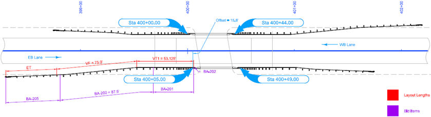
This is a 30 foot wide bridge. The bridge shoulders are narrower than the roadway shoulders. The approaching guardrail was laid out to place the head of the end terminals at least 2 feet outside the shoulder. The trailing guardrail was laid out to place post 3 of the end terminal outside of the length of need.

Example 2: Steel Beam Guardrail at a One Way Bridge (BA-250)
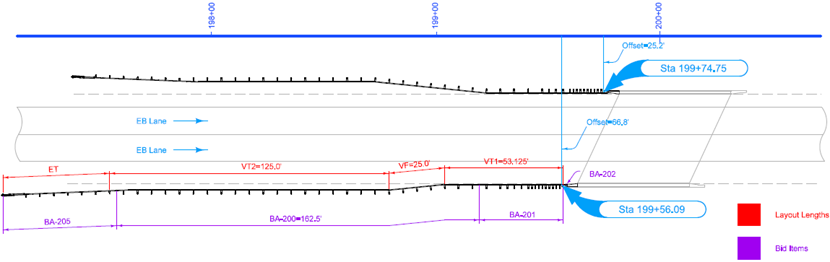
This is a 40 foot bridge on an expressway. The bridge shoulders are the same width as the roadway shoulders. For both outside and median installations, the guardrail was laid out to place VT2 at least 2 feet outside of the shoulder and to place the head of the terminals so that post 3 is outside of the length of need. The designer chose to use additional VF for the median side to reduce the length of the installation.

Example 3: Steel Beam Guardrail over a Low Fill Culvert (BA-210 and BA-251)
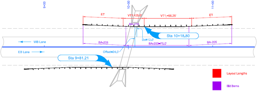
The fill over the culvert isn’t deep enough to allow full embedment of the posts, so BA-210 is used to connect the posts to the culvert. The guardrail was laid out to be a minimum of 2 feet outside of the shoulder. The approaching guardrail was laid out to place post 3 outside of the length of need. For both directions of traffic, the trailing guardrail is located in the clear zone for the opposing traffic, so BA-205 was used rather than BA-203.

Example 4: Side Obstacle Shielded with Steel Beam Guardrail (Two Way Protection) (BA-251)
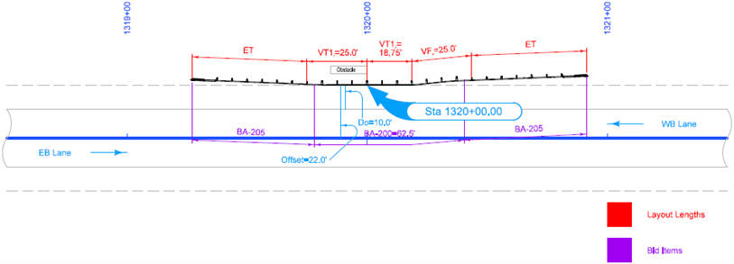
For this installation, the obstacle was located slightly less than 5 feet from the edge of shoulder. The installation was placed at the edge of the shoulder to maximize the allowable deflection for the guardrail. The approaching guardrail was laid out to place the head of the end terminals at least 2 feet outside the shoulder. For both directions of traffic, the trailing guardrail is located in the clear zone for the opposing traffic, so BA-205 was used rather than BA-203.

Example 5: Side Obstacle Shielded with Steel Beam Guardrail (One Way Protection) (BA-252)
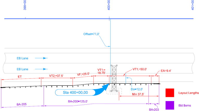
For this installation, the guardrail is located 2 feet from the edge of shoulder. The designer chose to use additional VF reduce the length of the installation. The trailing side is located outside of the clear zone for opposing traffic, so BA-203 was used to anchor the installation. The BA-203 was placed such that the last BCT post is located a minimum of 37.5 feet (25 feet of VT plus the 12.5 foot length of the BA-203) beyond the obstacle.

Example 6: Median Obstacle Shielded with High Tension Cable Guardrail (BA-351)
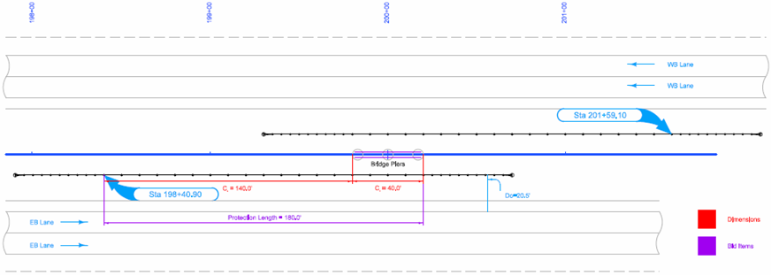
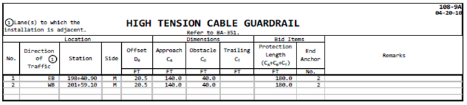
For this installation, the clear zone is measured out to the back side of the pier. The resulting length of need is 139 feet, so Ca is set at 140 feet (length of need rounded up to the next 10 foot increment).
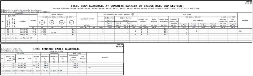
Example 7: High Tension Cable Guardrail Attached to Steel Beam Guardrail (Case 1) (BA-250 and BA-351)
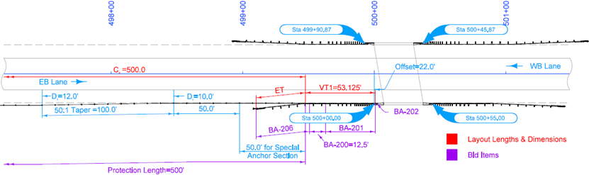
The installation of interest in this example is the W-beam to cable crossover. The BA-206 is a flared end terminal, so an additional 12.5 feet of VT is added on to the BA-201. A special anchor section is required to connect the high tension cable guardrail to the W-beam steel beam guardrail. This is assumed to be 50 feet. Starting 50 feet downstream from the special anchor section, the high tension cable is tapered out 2 feet to get it 2 feet off the edge of the shoulder. This moves the start of the high tension cable guardrail taper downstream from the assumed length of the special anchor section.
Example 8: High Tension Cable Guardrail Attached to Steel Beam Guardrail (Case 2) (BA-250 and BA-351)
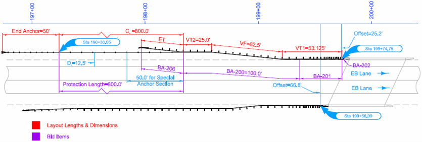
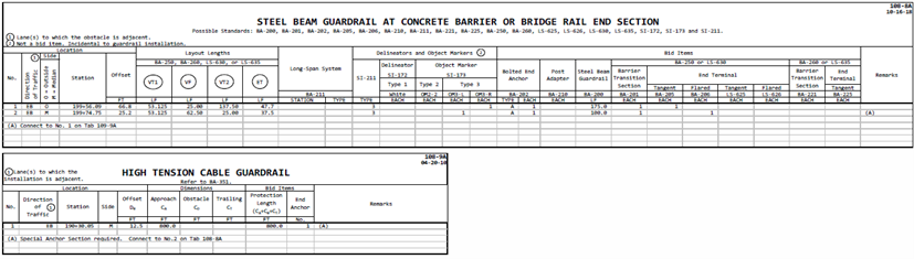
The installation of interest in this example is the W-beam to cable crossover. A special anchor section is required to connect the high tension cable guardrail to the W-beam steel beam guardrail. The high tension cable guardrail is placed to be at least 12 feet from the edge of traveled way. In order to do this, the designer used a combination of variable tangent and variable flare. A minimum of 25 feet of VT is required for the high tension cable guardrail to W-beam steel beam guardrail crossover, so a VT2 of 25 feet is used. Fifty feet of VF is used to place VT2 12 feet from the edge of traveled way. Because the BA-201 is connecting to VF, an extra 12.5 feet of VT is added to the BA-201, so VT1 is 53.125 feet.
Back to top