Content Information
On this page...
The purpose of an S2 event or work effort is to: 1) review the proposed alignment and grade for a project; and 2) identify and document all soils related items affecting ROW in order to allow for timely acquisition of ROW. This event typically includes preliminary design and definition of all stability berms, backslope benches, final borrow site selection, and other stability features that need additional ROW acquisition. In order to accomplish this, the drilling program typically needs to be established and performed for both the potential borrow sites and the alignment. A conceptual borrow design is developed for each borrow site that is selected for final use
An S2 is typically accomplished by evaluation of all available project and reference materials, including the S1 report, exploratory drilling, lab tests, and detailed geotechnical stability analysis.
Back to topReference Documents
Project inputs (documents) typically needed for initiation of an S2 work effort include, but are not limited to:
Proposed corridor/project limits.
Plan/profile sheets.
Project cross sections.
The borrow need and distribution as currently known or estimated.
Location of all structures (culverts, etc., and bridges if available).
Anticipated or possible project breaks (termini) as currently known.
S1 Event Report.
Reference materials researched and used as part of the S2 effort may also include:
- Previous project design.
- As-built plan information.
- Other material (i.e., LiDAR, soil surveys, GIS info, etc.) that may be beneficial.
S2 Event Scope
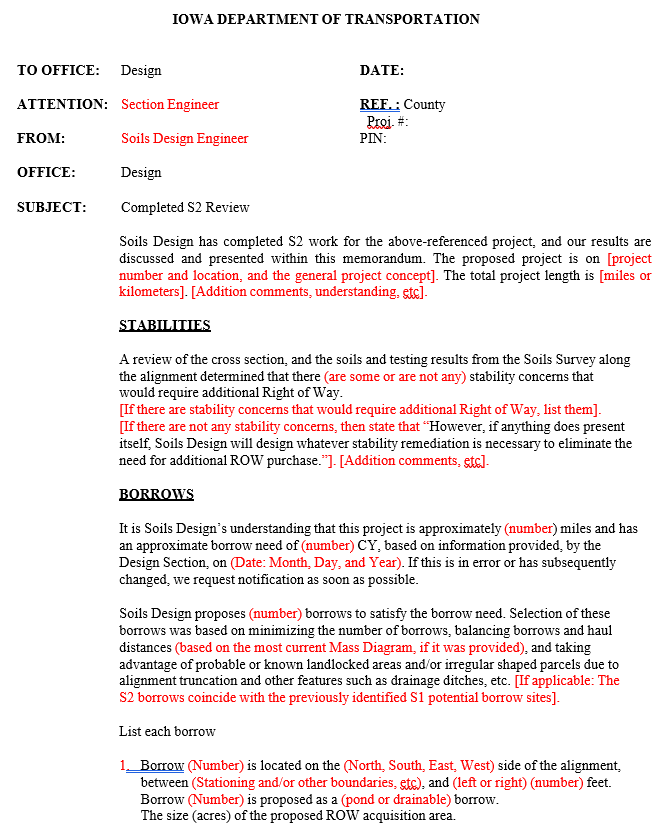
A written S2 submittal (i.e., memo) reports the findings of: 1) the stability evaluation identifying and documenting all soils related items affecting right of way and/or requiring more right of way for grading related projects, along with preliminary design of the stability features (stability berms, backslope benches, etc.); 2) the final borrow site selection(s) and accompanying conceptual borrow design(s); and 3) other items that are pertinent to additional ROW acquisition and/or subsequent project development that were discovered during the subsurface investigation and/or office portion of the S2 effort.

| Completion of the S2 requires that most of the roadway-related drilling be performed, which may require several months to complete. For drilling to start, the reference documents outlined above are needed as soon as possible after the Field Exam, after all necessary approvals are obtained, and after selection of the final alternate. Bridge borings are typically performed later than the roadway-related borings and after the receipt of the bridge Situation Plan. Also, while a final borrow site selection is normally possible with an S2 effort, under some circumstances the S2 borrows/borrow sites must be considered proposed rather than final, pending further review, discussion, developments, etc.
|
|---|
Subsurface Investigation
Note that parts of the overall subsurface investigation are necessary for, and directly used for, S2 purposes as discussed in this section. However, a large part of the overall subsurface investigation is also used later for S3, S4, and/or other purposes as listed below. The overall purpose of the subsurface investigation for a roadway project is to provide sufficient soils related information for the following:
Overall geotechnical design for the final roadway location, both horizontal and vertical.
Suitability of materials obtained from cuts, borrow, or channel changes for use in embankments.
Final geotechnical design of the roadway section, foreslopes, and backslopes, including possible geotechnical remediations, etc.
Identification of required subgrade treatment and determination of type of subgrade treatment.
Identification of select soil locations and quantities available.
Identification of areas where geotechnical features such as subsurface drains are needed, and associated final design of such features.
Final geotechnical design of embankments in the vicinity of structures (including around bridges, when used in conjunction with the bridge borings), based on adequate determination of strength and consolidation characteristics of the subsoils from tests on soil samples obtained with the borings.
Include the entire length of the project under consideration in the scope of the soils investigation. The field exploration should be performed as outlined in Section 200C-1. All information and all aspects of drilling as included in Section 200C-1 must be fully understood, and must be appropriately and fully carried forward into the subsurface investigation so that all requirements of the investigation are fulfilled. As such, part of the overall subsurface investigation program (drilling) may, when necessary and under certain circumstances, be delayed until after the drilling that is required for S2 purposes has been completed.
Back to topDesign of Stability Features
The plan/profile sheets and the cross sections along the alignment must be reviewed along with the soil boring logs and laboratory test data from the Soils Survey to identify all potential cut/fill slope stability issues which would require additional ROW. Once a critical area has been identified, a detailed stability analysis of the entire area must be performed using geotechnical software (such as GEO5, Slope/W, etc.) and/or other procedures to determine if the cut/fill slope is stable and whether a stability feature will be required to improve stability. Types of slope stability analyses include rotational slope failure, translational failure, irregular surfaces of sliding, and infinite slope failure. Special attention should be given to areas of the project where:
Fill heights are > 10 feet.
Backslope heights are > 25 feet.
Soft soil is present.
Possible stability features (remediations) that can be used for increasing the stability of embankment slopes include, but are not limited to:
Stability berms (such as 10H:1V bench slope, 3H:1V toe slope, minimum 3 feet in height).
Backslope benches (usually standard design).
Undercutting/replacement of soft subgrade soils, and/or ground improvements such as rammed aggregate piers, and/or staged construction or similar techniques.
Subsurface drains and/or similar drainage features.
Stability analyses should be performed as outlined in Section 200F-1 for both undrained (end-of-construction) and drained (long term) cases. Soil and groundwater properties, as well as assumptions used in the analyses, should be documented in the stability file for the project. Slopes should generally be designed to have:
Factor of Safety > 1.3 (undrained case).
Factor of Safety > 1.5 (long term case).
After completion of the slope stability analyses, the necessary stability-related geotechnical remediations that require additional ROW must be depicted/defined/delineated on plan/profile sheets and/or cross sections so that the Design Section, Survey/Photogrammetry, ROW Office, District Office, Office of Location and Environment, and others can clearly understand the additional stability related ROW requirements that are necessary for S2 purposes.
Final Borrow Site Selection
The S1 Event is reviewed and the final S2 borrow sites are based on some or all of the following considerations:
- Minimizing the number of borrows and land use impact.
- Total borrow need, including amounts needed for shrinkage and cushion.
- Distribution of the total borrow need (where it is needed on/along the project, which requires a mass diagram or equivalent for the Soils Design Section to best understand).
- Project breaks.
- Hauling distance (generally < 2 miles in any direction).
- Hauling barriers (rivers, etc.).
- A borrow site’s potential to produce select for subgrade treatment (this is not always accomplished).
- Use of landlocked parcels, irregular shaped parcels, or total acquisition parcels.
- Proximity to farmsteads, homesteads, lakes, parks, and other sensitive features.
- Avoidance of environmental/cultural sites and issues (wetlands, historical sites, etc.).
- Desired or needed borrow design (pond or drainable).
- Potential for integration of final design details with wetland mitigation sites.
- Restrictions such as the Loess Hills region, Century Farms, pipelines, etc.
After borrow site selection is completed, the recommended ROW acquisitions for those sites must be depicted/defined/delineated in some fashion, typically on air photos that can be related to the project’s alignment, so that the Design Section, Survey/Photogrammetry, ROW Office, District Office, Office of Location and Environment, and others can clearly understand the ROW acquisition areas for the selected S2 borrow sites. In addition to the air photos, an electronic file for referencing the design file is advantageous and provided if feasible.
Include a general (simplified) conceptual borrow design in the S2 submittal at this time so that all individuals noted above can visualize the basic borrow concept/design, and so that the basic borrow concept/design can be carried forward into the S3 Event: Final Determination of All Geotechnical Related Items Required for Grading Plans. This general/simplified conceptual design is typically shown on an aerial photo that can be related to the alignment. That depiction is usually not much more than a general shape and size for a pond and drainable borrow concept. However, some details may be provided for pond borrow concepts (such as deep versus shallow ends of the pond), and probable surface drainage directions for a drainable borrow are usually depicted by a few arrows.
Back to topS2 Event Submittals
Draft S2 Submittal
A draft S2 submittal is usually prepared for internal peer review and/or other purposes such as initial, pre-distribution review of unusual items with other sections or offices. The draft submittal consists of a memo following the S2 memo boiler plate and should include full and detailed information/delineation/documentation of: 1) all areas where there are stability problems that require additional ROW; 2) each final selected borrow site, with identifying boundaries, size (acreage), type of borrow, type of material available, and estimated quantities; and 3) any other pertinent information. Also included are other items that might have been identified during the field exploration program (such as cisterns). If stability analyses are performed, a calculation package that includes the assumptions, input parameters, and output should also be available for peer review. Use the following boiler plates for final submittals: 1) S2 email and 2) S2 memo.
The draft S2 submittal should first be submitted to others in the Soils Design Section who can provide peer review comments, and then to the Soils Design Section Engineer. Comments should be documented, discussed, and addressed in the final submittal. The overall Soils Design Section review team should ultimately include:
Soils Design Section Engineer,
Soils Design Section Assistant Engineer,
Soils Design Section Geologists, and
Others as applicable.
Final S2 Submittal
The Final S2 Submittal Memo (pdf) is placed in the S2 Submittal folder of the Soils folder of the Project Directory and an email (see S2 email) is sent to the recipient list below with links or electronic files of the Final S2 Submittal. For consultants, the Final S2 Submittal is forwarded via email or ftp. The S2 submittal should be directed to the Design Section Engineer, Soils Design Section, and District Engineer with copies to the following:
Office of Design Engineer, Office of Design Assistant Engineer – Development, Office of Design Assistant Engineer – Support.
Assistant District Engineer and District Construction Engineer.
Office Director of the Office of Location and Environment, Wetlands Section Supervisor, and Cultural/Historic Resource Team Leader.
Office Director of the Office of Right of Way, Right of Way Design Supervisor, and Right of Way Acquisition Team Leader.
Photogrammetry Engineer and Survey Supervisor.
Roadside Development Supervisor.
Office of Construction and Materials – Earthwork Field Engineer.
Design Section Assistant Engineer and Design Section Technician.
Assistant Soils Design Section Engineer and those others in Soils Design who worked on the S1 and/or S2.
Electronic Files
For internal Iowa DOT use, electronic files are copied to the project directory and links to the files are included in the email, see S2 email. Consultant generated electronic files will be submitted with final submittal via email or ftp. Electronic files should be developed according to Section 20B-71.
Electronic files for the S2 submittal should include and be named:
County# - 2 digits, Route# 3 digits, and Paren # - 3 digits_S2memo.pdf, S2 Submittal Memo
County# - 2 digits, Route# 3 digits, and Paren # - 3 digits_S2.kml, Google Earth
County# - 2 digits, Route# 3 digits, and Paren # - 3 digits _S2.sol, Microstation
- County# - 2 digits, Route# 3 digits, and Paren # - 3 digits _S2borrowXX.jpg, Aerial Photos
Back to top
S2 Email

Back to top
S2 Memo