
Content Information
On this page...
The purpose of an S4 Event is to provide and document to the Bridges and Structures Bureau all pertinent Soils Design information, evaluations, and recommendations for a bridge or other structure for use in final design of foundation and other applicable structure elements, and development of final bridge plans. Final completion and turn-in of all structure related soils work for bridges and similar projects typically includes, but may not be limited to, SPS sheets, Report of Bridge Soundings, and the Supplemental Report of Structure Soundings. The Supplemental Report should contain all necessary information and recommendations for type and design of foundations, settlement analysis, stability analysis, remediation(s) or other types of needed ground improvements, delays, and other items pertaining to soils related issues.
Back to topReference Documents
Project inputs (documents) frequently referenced for and/or typically needed for initiation of an S4 work effort include:
- Final corridor/project limits.
- Final Plan/profile sheets.
- Final project cross sections.
- Final location of all structures (culverts, and bridges).
- TS & L (Type, Size, and Location), also referred to as the Situation Plan.
- All applicable related final project information.
- Desired or anticipated foundation type.
- Allowable settlement or other design constraints.
- Applicable staging and/or pertinent information.
S4 Event Scope
The S4 Event requires that all necessary and appropriate geotechnical engineering analyses and design be performed and documented to evaluate a structure’s foundations as well as all slope stability and settlement factors related to or associated with that structure, plus all other soils related items that relate to the structure. This involves the structure itself, but also usually involves an adjacent roadway embankment and/or other feature including the approach embankment to a bridge and the roadway embankment around a culvert. Justification for all pertinent of the Soils Design Section’s information and recommendations related to the S4 Event including the assumptions, calculations, and computer program output used in the engineering analyses should be documented and saved in the project file. Templates for the S4 deliverables in XLS format can be downloaded by going to the Department’s Forms webpage and searching for Forms 610010E (Report of Structure Soundings) and 6100104E (Supplemental Report of Structure Soundings.
Back to topReport of Structure Soundings
The Report of Structure Soundings provides a tabular summary (which is the Soils Design Section’s boring log) of the subsurface conditions at each of the structure’s sounding, drill, dig, or core holes that may be performed as part of the geotechnical investigation for that structure and (as applicable) the adjacent roadway. These soundings sheets are prepared in the field by the Soils Design Section drillers at the time of drilling. This tabular summary (boring log) serves the same purpose as the written and graphic boring logs typically produced by geotechnical consultants. Information on the Report of Bridge Soundings includes basic project information such as:
- County.
- Route No.
- Township, Range, Section.
- Project No.
- Type and Size of Structure.
- Location of Structure (e.g., Bridge over Keg Creek).
- Station Location.
- Responsible Individual.
In addition, the Report of Structure Soundings (boring log) includes soil/rock information at each test hole location. The following information is contained on a Report of Structure Soundings:
- Test Hole Number.
- Station and Center Line Ordinate of the test hole (offset direction and distance).
- Surface Elevation of Test Hole (include benchmark in notes).
- Depth to Water in feet.
- Depth to Bottom of Layer.
- Layer Designation (A, B, C…).
- Description of Material in Layer (consistency/density, soil type).
Supplemental Report of Structure Soundings
The Supplemental Report of Structure Soundings provides the blow count and other applicable field and lab data for the soil borings, plus the Soils Design Section’s recommendations for, and a discussion of, the culvert or bridge foundation design. The Supplemental sheets are started in the field by the Soils Design Section drillers at the time of drilling and used by them to record SPT blow count and other sampling information. They are then added to, and finalized in, the office during the office portion of S4 work. Generally, all of the Soils Design Section’s recommendations will be provided on the bottom of the Supplemental Report of Structure Soundings. If additional room is required to present the recommendations in more detail, a separate Supplemental Recommendations page/sheet can be developed and attached as part of the Supplemental Report of Structure Soundings submittal.
Information and recommendations contained in the Supplemental Report typically includes, but is not limited to:
- Blow Count (including blow for the seat – first 6 inches, second and third 6 inches, and total of the second and third (the SPT “N” value) and other sampling information as noted above, and associated lab test results.
- Summary or discussion of subsurface conditions as may be necessary for clarity or other purposes with the recommendations presented. Such things as pictures of rock core, if available, may also be included.
- Summary of results, and discussion as needed, on slope stability.
- Summary of results, and discussion as needed, on settlement.
- Basic recommended foundation type (H-piles, pipe piles, drilled shafts, etc.), and anticipated foundation support stratum or conditions (friction only, end bearing, rock socket, etc.).
- Specific recommendations for foundations for bridges:
- Driven Piles
- Design parameters for each soil/rock bearing or support layer.
- Recommended LRFD Resistance Factors.
- Design tip elevations.
- Driving points (required?).
- Potential construction issues.
- For bridges over streams, input on scour elevation and variations from that shown on the Situation Plan.
- All other pertinent information, recommendations, etc.
- Driven Shafts
- Design parameters for each soil/rock bearing or support layer.
- Recommended LRFD Resistance Factors.
- Recommended construction methods, if discussion beyond that included in Standard Specifications is needed (for example, permanent casing).
- For bridges over streams, input on scour elevation and variations from that shown on Situation Plan.
- Spread Footings.
- Design parameters for each soil/rock bearing or support layer.
- Recommended LRFD Resistance Factors.
- Bearing capacity vs. settlement charts.
- Recommended construction methods, if discussion beyond that included in Standard Specifications is needed.
- For bridges over streams, input on scour elevation and variations from that shown on Situation Plan.
- Recommendations for load tests and demonstration piles/shafts.
- Estimated settlements for all culverts (precast and cast-in-place), which is used by other sections/offices to define the camber to be placed on the culverts.
- Settlement plate locations and settlement criteria (delay) for continuation of construction.
- Construction delay requirements for approach embankments as it relates to the structure.
- Working blankets, granular blankets, and/or other features.
Soil Profile Sheets (SPS Sheets)
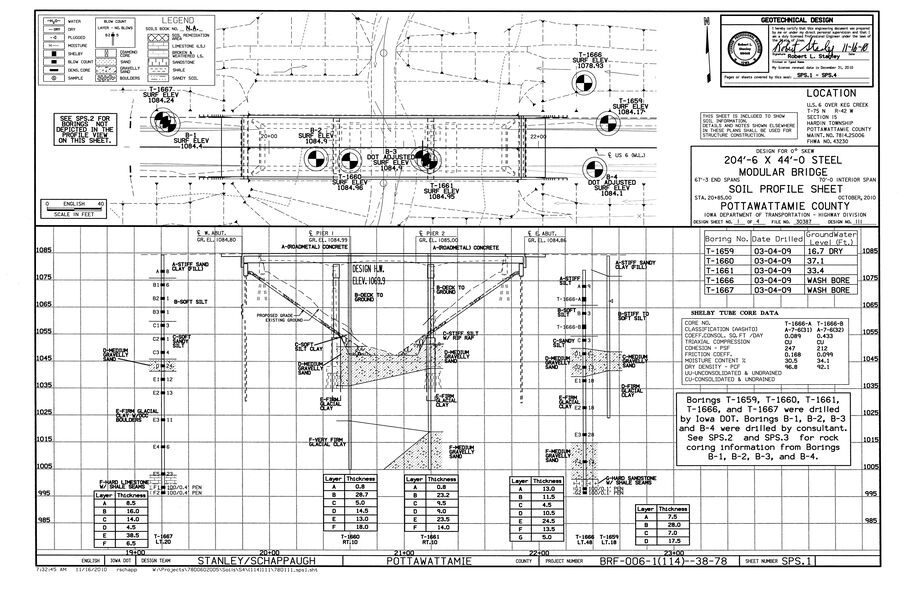
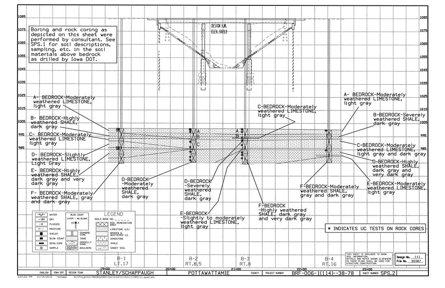
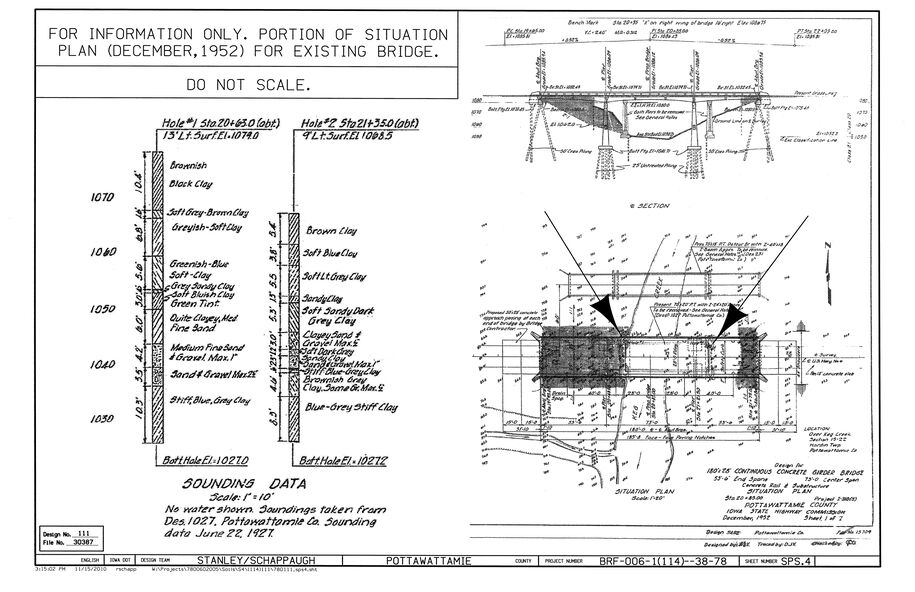
For bridge and culvert projects, one or more Soil Profile Sheets (SPS sheets) (see SPS Sheet Example, Pottawattamie6) are prepared and provided to the Bridges and Structures Bureau final design section by the Soils Design Section for inclusion in the final letting plans. The blow count sounding data and soil information should be plotted or shown on these sheets, including the depth of each layer and a description of the layer. Applicable and available laboratory test data is also included on the SPS sheet. If the soils information on the SPS sheets uses a station or offset or elevation reference or datum that is different than that used on the Situation Plan, full documentation and information or explanation relating to this should be included on the SPS sheets.
The SPS sheets should include, but are not limited to:
- Boring locations and numbers in plan view, with surface elevations of the borings, superimposed on the Situation Plan for the structure.
- Depiction of all applicable individual borings in profile view with stations and centerline offsets identified, along with the depiction of the structure in profile view.
- Subsurface profile between borings, with strata breaks, descriptions, and graphic representation.
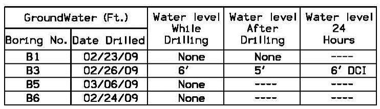
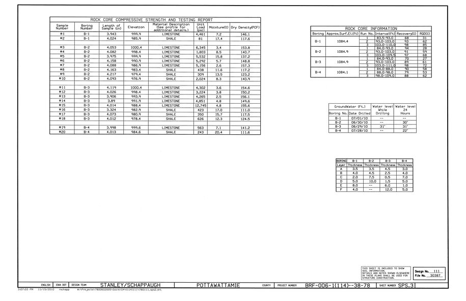
Groundwater information (Boring No./Date drilled/Water levels: while drilling/after drilling/at 24 hours, see example below).
- Split spoon/Shelby tube sample location and number.
- SPT “N” Values.
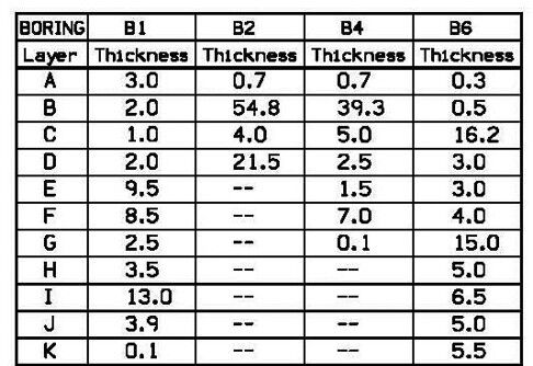
- Material layers, designations (A, B, C, etc., see example below) and thicknesses
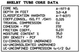
- Shelby tube core data (see example below).
- All rock core/coring information in profile view and/or in appropriate tables (Boring, Elevation, Run, Interval, Recovery, RQD, Moisture, Dry Density, see example below)

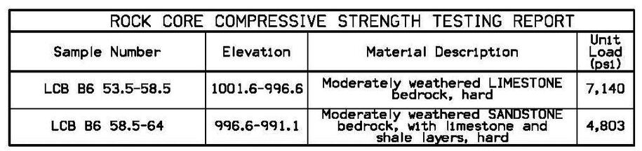
- Rock core compressive strength testing information from lab testing performed (Sample Number, Depth, Elevation, Material Description, Unit Load, Moisture, Density, see example below).
- Soil and sampling legend (see example below).
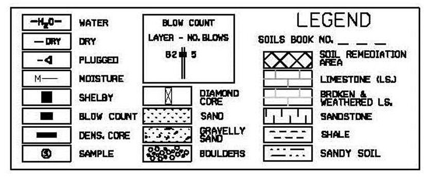
If geotechnical remedial measures such as wick drains, IFIs, core-outs, etc., were performed in a grading project prior to the current applicable bridge project, the outline/footprint and general description of that remediation needs to be shown on the SPS sheets so that the bridge contractor knows the history of the site and all prior work that has been done at the site.
Other items that may be included on the SPS Sheets (as needed or as applicable):
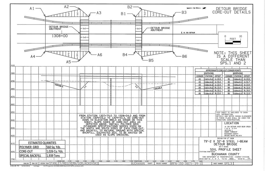
- Core-out limits (depth/width) required to meet post construction settlement, see Example (Buchanan150).
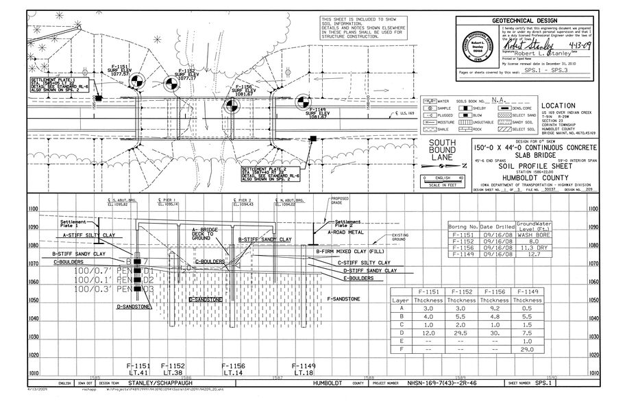
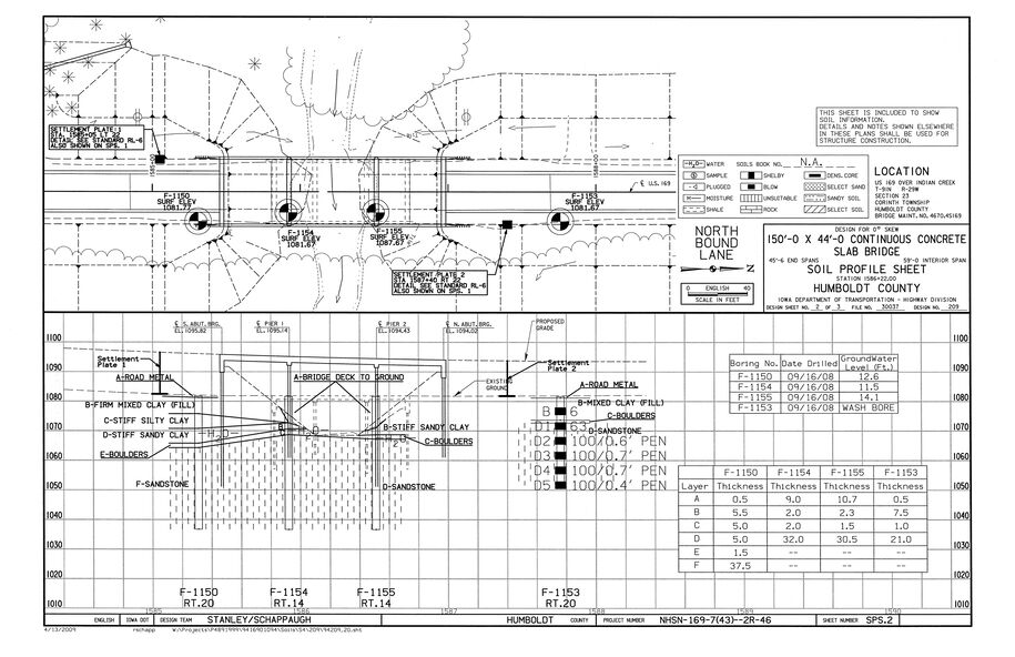
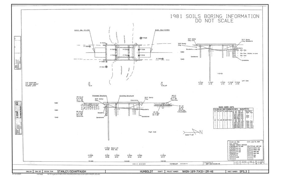
- Settlement Plate locations and applicable details, see Example (Humboldt169).
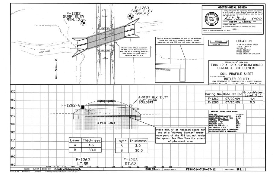
- Working Blanket or Granular Blanket limits (thickness/width), see Example (Butler14).
- Notes regarding existing structure conditions, if applicable and pertinent and not shown on other plan sheets (such as bridge plan sheets).
S4 Event Submittal
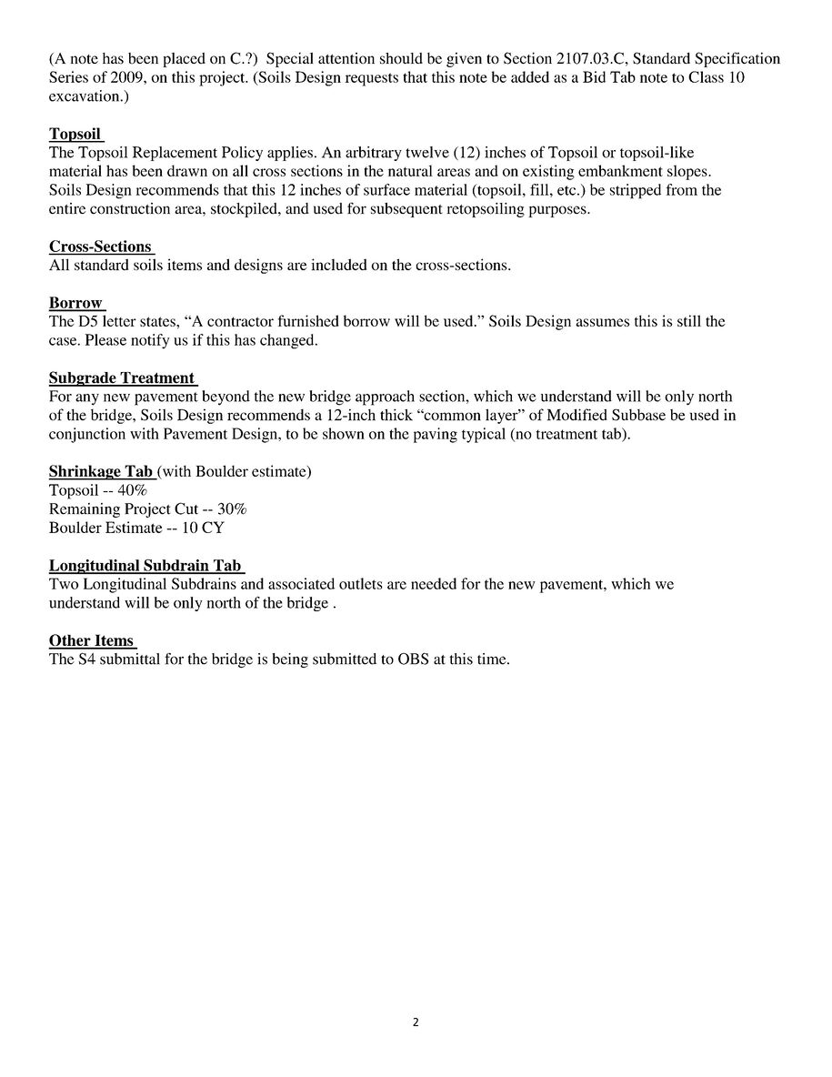
The S4 submittal includes an email (see S4 email, Sioux12) which summarizes everything that was completed as part of the S4 Event. It is sent to the recipient list below with links to the electronic files including: 1) SPS sheets; 2) Report of Structure Sounding(s); and 3) Supplemental Report of Structure Soundings, with recommendations as discussed previously. The S4 submittal should be submitted to the Project’s Bridges and Structures Bureau Section Engineer.
Copy the following:
Bridges and Structures Bureau Assistant Bridge Engineer.
Design Bureau Director, Design Bureau Assistant Engineer – Development, Design Bureau Assistant Engineer – Support.
Assistant District Engineer and District Construction Engineer.
Construction and Materials Bureau – Foundation Engineer.
Design Section Engineer.
Assistant Soils Design Section Engineer, and those others in the Soils Design Section that worked on the S4 Event.
Location and Environment Bureau.
In some instances, other offices may need to be copied.

| Document, and save in the project file, justification of all the Soils Design Section’s recommendations related to the S4 Event including the assumptions, calculations and computer program output used in the engineering analyses.
|
|---|
Back to top
Example Pottawattamie6
Back to top
Example (Buchanan150)
Back to top
Example (Humboldt169)
Back to top
Example (Butler14)
Back to top
Example (S4 email, Sioux12)

Back to top