
Content Information
On this page...
The purpose of an S3 Event or work effort is to complete all final soils related work for grading, grading related, paving, and similar projects including: all soils design sheets, tabulations of all final soils-related quantities, and other items that are needed for the letting plans. This is done as part of the overall final design of the project and includes everything pertaining to the Soils Design Section’s efforts and involvement on the project.
An S3 is typically accomplished by evaluation of all final project and reference materials, including the S1 and S2 reports, exploratory drilling, lab tests, etc., which are used to perform all necessary geotechnical analysis and design.

| The S3 submittal is in essence a part of the overall DM5 submittal. Design changes made by others during this event must be conveyed to the Soils Design Section in order to not delay this event |
|---|
Reference Documents
Project inputs (documents, etc.) typically needed for initiation of an S3 work effort include:
Final corridor/project limits.
Final plan/profile sheets.
Final project cross sections.
Final detailed borrow need and distribution.
Final location of all structures (i.e., culverts, bridges, walls, etc.).
Final project breaks (termini).
Boring logs/database.
Lab Test results.
S1 and S2 event reports and S4 event reports (if available/applicable).
Special mitigation needs.
All related final project information.
S3 Event Scope
The S3 Event requires completion of all soils/geotechnical engineering analyses and design discussed throughout this section. Justification for all the Soils Design Section’s recommendations related to the S3 Event, and especially the stabilities portion of the S3 Event, including the assumptions, calculations, and computer program output associated with the major engineering analyses, should be documented and saved in the project file. The S3 summary prepared for most projects reports the findings of the detailed geotechnical analysis, plus the recommended soils related construction requirements and operations/procedures necessary with construction of the project. The information contained in a S3 summary includes, but is not limited to the following: 1) final borrow design; 2) subgrade treatment; 3) moisture control; 4) shrinkage; 5) longitudinal subdrains; 6) backslope subdrains; 7) blankets and drains for stability purposes; 8) foreslope stability berms; 9) foreslope benches; 10) backslope benches; 11) bench cuts in rock; 12) settlement of foundation materials and structures; 13) settlement plates; 14) plowing and shaping; 15) topsoil; 16) boulders; 17) working blankets; 18) all other necessary subgrade and stability items; 19) soil usage lines on cross sections; 20) Q Sheets; and 21) CS Sheets.
|
| Justification of all the Soils Design Section’s recommendations related to the S3 Event including the assumptions, calculations, and computer program output associated with the major engineering analyses should be documented and saved in the project file. |
|---|
Final Borrow Design
Some of the final borrows could involve or require environmental enhancements (locally or statewide) beyond the normal pond or drainable design. The incorporation of environmental enhancements can be a matter of modifying the configuration (area and depth), taking advantage of the natural surroundings, and/or emphasizing the existing groundwater. For example, enhancements can be used to connect, restore, or create habitat areas. Where feasible, DOT borrow design will incorporate environmental enhancements such as accessible driveway and parking areas, shelter belts, snow catch areas, nesting areas or islands. Other enhancements could include the replacement of specific types of topsoil, appropriate seed planting (native grasses), hydrophytic plants, and the planting of grain foods and fruit trees. The incorporation of borrow design enhancements is usually accomplished by joint effort with Office of Location and Environment.
Pond Designs
Pond borrows have variable water depths (from less than 6 feet up to well over 25 feet), irregular bottoms, and irregular shorelines. When necessary, a pond borrow is designed with natural/maintenance-free overflow structures. Replacement of topsoil down to the estimated final water level is used to enhance habitat values. Slopes for the pond generally consist of a 6H:1V slope extending a minimum of 3 feet above and 3 to 5 feet below the projected water elevation, and 3H:1V in other areas. Shoreline stabilization (rip rap, etc.), as may be necessary, is incorporated into the design to reduce erosion. Pond borrow design as shown in Figures 1 and 2 should incorporate the following considerations:
- From natural ground intercept, extend a 3:1 slope down to a 6:1 beaching slope that has a vertical range from 3 ft above the estimated water level to 3-5 ft below the estimated water level, and to the bottom of the shelf. In some situations, the 6:1 beaching slope may start at existing ground and extend all the way down to the shallow depth shelf discussed below. If required by space or elevation constraints, the upper 3:1 slope can be difficult to design and can be omitted.
- Below the beaching slope, extend a 3:1 slope to the bottom of borrow.
- A shallow shelf to promote fish habitat should be incorporated in a typical pond borrow design. The shelf can be omitted if and only if the needed quantities from the borrow do not allow for the design of a shelf.
- As a general target, the shelf area should be approximately 10 percent of the total borrow area.
- The estimated depth of water in the shelf area should be no more than 6 feet.
- Potential overflow should be investigated and designed, if necessary, to avoid overflows onto any surrounding farm ground.
- Topsoil replacement down to the estimated water line is required.
- Minimum distance guidelines (exceptions may be possible):
- Edge of pond should be 50 feet from any adjoining property.
- Edge of pond should be 100 feet from any public right-of-way.
- Edge of pond should be 100 feet from the toe of the foreslope of an adjacent roadway.
- Edge of pond should be 100 feet from the centerline of an open district drainage ditch, or more if required (such as by the applicable Drainage District).
- Edge of pond may need to be 300 feet from the base of a levee, when excavated on the water (wet) side of a levee, depending on specific requirements.
- Edge of pond may need to be 500 feet from the base of a levee, when excavated on the land (dry) side of a levee, depending on specific requirements.
-
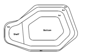
Figure 1: Example Pond Borrow Plan.

Figure 2: Example Pond Borrow Profile.
Drainable Borrows
Except for widened ditch or backslope borrows, drainable borrows (which are basically what the term implies), the primary goals of drainable borrow designs is to return the land to farming practices. This is quite frequently accomplished by design the borrow areas with farmable slopes ranging from 6H:1V to 10H:1V. Drainable borrows may sometimes result in different land use, such as enhancing wetland features. Drainable borrows as shown in Figures 3 and 4 are commonly designed to have either:
- A backslope at one end with a slope of 6H:1V (or flatter) and a bottom with around a 1 or 2 percent slope.
- Drainage either to a roadway ditch or natural/existing drainage system or a relatively flat design (cutting a knob or hill completely away).
- Iowa Code requires full topsoil replacement across the entire excavated area on essentially all drainable borrows (see Section 10A-1).
Minimum distance guidelines: Edge of borrow (limit of excavation) 50 feet from any adjoining property.
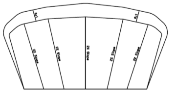
Figure 3: Example Drainable Borrow Plan.
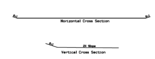
Figure 4: Example Drainable Borrow Profile.
Back to topSubgrade Treatments
The subgrade evaluation performed during the S3 Event must consider the short-term support of heavy construction equipment with minimum rutting, as well as the long-term support of the roadway pavement throughout the design life. Subgrade treatments are required everywhere. Short and long term stability of the subgrade may be affected by groundwater, sand/silt pockets, peat, and other unsuitable materials and/or conditions. Project subgrade treatments are influenced by:
Length (beginning and end station), width, and depth.
In-situ and available backfill materials.
Estimated shrinkage.
Quantities required to develop subgrades suitable for pavement support.
This information is tabulated on the CS sheets in Tab 103-3 and detailed on the Q sheets. The most common forms of subgrade treatment typically consist of either re-working and re-compacting existing select material if/when present at template cut level (adhering to the maximum thickness of soil layers that can be compacted), or else removal of unsuitable materials at template cut level and replacement with compacted select material. The select material used for subgrade treatment should consist of available on-site template cut or borrow material that meets select criteria (i.e., lean glacial clays, clean sand, possibly clean sands and gravels as allowed in the Iowa DOT Standard Specifications). However, if no suitable select material is available, the subgrade treatment typically consists of a 1 foot thick layer of Modified Subbase or Special Backfill. Geotextiles and geogrid, usually with a layer of granular material (and in combination with removal and replacement of non-select soil as needed) are also sometimes used for a subgrade treatment. Other possible forms of subgrade treatment may include the use of fly ash, cement, cement, kiln dust, or lime mixed with the in-situ soils and recompacted to provide suitable pavement subgrades. However, the Iowa DOT rarely uses these materials for design purposes.
The following items should be considered in designing and tabulating subgrade treatments:
Even though trench-width subgrade treatments are still shown in various typicals, etc., because they might be used by counties and other entities, Iowa DOT no longer uses trench-width subgrade treatments at any location, even if treatment material consists of purchased Special Backfill or Modified Subbase. All subgrade treatments on roadways included in Iowa DOT plans should be standard width.
The starting point for subgrade treatments is typically 2 feet of select glacial clay or select sand if available. This is increased to 2.5 feet if the overall project involves grading one year and paving the next year. Note that if select sand (sand that contains no more than 15% fines) is used for subgrade treatment, Special Backfill needs to be tabbed/used to roll into the surface of this sand subgrade treatment layer at a rate of 315 pounds per square yard in order to stabilize the surface from rutting and other surface disturbances. However, this may not be mandatory if the select sand contains enough coarser material within itself to be stable against rutting, etc., without the addition of Special Backfill.
Treatment thicknesses are increased to account for undesirable factors such as shallow groundwater, variable and/or primarily unsuitable soils directly underneath the treatment layer, etc.
If insufficient select soils are available for treatment, treatments usually consist of 1 foot of Special Backfill. One foot of Modified Subbase can be used instead of 1 foot of Special Backfill if/when the Soils Design Section and Pavement Design Section jointly decide to use Modified Subbase as a common layer or combined layer for both pavement design drainage purposes and soils design strength/support purposes.
Even if sufficient select soils are present, the Soils Design Section and the Pavement Design Section may for project specific reasons join forces and elect a combined/common layer of 1 foot of Modified Subbase to serve both soils design treatment/strength needs and pavement design drainage needs.
Geogrid can and is used to supplement subgrade treatment under certain circumstances.
All paved roads receive subgrade treatment. Sometimes gravel roads include a treatment layer. Lower volume paved county or city roads may receive a thinner treatment layer.
The following guidelines are commonly used by the Soils Design Section in the design of roadways. They should be evaluated for usage on each project as applicable and necessary. AASHTO M-145-91 and a classification based on 0.002 mm clay apply to these guidelines.
Select Soils
Situations may arise that necessitate the use of marginal select soils. The following variances to the select criteria may be considered as limiting.
Individual tests may be discarded if the majority of tests within the depositional horizon meet all requirements.
Providing all other criteria are met, the silt limit may be raised to 47%.
Providing all other criteria are met, the Proctor Density limit may be lowered to 108 pcf.
Providing all other criteria are met, the Plastic Index limit may be lowered to 8. This variance should not be used for deposits containing interbedded sand or silt.
Iowa DOT practice is that for cohesive soils, the sand and gravel percent should be less than 50%.
Subgrade Treatment Practices
The following guidelines should be used in areas where cut area subgrade treatment is required:
A minimum treatment of 2 feet of select soil or 1 foot of Special Backfill or Modified Subbase is required.
Nonuniform soils within 3 feet of subgrade top, particularly contact zones of major soil horizons and those soils containing pockets or interbedded layers of sand or silt, indicate potential frost heave areas. Treatments and/or drainage must assure that protection from ice lensing extends a minimum of 3 feet below subgrade.
A-4 soils with a Group Index of (7) or less have a high frost heave potential but are easily drainable. Treat as nonuniform soils within 3 feet of subgrade top and assure that the 3 feet of subgrade is well drained.
Subcut the bedrock cuts and treat with a minimum of 1 foot of suitable cohesive soil. Shale cuts should be treated full width with suitable cohesive soil. Treat all rock cuts requiring blasting with Special Backfill.
Drainage (subdrains or ditching) should assure that the ground water level is maintained at least 3 feet below finished subgrade. In areas where conditions are severe or where positive drainage cannot be assured, a minimum 1 foot of Special Backfill treatment should be used. In most cases, continuous longitudinal subdrains should be used.
In all urban designs, subcut the areas mentioned above and treat with 1 foot of Special Backfill. For areas not requiring treatments, place the upper 1 foot in the same manner as Special Compaction of Subgrade.
See the the Iowa DOT Standard Specifications for full details on treatments with Modified Subbase and/or Special Backfill.
Subgrade Treatment Moisture Control
Article 2102.03, D, 3, c, of the Standard Specifications requires all select soil placed for subgrade treatment purposes be compacted with moisture control. This applies to both cohesive and granular select soils.
Back to topMoisture Control
Moisture control is essentially a standard for all projects, except for minor projects that include no earthwork for pavement support. Moisture control limits for compaction are usually listed in Tab 103-6. This tab lists the moisture control limits as well as locations for the limits. The moisture control limits are determined by the Soils Design Section. Moisture and density control is not commonly used at the Iowa DOT.
Back to topUnsuitable Soils
In addition to the specifications for unsuitable soils as included in the Standard Specifications, the Soils Design Section almost always considers the following to be unsuitable soils:
Any soils with a Liquid Limit (LL) equal to or greater than 50.
Gumbo/gumbotil (considered Type B).
Claypan (considered Type B).
Residual clay (considered Type B).
Shale/clay shale is always considered unsuitable material and is almost always considered Type A.
Preferably, all unsuitable soils should be disposed of within a haul distance of ± 1 mile and all materials found on the project should be used. If disposal of excessive unsuitable soils becomes a problem, minor grade adjustments may be necessary to minimize the unsuitable soil cut. In such cases, suitable material will need to be obtained from borrows. With approval, excess Type B soils may be disposed of following the Type C criteria if the Type B disposal requirements cause the material to be wasted.
Back to topShrinkage/Swelling
Shrinkage is the percentage by which soil decreases in volume from its undisturbed volume prior to excavation to the final in place compacted volume when placed in an embankment. Swelling is the percentage by which rock increases in volume from its undisturbed volume prior to excavation to the final in place compacted volume when placed in an embankment. Shrinkage/swelling can be determined partly by comparing the densities of laboratory tests on in-situ and compacted embankment materials. However, this is only one part of overall shrinkage. Total shrinkage, as used at the Iowa DOT, also includes/encompasses a multitude of other factors, including, but not limited, to general loss of material during transport, wind and water erosion/loss, settlement/subsidence of an embankment as it is being built (see discussion above), and other items. Swelling should be considered when excavating hard rock that will be used to construct embankment fills.
Shrinkage data is included in Tab 103-7 on the CS sheets (see Section 1F-4.5). In general, the shrinkage factors for Iowa type soils are:
Back to topSubdrains for Fill or Foundation Drainage
Where fill induced settlement or stability may be a problem due to soft soil or high water tables, subdrains and/or trench drains, frequently in conjunction with granular blankets, need to be installed to drain the water. These devices are installed underneath the roadway, typically at the base of the fill or in the natural ground. Additional drawings and other related material are typically included within the contract documents to show locations and additional drain information. Examples of this procedure are located on Standard Road Plan DR-301. Fill and foundation subdrains are tabulated in Tab 104-5C.
Back to topLongitudinal Subdrains (Shoulder)
When the depth of a cut section for a roadway encounters ground water, it typically results not only in detrimental effects on pavement performance and life, but can also contribute to cut instability, localized sloughing of the foreslope and backslope, and potential slope instability and/or failure over the long term. Therefore, special attention must be given to groundwater during all phases of S3 work, plus S4 and other soils related work.
Longitudinal subdrains/shoulder drains are used not only for the above purpose but also to improve subgrade stability in conjunction with the subgrade treatment. Fin drains are similar to longitudinal drains and can be used as a substitute for conventional longitudinal subdrains in special cases where highly erodible loess (i.e., potential for piping) or rock is encountered at the pavement edge. Fin drains are installed using a large diameter cutting wheel that cuts a 4 inch wide trench for drain installation.
Longitudinal subdrains/shoulder/fin drains are installed at the pavement edge to remove water that accumulates under the pavement, and are detailed on Standard Road Plan DR-303. Longitudinal subdrains/shoulder drains are no longer depicted/shown on the design Q sheets, but they are tabulated on Tab 104-9.
Back to topBackslope Subdrains
Backslope drains are used in areas where groundwater seepage and/or a slide are possible on a backslope. Where water is perched on a very dense layer or within a sand pocket, a backslope subdrain is installed at a level where the seepage is intercepted by the drain (typically below the surface of the very dense or clay confining layer). Maintaining positive drainage (i.e., the flow line) is required to adequately remove the accumulated water. Backslope drains are depicted/shown on the design Q sheets and tabulated on Tab 104-9. For typical backslope subdrain configurations associated with roadway projects, refer to Standard Road Plan DR-303.
However, for clarification, backslope drains and their outlets are shown on the Q sheets in both plan and profile view (and are tabulated on the referenced tabulation, although this may change soon), plus backslope drains and their outlets are shown on the project cross sections. Basically, the true design of backslope drains is on the cross sections.
Back to topCore Outs
Core outs are one type of remediation that is used in areas where soft compressible materials are encountered and which will affect the overall embankment stability or settlement. In construction of the core out, the unsuitable materials are removed to a specified depth, as determined by the Soils Design Section, and the excavation subsequently backfilled with sand or select glacial clay, or occasionally with Class 10 material. Typically, drains are not incorporated in core outs. If the core out extends below the water table, outlets should be constructed in the core out to allow for dissipation of pore water pressures and free fluctuation of the water level.
Back to topOther Blankets and Subgrade Drains for Stability Purposes
The need for, design of, and location of other blankets and subgrade drains are determined by the Soils Design Section. The following outlines the most typical blankets and subgrade drains.
Working Blankets: A working blanket is required when the foundation materials are too unstable due to relatively high water levels and/or too soft to support construction traffic. The working blanket is typically constructed of sand at a minimum thickness of 1 foot. The location and extent of the working blanket is determined by the Soils Design Section; however, the blanket location can be adjusted or deleted during construction if the subgrade stability is suitable to support construction traffic. The edges of the working blanket should be left open to allow for drainage.
Shale-Contact Sand Blanket: Although not very common, a sand blanket or stone key may be used when shale is encountered to provide an increase in the frictional resistance between the shale and the Class 10 fill and improve stability. If soft, highly weathered shale is exposed, this material should be removed prior to placement of the sand blanket. It should also be noted that placement of fill on inclined shale surfaces has the potential for instability.
Granular Blanket Subdrains: Subdrains can also be used with granular blankets to develop a drainage layer in areas where the soil has a high moisture content and poor stability. These subdrains are usually installed in blankets where water seepage would accumulate (low points) or where the groundwater level is above the bottom of the blanket, and ponding of the water will result in instability.
Back to topForeslope Stability Berms
If potential instability of the planned roadway embankment slopes is determined from slope stability analysis (see Section 200F-1), stability berms (or other stabilization techniques) are necessary to stabilize foreslopes. Stability berms, due to their mass, provide additional resistance to potential slope movement. Foreslope stability berm configuration is determined by the Soils Design Section during the overall slope stability review and design process. The general stability foreslope berm configurations are included in Section 3J-1.
Back to topSliver Fills and Foreslope Benching
Foreslope bench cuts provide interlocking of sliver embankment fills with the subgrade. Bench cuts are generally required for fills placed on existing grades that have a slope of 3H:1V or steeper and are more than 10 feet in height. Typical bench cut criteria for sliver fills is outlined in Article 2107.03 of the Standard Specifications and should be constructed with a step or series of steps cut on approximate horizontal plane(s) with vertical slope cut dimensions of no less than 3 feet. These sliver fill benches do not need to be shown on the Q sheets and cross sections since their requirement is covered by the Standard Specifications.
Besides the common sliver fill benches as discussed above, benching of foreslopes that can be considered above and beyond the sliver fill benches are frequently required for slope stability purposes in multiple instances. Any potential sliding surfaces (previous slip planes, buried vegetation, etc.) should be investigated and addressed by benching as necessary. The need for, design of, and location of these benches are determined by the Soils Design Section, and unlike sliver fill benching, must be shown on the Q sheets and project cross sections. The general foreslope bench configurations are included in Section 3J-1.
Back to topBackslope Benches
If potential instability of the planned roadway backslopes is determined from the slope stability analysis (see Section 200F-1) performed during the stability review and design process, backslope benches are commonly used to improve backslope stability in areas of deep cuts (typically > 25 feet). The need for backslope benches should ultimately be defined by the Soils Design Section. The general backslope bench configurations are described in Section 3J-1 with typical configurations outlined in Design Details 4104 and 4107. The Roadway Design Section should automatically put backslope benches on the cross sections before they are available to the Soils Design Section, but those should be reviewed by the Soils Design Section and modified or added to as necessary.
Back to topBench Cuts in Rock
Depending on the planned roadway elevation, areas along the alignment may require cuts through bedrock. Rock slopes are generally project specific and should be designed in a joint effort between the Design Section and the Soils Design Section as outlined in Section 200F-8. Typical design details for rock slopes can be found in Design Details 4107, 4110, and 4111.
Back to topSettlement of Foundation Materials and Structures
The serviceability and functionality of a roadway embankment (especially around stationary items such as a bridge abutment) and associated roadway structures should be evaluated for estimated embankment settlement. In general, settlement within and at the surface of an embankment can result from consolidation of the foundation soil due to the weight of the overlying embankment fill soils and densification/consolidation of the embankment fill soils themselves (e.g., due to wetting induced compression, etc.). Settlements should be evaluated to determine if ground improvement, paving delays, or approach slabs are justified, or if the estimated post construction settlement is sufficiently low to proceed with final paving or construction. Settlement prediction methods are shown in Section 200F-2.
Include details, design, etc. for wick drains (Section 200F-7), intermediate foundation improvements (Section 200F-6), reinforced steepened slopes (RSSs), etc. in the S3 submittals.
Back to topSettlement Plates
If a paving or construction delay is anticipated or necessary, settlement plates should be installed and monitored to determine when construction can continue. The settlement plate details and specifications can be found on Standard Road Plan EW-212 and in Section 2106 of the Standard Specifications. The number and location of the settlement plates will be tabulated in Tab 103-5 and shown on the CS sheets and Q sheets. Even though settlement plates are typically installed by the grader during the grading portion of a project, settlement plates that are associated with bridges and structures, as most are, are also depicted on the SPS sheets in the S4 submittal for the bridge contractor’s information.
Back to topPlowing and Shaping
Plowing and shaping is frequently a necessary construction procedure for building a new embankment in situations where the new pavement is positioned partly but not totally directly over an existing embankment. The reasoning behind plowing and shaping is to provide uniform pavement support across the width of the new pavement, as opposed to pavement support partly on old/existing fill and partly on new fill material. Materials excavated in rebuilding the embankments can generally be redeposited in the same general construction area or any adjacent embankment, provided the materials meet the project specifications and are approved by the Soils Design Section. Standard Road Plan EW-101 provides a detailed cross section for the depths and limits of excavation as part of plowing and shaping. The locations requiring plowing and shaping are included in Tab 107-31 on the CS sheets.
Back to topTopsoil
Section 10A-1 will generally apply to all projects. The Soils Design Section usually marks the topsoil on the project cross sections, and the roadway Design Section usually does all other plan work related to topsoil. The quantities of topsoil removal from borrows, cuts, or areas to be covered by embankments, and the depositing and spreading of the topsoil on shoulders, slopes, excavated areas, borrows, and other designated areas, should be quantified by the roadway Design Section, and may be based partially on input provided by the Soils Design Section. The quantity and location of topsoil excavation should be identified and tabulated by the Design Section on Tab 103-10. Topsoil should be placed in the areas designated on Tab 103-10 and spread uniformly over the area to be covered, smoothed, and left in a finished condition so that it will drain properly.
Back to topBoulders
Boulders encountered in the subsurface exploration or anticipated in excavations should be identified on the Q Sheets. A boulder estimate should be included on the shrinkage tab on the CS sheets, Tab 103-7. Boulders are defined as rocks or pieces of rock greater than 6 inches in diameter. If the boulders are used in embankment construction, they must be used as allowed by Section 2102 the Standard Specifications. Large boulders that cannot be placed as outlined above may sometimes be used with approval of the Soils Design Section and/or others. Note that Class 12 Boulders do not include rock material generated by rock excavation, which is a Class 12 Rock Excavation item.
Back to topS3 Event Submittal
The S3 submittal includes an email (see S3 email) which summarizes and details everything that was completed as part of the S3 event. This is sent to the recipient list below with links to the electronic files including: Cross Sections, CS, and Q Sheets, plus any other item that may be a part of the S3 work and submittal. For consultants, the S3 submittal should be transmitted according to information provided in the Consultant Specifications, the contract documents, or otherwise. The S3 submittal should be directed to the Project’s Design Section Engineer and the District Engineer.
Copy the following:
- Office of Design Engineer, Office of Design Assistant Engineer – Development, Office of Design Assistant Engineer – Support.
- Assistant District Engineer and District Construction Engineer.
- Office Director of the Office of Location and Environment, Wetlands Section Supervisor, and Lead Cultural Resource Manager.
- Office Director of the Office of Right of Way, Right of Way Design Supervisor, and Right of Way Acquisition Team Leader.
- Photogrammetry Engineer and Survey Supervisor.
- Road Side Development Supervisor.
- Office of Construction and Materials – Earthwork Field Engineer.
- Design Section Assistant Engineer and Design Section Technician.
- Assistant Soils Design Section Engineer and Geologist, and those others in the Soils Design Section that worked on the S2.
The sheets developed by the Soils Design Section and included as part of the S3 submittal should include the information summarized below.
Q Sheets – Subsurface Investigation Soils Plan and Profile Sheets
All Boring Locations are shown in plan view.
Subsurface Profile (basically a boring-to-boring profile that generally follows or mimics project centerline) with strata breaks (i.e., do not connect bottom of borings) and descriptions.
Identification of select soils, unsuitable soils, rock, etc. (hatching/patterns).
Bar graphs (unsuitable materials, rock excavation, and waste).
Water levels (24 hours, dry, plugged).
Shelby Tube Core Data, Sample Data, All Lab Data, etc. (e.g., Density, Cut Moisture, Plastic Limit).
Subgrade Treatments (if treating with select from template cut).
Soil Remediations (wick drains, intermediate foundation improvement).
Incorporation of all stability items (benches, berms, drainage or stability blankets, working blankets, various types of drains and drain systems, etc.).
Instrumentation (settlement plates, piezometers, etc.).
Soil Legend and Information Sheet (this is usually the Q.1 sheet).
Sliver fill note, if needed.
Cross Sections
Identify select and unsuitable soils, rock, and other soil usage delineations.
All soil borings, or at a minimum, the borings not depicted on the profile sheets.
Incorporation of all stability items (benches, berms, blankets, drains, etc.)
CS Sheets – Tabulations
Subgrade Treatment Tab (103-3).
Longitudinal Subdrain Shoulder and Backslope Tab (104-9).
Shrinkage Tab (103-7).
Embankment with Moisture and Density Control or Embankment with Moisture Control Tab (103-1, 103-6).
Plowing and Shaping Tab (107-31).
Stability/Constructability Related Blankets and Drainage Tab (104-5C).
Wick Drains (WSD-1) (Station Range of the field).
Removal of existing subdrains (RLS-1)
Settlement Plates Tab, if necessary (103-5).
Electronic Files
For internal Iowa DOT use, electronic files are created, edited, and stored in the project directory. Consultant generated electronic files will be submitted with final submittal via email or ftp. Electronic files should be developed according to Section 20B-71.
Electronic files for the S3 submittal should include and be named:
Excel: County# - 2 digits, Route# 3 digits, and Paren # - 3 digits_CS1.xlms
PDF: County# - 2 digits, Route# 3 digits, and Paren # - 3 digits_VanDike.pdf
Microstation: County# - 2 digits, Route# 3 digits, and Paren # - 3 digits _.sol
Microstation: County# - 2 digits, Route# 3 digits, and Paren # - 3 digits _Q1.sht
Microstation: County# - 2 digits, Route# 3 digits, and Paren # - 3 digits _BorrowLetter.tin
Microstation: County# - 2 digits, Route# 3 digits, and Paren # - 3 digits _BorrowLetter.xml