
Content Information
On this page...
For the purpose of this section, the term “landslide” refers to the movement of soil, rock, and/or earthen debris down a slope, which can also be called a “slope failure” (Turner and Shuster, 1996). Since each landslide is unique and results from a combination of factors, historic data has been used by the Soils Design Section to understand trends of landslide development with respect to engineering characteristics of the soils and rocks, topography, hydrology, and other factors involved in slides.
This section addresses the typical modes of landslides in Iowa, approach of analysis, and slope instability mitigation techniques used by the Soils Design Section.
Back to topCauses of Landslides in Iowa
Landslides result from several causes, or a combination thereof, including geological, morphological, physical, or human influence. However, for a landslide to occur, it must be triggered by an external event. An event such as intense rainfall, flooding, or stream erosion may result in a near immediate slope instability. On the other hand, an event such as weathering of material may gradually result in slope instability over a much longer period of time. Based on the historical Iowa data, the majority of slope failures are a result of change in groundwater levels, groundwater seepage, or other water sources.
Slope Height and Inclination
Slope geometry affects stability in terms of height, slope angle, and cross section. High steep slopes are more likely to fail than low gentle angle slopes. Based on the historical data in Iowa, slopes constructed flatter than 3H:1V and slopes with heights of less than 10 feet typically have small potential for instability (Lohnes, et al., 2001) unless a feature such as an improperly filled utility line trench is present on or just above the slope.
Groundwater Levels, Precipitation, and Water Seepage
Varying groundwater levels, precipitation events, and water seepage from other sources are major contributors to slope instability. Changes in the groundwater levels can result in a reduction of shear strength and softening of the slope materials, which in turn can result in slope failures along these softened materials. Soils design experience indicates that water seepage or changes in groundwater levels is typically a significant component in development of landslides in Iowa.
Geological Influence
The engineering properties (shear strength and unit weight) of soil and rock will influence the stability of slopes. These properties may vary with soil and rock deposits and with depth in each strata and geologic origin. Particular attention should be given to shale that is exposed in cuts and to paleosols with high clay content. These types of rock soil formations are prone to sliding block failures along the very low strength weathered shale or paleosol surface. Slopes constructed with or on soils with low shear strengths and high unit weights are more likely to have slope instability. For instance, paleosols with high clay content and shales that are exposed to weathering are two materials that may be especially vulnerable to slope instability.
Construction/Maintenance Activities
Construction and maintenance activities may result in modifying drainage and loading the top of slope (e.g., fill placement, temporary soil stockpiles, or removing soil from the toe of the slope (e.g., deepening of ditches)). In addition, removal of trees and improperly filled utility line trenches may contribute to slope instability. These activities either increase the driving force (fill placement) or reduce the driving resistance (removal of toe material), as well as allow introduction of water into the slope, which may result in slope instability.
Back to topModes of Landslides
Types of movement most observed in Iowa include: topples/falls; translational; rotational; and flows.
Topple/Fall
Topples and falls are distinguished by an abrupt movement of materials, soil and/or rock, that are displaced from near vertical or steep geologic formations. Topples occur on nearly vertical slope where the top material rotates outward and falls, see Figure 1.
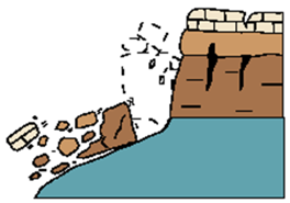
Figure 1: Topple (from USGS).
In Iowa, topples are likely in areas where a harder rock formation (e.g., limestone) overlies a softer rock formation (e.g., shale and some sandstones) that is susceptible to weathering. As the softer rock formation weathers, it may undercut the upper harder formation leaving the upper rock ledge unsupported. If the weight of the rock is greater than the tensile resistance of the rock, the block of rock will rotate forward and topple.
Rock falls, see Figure 2, are typically associated with two mechanisms: 1) the removal of material by outside/erosion forces; or 2) forces induced into soil/rock slope geometry by water and weather.
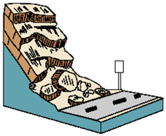
Figure 2: Rock fall (from USGS).
An example of the first mechanism would be a stream that undercuts and erodes material from the outer bend of a meandering stream, and as the material is eroded, the stream bank materials progressively fall into the moving water. The second mechanism would include rock falls that have developed from water entering cracks in the formation and then freezing and expanding. As the water expands, it breaks apart the rock formation.
Translational Movement
Translational slides involve movement of material down slope and essentially parallel to the original slope surface, see Figure 3.
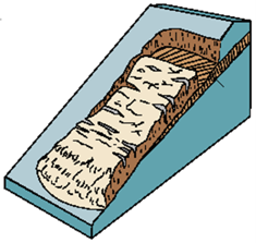
Figure 3: Translational slide (from USGS).
In many cases, translational slides are shallow surficial failures or occur at the contact between two varying materials. This type of failure is common where weathered shale is encountered near the surface, and especially when the top of the shale is sloping.
Block slides are translational slides that include movement of a single mass (i.e., a rock block). Block slides most commonly develop in sloping bedrock formations, where a bedrock block tends to slide downward along a parallel failure plane.
Rotational Movement
The movement of rotational slides typically includes large downward displacements near the top of the slide (an observable scarp) and upward displacements at the bottom of the slide (an observable bulge), see Figure 4. The failure generally occurs on an almost circular failure surface. The failure surface of a rotational slide is generally deeper than that of a translational slide.
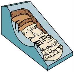
Figure 4: Rotational slide (from USGS).
Flow
Flows, see Figure 5, are the downslope movement of a loose soil or rock slurry typically caused by intense surface water flow, heavy precipitation, or rapid snowmelt. This type of failure mode can occur during high intensity rain events where the soil has a very high void ratio, such as in friable loess (Lohnes, 2001).
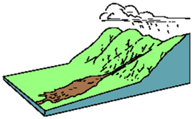
Figure 5: Soil/rock flow (from USGS).
Back to topAnalysis of Landslides
Slope stability analyses can also be used to evaluate slopes that have experienced distress (slopes that have failed) by assessing potential slope failure mechanisms through back analysis. All slope stability analyses should be performed as outlined in Section 200F-1. These same analyses can then be used in the design of mitigation techniques to repair the failure. However, before an analysis of a failed slope can be conducted, several questions need to be answered (from Lohnes, et al., 2001):
- Is long term or short term stability more critical?
- What is the configuration of the failure surface?
- What is the subsurface profile? Are discontinuities present in the soil strata?
- What is an appropriate safety factor?
- Is the observed failure a new or reactivated slide?
- Are the appropriate soil strength parameters and unit weight conditions known?
- What are the groundwater levels?
- Was any water seepage observed within or adjacent to the failed slope?
Long Term or Short Term Stability
The slope/loading condition (during construction or long term) when the failure occurred will influence the selection of appropriate soil strength parameters.
Configuration of Failure Surface
Observing the shape of the slide failure surface can provide information on why the slope instability occurred and the type of analyses that may be required for development of remedial measures. Depending on the slope failure surface configuration, a combination of circular, user defined, and block type failure analysis may be required in the back analysis to determine existing shear strengths.
Soil/Rock Discontinuities
Geologic discontinuities such as contacts between different soil and rock types can provide potential planes of weakness that may influence the stability of a slope (Lohnes, et al., 2001). Common geologic contacts that influence slope stability in Iowa include: loess/glacial till interfaces that may contain perched water; tension cracks in near-vertical or deep loess cuts; deep erosional cuts in glacial till; and sloping shale surfaces.
Appropriate Factor of Safety
Depending on the reliability of the soil/rock data, uncertainty, consequences of failure, and potential future slope movement, an appropriate factor of safety should be assigned to the analyses. If the subsurface conditions have been well defined (appropriate number of field and laboratory test to define shear strength), a lower factor of safety could be used over the condition where the subsurface conditions have not been well defined (limited amount of field/laboratory testing). The minimum design factors of safety for different cases are outlined in Section 200F-1.
Slide History
If based on the site observations it appears that the slide may have been reactivated along a pre-existing failure surface, residual or fully softened strength parameters should be used in the back analyses.
Soil Engineering Properties
Soil slope design relies on the strength and behavior of the soil that is obtained during the subsurface exploration and laboratory testing, as well as estimated parameters obtained from back analysis. In addition, the ground water conditions must be fully characterized as part of the analysis process. As indicated previously, the slope/loading condition (during construction or long term) when the failure occurred will influence the selection of appropriate soil strength parameters. Section 200E-1 provides a more detailed discussion on the selection of drained (long term) and undrained (during construction) soil shear strength parameters, and the differences in total and effective stress. In general, total stress parameters are used in materials where the pore pressure increases with the application of load (fine grained soil), and effective stress parameters are used in materials were loading does not produce a change in pore pressure (coarse grained material).
Back to topMethods of Repair
Most landslide repairs can be broken down into four components for discussion of repair of different types of landslides: geometric; materials; earthwork; and drainage. The following techniques, which are documented in Lohnes, et. al., 2001, have been successfully used by the Soils Design Section.
Geometric Components
One of the easiest unstable slope repair methods is to flatten the slope angle as shown in Figure 6. However, this method of repair may have significant impact on the amount of right-of-way (ROW) required for construction of foreslopes and backslopes.
Stability berms, also called toe berms, can also be used to stabilize foreslopes by increasing the toe resistance, Figure 6. This option method also impacts ROW, but sometimes to a lesser extent than simple slope flattening. Stability berms, due to their mass, provide additional resistance to potential slope movement. Foreslope stability berm configuration is determined by the Soils Design Section during the slope stability analysis of the unstable slope. The general stability foreslope berm configurations are included in Section 3J-1.
Backslope benches, which may in general be thought of as analogous to stability berms, achieve the same goal as flattening, but sometimes with less ROW impact. The width and location of the backslope bench should be designed in a joint effort between the Design squad and the Soils Design Section. The general backslope bench configurations are described in Section 3J-1 with typical configurations outlined in Design Details 4104 and 4107.
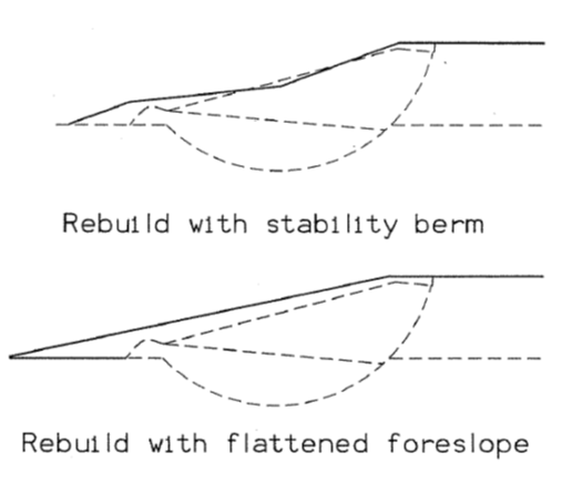
Figure 6: Slope repairs using geometric components (from Lohnes, et. al., 2001).
Earthwork
Excavation is usually required with rebuilding a slope, especially in benching before fill placement or in removal of unsuitable materials. Extreme care should be exercised when performing excavation on or near the toe of a failed slope so as not to further destabilize the slope. Excavation can also be part of a solution, as in re-channeling a stream that is eroding a slope, or realigning ditches.
Benches should be constructed before placing new fill at a failed slope. This is accomplished by excavating a minimum flat 5 to 6 foot wide bench (W). The exposed cut face (Y) is then excavated to heights of 3 to 10 feet at 1H:1V slope, and another bench is constructed. Bench widths and heights should be adjusted based on field conditions at the time of construction, but benches generally run horizontally through the length of a slide-repair (benches usually do not slope longitudinally). This procedure interlocks the new fill with the existing slope and reduces the chance for a shallow failure at the interface of these two materials, as shown in Design Detail 4320.
Benching need not and probably should not be performed all at once, but rather just in advance of new fill placement. This benching operation should be performed for any fill placed on ground sloping steeper than about 4H:1V.
All suitable earth materials used to rebuild a slope should be at or close to optimum moisture content, and should be appropriately compacted with moisture control. Larger materials like riprap are not compacted. When rebuilding a slope, the placement of new fill should begin at the toe and progress upward. Heavy equipment should be kept on the toe side of the repair whenever possible. Equipment should not be placed at the top of the slope, as this may further exacerbate the situation.
Drainage
Internal longitudinal drains are typically incorporated in rebuilt foreslopes with a known or suspected water problem. The type and number of drains will depend on the extent of the water problem and the resources and equipment available. The flat benches formed during reconstruction are frequently used as a platform for drain installation.
Backslope drains are generally similar to longitudinal drains and are used in backslope areas where groundwater seepage and/or a slide are possible. Where water is perched on a very dense layer (loess/till or clay/shale interface) or within a sand pocket, a backslope subdrain is installed at level where the seepage is intercepted by the drain (typically below the surface of the very dense or clay confining layer). Maintaining positive drainage is required to adequately remove the accumulated water. Typical backslope subdrain configurations and details are shown on Standard Road Plan DR-303.
Transverse drains (frequently called Yugoslavian Drains by the Iowa DOT) can also be used to control groundwater within an unstable slope, see Figure 7. Transverse drains are usually constructed perpendicular to the slope face, from the toe of slope up to a point about mid-slope or higher. The drain trenches are usually excavated with a backhoe to a width of about 2 to 4 feet (bucket width). The trench can vary in depth from about 4 to 8 feet, but the bottom of the trench should be graded to allow gravity flow of water. Transverse drains are typically installed at a spacing of about 20 feet center-to-center. The depth and spacing of the drains should be adjusted in the field during construction to control any groundwater seepage. The trench is lined with Engineering Filter Fabric and backfilled with Erosion Stone. Typically, a collector pipe is not installed in the transverse drains. These drains work by draining the slope and by adding friction (strength) to the slope.
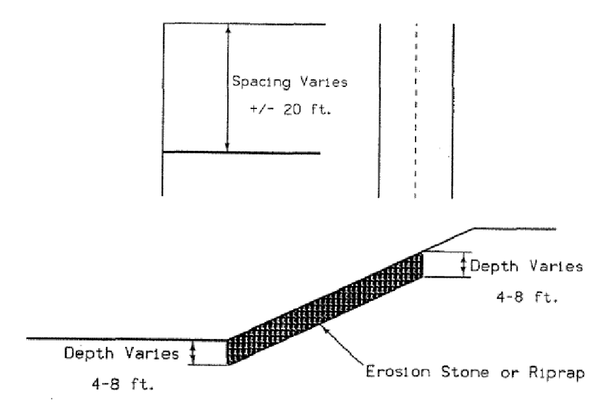
Figure 7: Typical transverse drain (from Lohnes, et. al., 2001).
Buttressing
Rock buttresses can also be used to stabilize foreslopes by increasing the toe resistance, similar to a stability berm. A rock buttress is a slope reconstructed using only large stone material such as riprap or erosion stone as fill material, see Figure 8. Nonwoven geotextile is placed between the rock and subgrade to prevent migration of fines.
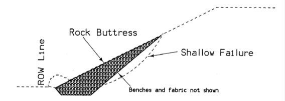
Figure 8: Slope repair with rock buttress (from Lohnes, et.al., 2001).
Granular shear keyways are used to replace low strength material that is influencing the slope stability with higher strength material. These are constructed by excavating a keyway through weaker material into stronger material, and backfilling the keyway with high friction, granular material. The longitudinal granular keyway provides a zone of high shear resistance at the toe of the slope. The extent and location of the shear key dimensions can vary and will be established by the Soils Design Section during the analysis of the slope failure. The location of the granular keyway will influence the amount of excavation required for the repair as shown in Figure 9.
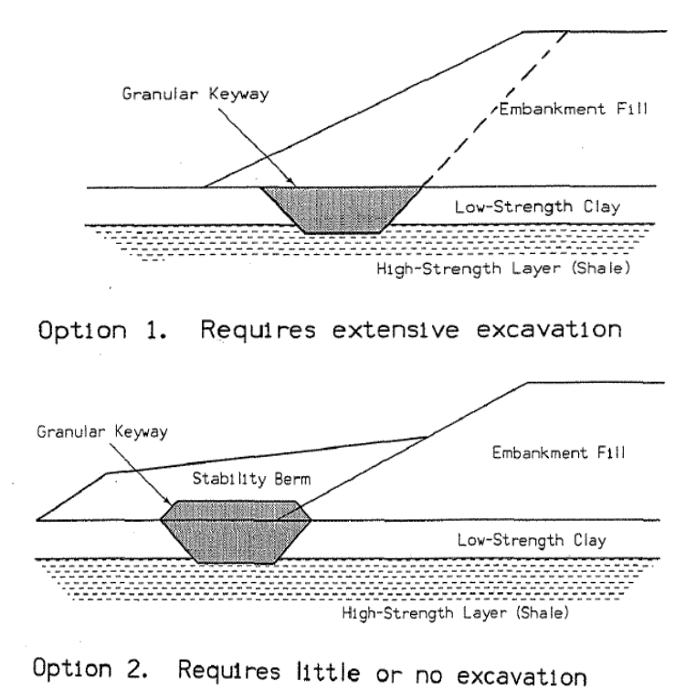
Figure 9: Slope repairs with shear keys (from Lohnes, et. al., 2001).
Erosion Protection
In cases where erosional forces, such as stream or ditch flow, are influencing slope stability, a revetment structure can be constructed to protect the toe of a slope from erosion. The size of the revetment structure and size of revetment material, (i.e., erosion stone to riprap) will depend on the volume and velocity of water flow and impacted area. In most cases, a nonwoven geotextile is placed between the revetment material and exposed subgrade to prevent migration of subgrade material. Most repairs related to erosion around bridge structures are designed by Office of Bridge and Structures with input from the Soils Design Section.
Shoulder Slide Repairs
Erosion stone shoulder fillets consist of reconstructing a relatively shallow portion of the shoulder/foreslope (such as the top 5 to 6 feet) with erosion stone. Engineering fabric is placed between the earth fill and the stone. This fillet helps prevent localized erosion due to surface runoff as illustrated in Soils_1 (Granular Shoulder for Slide Repair), Soils_2 (Combination Shoulder for Slide Repair), Soils_3 (Foreslope Construction for Slide Repair).
Back to topReferences
- Lohnes R.A., Kjartanson B.H., and Barnes A., March 2001. Regional Approach to Landslide Interpretation and Repair, Iowa Department of Transportation and the Iowa Highway Research Board, Iowa DOT Project TR 430.
- Turner, A. K., and Schuster, R. L., editors, 1996, Landslides Investigation and Mitigation, Transportation Research Board, TRB Special Report 247, National Academy Press, Washington, DC.
- USGS, 2013, Landslide Types and Processes, http://pubs.usgs.gov/fs/2004/3072/