
Content Information
On this page...
A. Accessible Shared Use Path Design
- General: Applicable portions from the following draft documents were used to develop this section.
- AASHTO Bicycle Guide: The fourth edition (2012) of the AASHTO “Guide for the Development of Bicycle Facilities” (or AASHTO Bicycle Guide). References made to the AASHTO Bicycle Guide within this section are shown in parentheses, e.g. (AASHTO Bicycle Guide 5.2.1).
- AGODA: The June 20, 2007 Proposed Architectural Barriers Act “Accessibility Guidelines for Outdoor Developed Areas” (AGODA). This document is primarily used for shared use paths designed as bicycle facilities.
- PROWAG: The Public Right-of-Way Accessibility Guidelines (PROWAG) are primarily used for shared use paths designed as sidewalks.
- Documenting Exceptions: If the project cannot fully meet the minimum requirements included within this section, a document should be developed to describe why the minimum requirements cannot be met. It is recommended that this document be retained in the project file. For local agency projects administered through Iowa DOT, a certification with supporting documentation shall be submitted to the Iowa DOT administering bureau. The certification shall be as prescribed by the Iowa DOT and signed by a registered professional engineer or landscape architect licensed in the State of Iowa. For Iowa DOT projects, contact the Design Bureau, Methods Section.
B. Shared Use Path Categories
- Type 1: A shared use path adjacent or in close proximity to the roadway and functions similar to a sidewalk and separated bicycle lane. Due to the proximity to the roadway, intersection crossings of type 1 shared use path should closely follow the best practices of separated bicycle lanes. In rural cross-sections, these paths would be at the top of the foreslope.
- Type 2: A shared use path similar to Type 3, except they serve as a transportation route to facilities that fulfill a basic life need, provide access to a program or service, or provide a safe route for non-drivers.
- Type 3: A shared use path in independent right-of-way or not in close proximity to the roadway. Although Type 3 paths may fulfill a transportation function, these paths primarily serve a recreation and fitness benefit.
One shared use path project may have different combinations of Type 1, Type 2, and/or Type 3 segments, based on location and function. If Federal or State funding is being used on a project, the funding application should identify where Type 1, Type 2, or Type 3 segments will be used.
Back to topC. Shared Use Path Design Elements
The following considerations should be used as a guide when designing shared use paths.
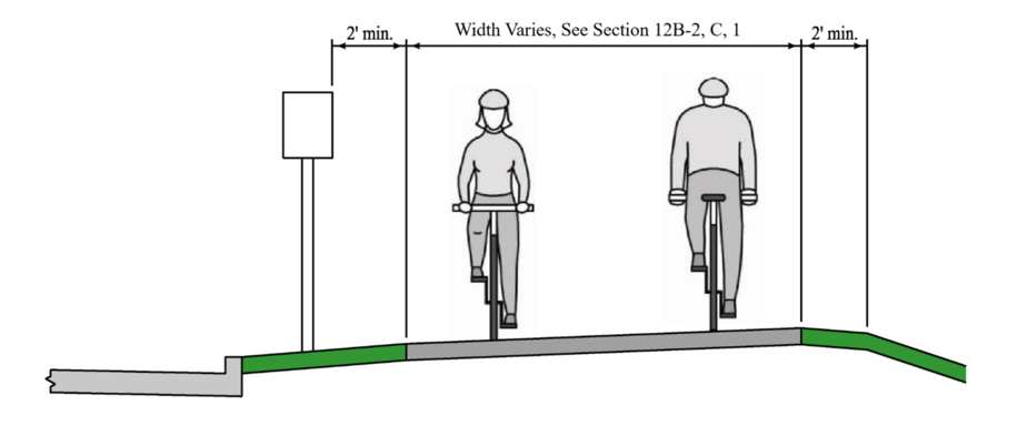
Width: A bicyclist requires a minimum of 4 feet and a preferred 5 feet of essential operating space based upon their profile. The typical path width is 10 to 12 feet to accommodate two-way traffic. The minimum width needed for a bicyclist to pass another path user while maintaining sufficient space for another user approaching from the opposite direction is 11 feet. Consider wider paths (12 to 15 feet) when at minimum one of the following is anticipated:
- User volume exceeding 300 users within the peak hour.
- Curves where more operating space should be provided.
- Large maintenance vehicles.
Path width can be reduced to 8 feet where the following conditions prevail:
- Bicycle traffic is expected to be low.
- Pedestrian use is generally not expected.
- Horizontal and vertical alignments provide well-designed passing and resting opportunities.
- The path will not be regularly subjected to maintenance vehicle loading conditions.
- A physical constraint exists for a short duration such as a utility structure, fence, etc.
- Protection of environmental features.
Path widths between 8 and 5 feet should be avoided; paths less than 5 feet do not meet ADA requirements. If the path width is less than 8 feet, a design exception must be developed.
For Iowa DOT projects involving paths on structures, contact the Bridges and Structures Bureau to determine the structural impacts of shared use path widths.
If segregation of pedestrians and bicycle traffic is desirable, a minimum 15 foot width should be provided. This includes 10 feet for two-way bicycle traffic and 5 feet for two-way pedestrian traffic. (AASHTO Bicycle Guide 5.2.1).
Figure 12B-2.01: Typical Cross-Section of Two-Way Shared Use Path on Independent Right-of-Way
- Minimum Surface Thickness: For Iowa DOT projects, contact the Pavement Design Section in the Design Bureau for a pavement determination. For local agency projects administered through Iowa DOT, Iowa DOT will accept the thickness design as determined by the engineer.
For local projects, the pavement depth for both PCC and HMA pavements should have a minimum of 4 inches and a recommended thickness of 5 inches. If pavement thickness is proposed to be less than 4 inches, a pavement determination should be completed and documented. - Cross Slope: Shared use paths must have the capabilities to serve people with disabilities.
- Type 1 and Type 2: Cross slopes shall not exceed the requirements in Section 12A-2.
- Type 3: A 1.5% cross slope is recommended, but cross slopes should be a minimum of 1% and shall not exceed 5%. Cross slopes greater than 2% should be sloped to the inside of the horizontal curve regardless of drainage conditions. On unpaved paths, cross slopes may increase up to 5% due to the need of draining water off the path. On rare bicycle only facilities, the path does not need to meet accessibility guidelines and the cross slope can be between 5% and 8%. Cross slope transition should be comfortable for the user; therefore, a minimum transition length of 5 feet for each 1% change in cross slope should be used.
Separation of Roadway and Path: A separation of 6 feet or greater between the curb or edge of roadway and the path is desirable to increase pedestrian and bicyclist comfort. Where the distance between the edge of roadway and the edge of the path is less than 5 feet, a vertical element of separation should be provided between the edge of roadway and type 1 or type 2 shared use path for the safety and comfort of path users. This is particularly important at night. For streets with curbs to provide the vertical element, a minimum 2 foot buffer should be provided between the path and the adjacent roadway. On high-speed roadways or uncurbed roadways where the separation from the edge of the traveled way to the near edge of the path 5 feet or less, a crashworthy barrier or railing is needed due to high speeds and clear zone requirements.
At uncontrolled approaches of intersections and at signalized intersections where turning vehicles and bicycle through movements are expected, designers should offset the bicycle crossing between 6 and 16.5 feet from the adjacent motor vehicle lane. This treatment creates a yielding space for motorists and has been shown to reduce crashes at uncontrolled and permissive conflict locations.
- Lateral and Vertical Clearance: The provision of adequate clearance to a wide variety of potential obstructions that may be found along a prospective route is important for creating a safe and comfortable shared use path facility. Guidelines for lateral and vertical clearance are particularly important in view of the wide range of riding proficiency that is found among riders. See Section 12B-3, B for clearance values for obstructions adjacent to bikeways (including shared use paths).
- Lateral Clearances to Fixed and Movable Obstructions: When minimum clearance in Section 12B-3 cannot be achieved, refer to Section 12A-3 for protruding object requirements; refer to the AASHTO Bicycle Guide for mitigation measures, such as pavement markings, delineation, and signing.
Vertical Clearances to Overhead Obstructions: The minimum vertical clearance is 10 feet. In some situations, such as tunnels and bridge underpasses, the vertical clearance should be greater than 10 feet in order to accommodate maintenance and emergency vehicles. In constrained areas, AASHTO allows the vertical clearance to obstructions to be a minimum of 8 feet. (AASHTO Bicycle Guide 5.2.1).
Refer to Section 12A-3 for legal requirements in low clearance situations.
- Shoulder Width and Slope: The minimum graded shoulder width is 2 feet. The maximum shoulder area cross slope is 6:1.
- Safety Rail: Safety rail should be a minimum of 42 inches in height. Provide safety rails at the outside of a structure. On steep fill embankment as described below, provide a safety rail or widen the shoulder area to 5 feet. (AASHTO Bicycle Guide 5.2.1)
- Slopes 3:1 or steeper with a drop of 6 feet or greater.
- Slopes 3:1 or steeper adjacent to a parallel body of water or other substantial obstacle.
- Slopes 2:1 or steeper with a drop of 4 feet or greater.
Slopes 1:1 or steeper with a drop of 1 foot or greater.
Figure 12B-2.02: Safety Rail between Path and Adjacent Slope

See Iowa DOT Design Manual Section 12B-10 for guidance on safety rails.
Source: Adapted from AASHTO Bicycle Guide Exhibit 5.3
- Design Speed and Alignments:
- Type 1: Grades shall meet the requirements of Section 12A-2.
- Type 2: Grades shall be less than or equal to 5% and all other Type 3 requirements should be met.
- Type 3: For most shared use paths with higher volumes of users in relatively flat areas, a design speed of 15 mph is generally sufficient due to the mixed-use operation with pedestrians on the facility. Table 12B-2.01 describes cases in which the design speed should be adjusted based on context. (AASHTO Bicycle Guide 5.2.4)
Table 12B-2.01: Shared Use Path Design Speed by Context
Source: ODOT Multimodal Design Guide
The minimum radius of curvature negotiable by a bicycle can be calculated using the lean angle of the bicyclist or the superelevation and coefficient of friction of the shared use path. A bicyclist must lean two wheeled bicycles while cornering to prevent falling outward due to forces associated with turning movements. A lean angle of 20 degrees is considered the typical maximum lean angle for users to continue pedaling through a turn. Lean angles greater than this typically require bicyclists to stop pedaling to avoid pedal strikes on the pavement. The minimum radii of curvature for a paved path are shown in Table 12B-2.02 based on the typical lean angle of the bicyclists.
Table 12B-2.02: Minimum Radii for Horizontal Curves at Lean Angle
Source: AASHTO Bicycle Guide Exhibit 5.6
The minimum radii of curvature for a paved path based on superelevation should be calculated per the equations shown in the AASHTO Bicycle Guide. (AASHTO Bicycle Guide 5.2.2, 5.2.5, 5.2.6, and 5.2.8).
Table 12B-2.03 and Figure 12B-2.03 should be used to determine the minimum clearance necessary to avoid line-of-sight obstructions for horizontal curves. The lateral clearance (horizontal sight line offset or HSO) can be obtained from Table 12B-2.03, given the stopping sight distance from Equation 12B-2.01 and the proposed horizontal radius of curvature. Lateral clearances on horizontal curves should be calculated based on the sum of the stopping sight distances for both users traveling in opposite directions around the curve because bicyclists have a tendency to ride near the middle of narrow paths.
Table 12B-2.03: Minimum Lateral Clearance (Horizontal Sightline Offset or HSO) for Horizontal Curve
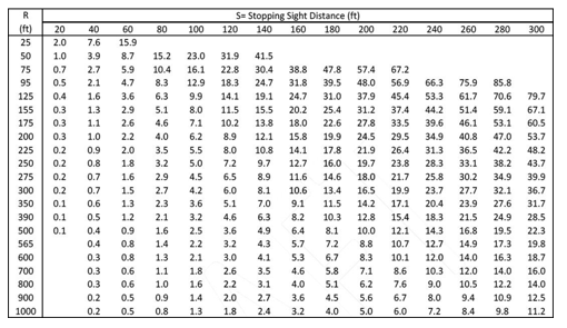
Source: AASHTO Bicycle Guide Exhibit 5.10
Figure 12B-2.03: Components for Determining Horizontal Sight Distance
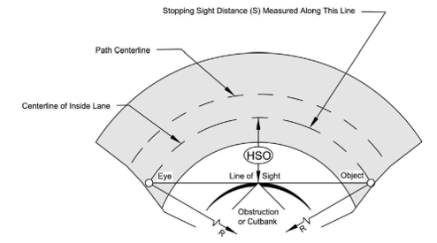
Source: AASHTO Bicycle Guide Exhibit 5.9
For vertical alignment, use the preferred maximum segment length shown in Table 12B-2.04 whenever possible. Using the acceptable and allowed criteria should only be done when the engineer considers the ability of the users. For example, long rural segments would generally serve more physically capable users who have selected the path and could navigate the steeper grades over longer lengths.
Table 12B-2.04: Vertical Alignment
\(^{1}\)Derived from AGODA Section 1016 (Outdoor Recreation Access Routes)
\(^{2}\)Derived from AGODA Section 1017 (Trails)
The minimum length of vertical curve needed to provide minimum stopping sight distance at various speeds on crest vertical curves is presented in Table 12B-2.05. The eye height of the typical adult bicyclist is assumed to be 4.5 feet. For stopping sight distance calculations, the object height is assumed to be 0 inches. (AASHTO Bicycle Guide 5.2.7). Equation 12B-2.01 can also be used to determine the minimum length of crest vertical curve necessary to provide adequate sight distance.
\(S > L,\qquad L = 2S - \frac{200\left(\sqrt{h_1} + \sqrt{h_2}\right)^2}{A}\)
\(S > L \qquad L = 2S - \frac{200\left(\sqrt{h_1} + \sqrt{h_2}\right)^2}{A}\)
\(L > S \qquad L = \frac{A S^2}{100(\sqrt{2h_1} + \sqrt{2h_2})^2}\)
where:
L=Minimum length of vertical curves (ft)
A=Algebraic grade difference (percent)
S=Stopping sight distance (ft)
\(h_1\)=Eye height (4.5 ft for a typical bicyclist)
\(h_2\)=Object height (0 ft)
Table 12B-2.05: Minimum Length of Crest Vertical Curve Based on Stopping Sight Distance
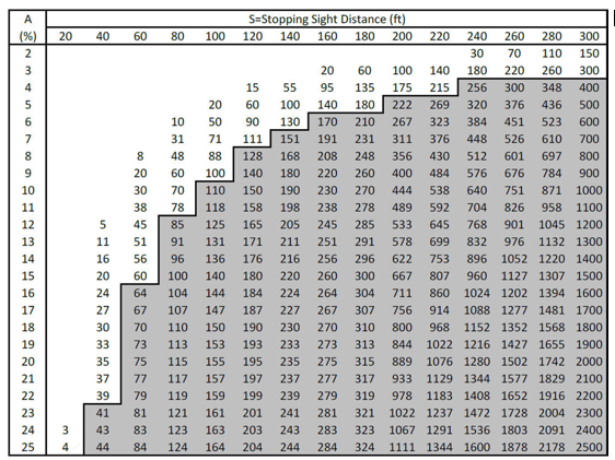
The line between the shaded and un-shaded portions of the table shows when the stopping sight distance is equal to the length of the crest vertical curve.
Source: AASHTO Bicycle Guide Exhibit 5.8
- Stopping Sight Distance: Shared use paths must be designed with adequate stopping sight distance along the entire path to provide users with the opportunity to see and react to unexpected conditions. The distance needed to bring a path user to a fully controlled stop is a function of the user’s perception and braking reaction time, the initial speed, the coefficient of friction between the wheels and the pavement, the braking ability of the user’s equipment, and the grade. Minimum stopping sight distances can be determined using Equation 12B-2.02. Stopping sight distance must be provided along the entire length of the pathway and should be checked at all horizontal and vertical curves. (AASHTO Bicycle Guide 5.2.8).
Equation 12B-2.02
\(S = \frac{V^{2}}{30(f \pm G)} + 3.67V\)
where:
S = Stopping sight distance (ft)
V = Velocity (mph)
f = Coefficient of friction (use 0.16 for a typical bicycle)
G = Grade (ft/ft) (rise/run)
- Accessibility Requirements: For construction of curb ramps and placement of detectable warnings, see Section 12A-2 to ensure ADA compliance.
D. Intersection Sight Distance
General: Intersection sight distance is a fundamental component in the selection of appropriate control at a midblock path-roadway intersection. The least restrictive control that is effective should be used. The line of sight is considered to be 2.3 feet above the path surface.
Roadway approach sight distance and departure sight triangles should be calculated using motor vehicles, which will control the design criteria. (AASHTO Bicycle Guide 5.3).
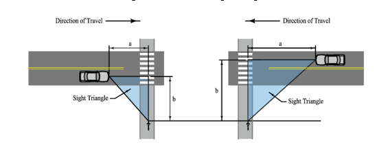
Approach Sight Distance: Pathway approach sight distance should be determined by the fastest path user, typically the adult bicyclist. If yield control is to be used for either the roadway approach or the path approach, available sight distance adequate for a traveler on the yield controlled approach to slow, stop, and avoid a traveler on the other approach is required. The roadway leg (a) of the sight triangle is based on the ability of a bicyclist to reach and cross the roadway if they do not see a conflict (see Figure 12B-2.04). Similarly, the path leg (b) of the sight triangle is based on the ability of a motorist to reach and cross the junction if they do not see a conflict (see Figure 12B-2.04). If sufficient sight distance is unable to be provided by the yield sight triangle described above, more restrictive control should be implemented.
For Type 1 shared use paths crossing a roadway near an intersection, refer to Section 12B-3, F, 3 for additional geometric design treatments.
Figure 12B-2.04: Yield Sight Triangles
Source: Adapted from AASHTO Bicycle Guide Exhibit 5.15
\(a = 1.47\,V_{Road}\left( \frac{S}{1.47\,V_{Path}} + \frac{w + L_a}{1.47\,V_{Path}} \right)\) Equation 12B-2.03 Length of Roadway Leg of Sight Triangle
\(b = V_{path}\left( \frac{1.47V_e - 1.47V_b}{a_i} + \frac{w + L_a}{0.88V_{road}} \right)\) Equation 12B-2.04 Length of Path Leg of Sight Triangle
Where,
a=Length of leg of sight triangle along the roadway approach (ft)
b=Length of leg of sight triangle along the path approach (ft)
w=Width of the intersection to be crossed (ft)
\(V_{a}\)=Design vehicle length
For Equation 12B-2.03 :Typical bicycle length =6ft
For Equation 12B-2.04 :Design vehicle length (ft)
\(V_{path}\)= Design speed of the path (mph)
\(V_{road}\)= Design speed of the road (mph)
S = Stopping sight distance for the path user traveling at design speed
\(V_e\)= Speed at which the motorist would enter the intersection after decelerating (mph)
(assumed 0.60 x road design speed )
\(V_b\)= Speed at which braking by the motorist begins(mph) (same as road design speed)
\(a_i\)= motorist deceleration rate (ft/s2) on intersection approach when braking to a stop is not initiated (assume -5.0 ft/s2 )
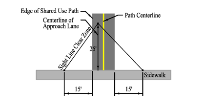
Path-Sidewalk Intersection: At an intersection of a shared use path and a sidewalk, a clear sight triangle extending at minimum 15 feet along the sidewalk must be provided. Refer to Figure 12B-2.05. If two shared use paths intersect, the same process for the roadway-path intersection should be used.
Figure 12B-2.05: Minimum Path-Sidewalk Sight Triangle
Source: Adapted from AASHTO Bicycle Guide Exhibit 5.16
E. Surface
It is important to construct and maintain a smooth riding surface on shared use paths. Shared use path pavements should be machine placed. Surface texture is needed but care must be exercised not to cause operational problems with too little or too much texture. Broom finish or burlap drag concrete surfaces are preferred over trowel finishes. Joints shall be sawed, not hand tooled.
- Type 1 and Type 2: Type 1 and Type 2 shared use paths shall be paved.
- Type 3: Hard, all-weather pavement surfaces are preferred to unpaved surfaces due to the higher service quality and lower maintenance. Type 3 shared use paths should be paved; however, a granular surface may be allowed. If a granular surface is used, it must be maintained to be firm, stable, and slip resistant.
F. Crossings at Unpaved Surfaces
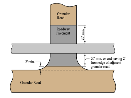
When crossing an unpaved roadway, alley, or driveway, a minimum of 20 feet in addition to the path width should be paved on each side of the path to reduce the amount of gravel tracked onto the path. If edge of parallel unpaved roadway is less than 20 feet from the closest edge of the path, only pave to within 2 foot of edge of the parallel unpaved roadway. The thickness of the path and adjacent roadway paving should be designed to accommodate vehicular traffic and meet the requirements of the agency responsible for the roadway.
Figure 12B-2.06: Crossing at Unpaved Surface
G. At-grade Railroad Crossing
Whenever it is necessary to cross railroad tracks with a bicycle, special care must be taken. The crossing should be at least as wide as the approaches of the shared use path. Whenever possible, the crossing should be straight and between 90 and 60 degrees to the rails. The greater the crossing angle deviates from being perpendicular, the greater the chance that a bicyclist's front wheel may be trapped in the flangeway causing a loss of control. (AASHTO Bicycle Guide 4.12).
Back to topH. Drainage
Drainage structures underneath paths should typically be designed to the same design year storm as the roadway drainage structures. When a Type 3 shared use path is built on a berm, consider the drainage needs of that path. For shared use paths constructed on slopes, drainage design should take into account control of the runoff from the slope. For higher flows it may be necessary to develop parallel ditches and culverts under the path. Drainage designs should also provide for low flows and seepage from the slope. Due to the potential for accidents from buildup of algae from low flows and side hill seepage, the need for subdrains or other treatments on the high side of the path should be evaluated.
- Urban Areas: The minimum recommended pavement cross slope of 1% usually provides enough slope for proper drainage. Sloping in one direction, usually toward the street, instead of crowning is preferred and usually simplifies the drainage and surface construction. However, care must be exercised not to trap water on the high side of the shared use path, particularly in curved areas. (AASHTO Bicycle Guide 5.2.11).
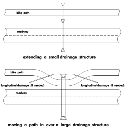
- Rural Areas: The best way to accomplish drainage underneath a shared use path is by extending smaller structures under the path or moving the path closer to the roadway to cross larger structures, see Figure 12B-2.07.
For paths placed on the backslope, smaller drainage structures (normally pipes less than 60 inches and box culverts less than 5 feet by 4 feet) should be extended through the path. For larger culverts, the path should be moved in to cross the structure and then moved back out to the backslope. If this is done, longitudinal drainage will have to be provided where the path crosses the ditch. Depending upon how close the path comes to culvert openings, safety railing may be needed on the culverts.
For paths on the foreslope, culverts should be extended as necessary.
Figure 12B-2.07: Accommodating Drainage Structures
I. Structure Design
The preferred bridge width for shared use path is equal to the width of the path plus 4 feet, which provides 2 feet of clearance on each side, according to the AASHTO Bicycle Guide. It is acceptable to provide bridge widths equal to the width of the path plus 2 feet, which provides 1 foot of clearance on each side. In constrained situations, the bridge width may equal the path width so long as the landings are adequately tapered from the clear zone to the bridge. For a 10 foot wide path, the resulting specified bridge widths are:
- 14 feet (preferred)
- 12 feet (acceptable)
- 10 feet (in constrained conditions)
For Iowa DOT administered projects, the designer should contact the Design Bureau and the Traffic and Safety Bureau for further assistance if considering a narrowed path across a bridge.
Back to topJ. Pavement Markings
Ladder or zebra pavement markings per MUTCD are recommended at crosswalks. Other pavement markings are not required, except as mitigation strategies. (AASHTO Bicycle Guide 5.4).
Back to topK. Signing
All signs should be retroreflective and conform to the color, legend, and shape requirements described in the MUTCD. In addition, guide signing, such as to indicate directions, destinations, distances, route numbers, and names of crossing streets should be used. In general, uniform application of traffic control devices, as described in the MUTCD, should be used and will tend to encourage proper bicyclist behavior. (AASHTO Bicycle Guide 5.4).
Back to topL. Lighting
Fixed-source lighting reduces conflicts along shared use paths and at intersections. In addition, lighting allows the bicyclist to see the shared use path direction, surface conditions, and obstacles. Lighting for paths is important and may be considered where heavy nighttime riding is expected (e.g., paths serving college students or commuters) and at roadway intersections. Lighting should be considered through underpasses or tunnels and when nighttime security could be a problem. Where special security problems exist, higher illumination levels may be considered. Light standards (poles) should meet the recommended horizontal and vertical clearances. (AASHTO Bicycle Guide 5.2.12).
Back to top