
Content Information
On this page...
- A. General
- B. Elements of Design
- C. Shared Lanes
- D. Paved Shoulders
- E. Bicycle Lanes
- F. Intersection Design
- G. Retrofitting Bicycle Facilities on Existing Roadways
- H. Bicycle Boulevards
- I. Bicycle Guide Signs
- J. Railroad Crossings for Bicycles
- K. Obstruction Markings for Bicycle Lanes
- L. Traffic Signals for Bicycles
- M. Bridges and Viaducts for Bicycles
- N. Traffic Calming and Management of Bicycles
- O. Intake Grates and Manhole Castings for Bicycle Travel
- P. Bicycles at Interchanges
- Q.Bicycles at Roundabouts
- R. References
- Chronology of Changes
A. General
Except where prohibited, bicycles may operate on all roadways. This section describes the different types of bicycle facilities located on the roadway, along with their design criteria.
Bicyclists have similar access and mobility needs as other transportation users. However, bicyclists must use their own strength and energy to propel the bicycle or use e-bike. Even then, a bicyclist is generally slower than other vehicles operating on the roadway. Additionally, bicyclists are more vulnerable to injury during a crash and are of any age group. With these factors in mind, it is imperative to design bicycle facilities with great care.
The fourth edition (2012) of the AASHTO “Guide for the Development of Bicycle Facilities” (or AASHTO Bicycle Guide) was used as a reference for developing this section. References made to the AASHTO Bicycle Guide within this section are shown in parentheses, e.g. (AASHTO Bicycle Guide 4.2).
Back to topB. Elements of Design
Since bicyclists usually have a higher eye height and are slower than the adjacent traffic, the roadway design elements for motor vehicles usually meet or exceed the minimum design elements required for bicyclists. Additional considerations and exceptions are described below.
Bicyclist Design Speed: Where bicyclists are operating on roadways (bicycle lanes, shared lanes, bicycle boulevards, and paved shoulders), designing streets meeting basic geometric design guidelines for motor vehicles will result in a facility generally accommodating bicyclists in terms of grades, stopping sight distance, horizontal and vertical alignment, and cross slopes.
Where separated bicycle lanes are present and geometric elements such as shifting tapers are introduced specifically for bicyclists, a design speed for the typical bikeway user is appropriate. Using the typical adult bicyclist to establish design speeds ensures the geometric design accommodates slower users, including children, seniors and less confident adult bicyclists, pedestrians, and others. The typical adult bicyclist travels at speeds of less than 15 mph on flat level terrain, with average speeds closer to 10 mph. Consideration should also be given to higher speed e-bikes, which are allowed to reach speeds of 28 mph.
Speeds slower than the design speed should be considered for some elements of design, such as using 8 mph for signal timing to account for slower bicyclists (e.g., children and seniors) who need more time to cross intersections.
- Stopping Sight Distance: Bicycle stopping sight distance is the distance needed to bring a bicycle to a fully controlled stop. It is a function of the user’s perception and brake reaction time, the initial speed, the coefficient of friction between the wheels and the pavement, the braking ability of the user’s equipment, and the grade. See AASHTO Bicycle Guide 5.2.8 for calculating stopping sight distance.
Intersection Sight Distance: Roadway approach sight distance and departure sight triangles should be calculated according to procedures in AASHTO’s A Policy on Geometric Design of Highways and Streets because motor vehicles will control the design criteria.
Where a stop controlled roadway intersects an uncontrolled roadway, bicyclists must judge the speed of, and gaps in, approaching motor vehicle traffic from their location at the edge of the roadway (see Figure 12B-3.01). Providing the minimum stopping sight distance for the motorist on the uncontrolled roadway approach will allow the motorist sufficient time to exercise due care to slow or stop for the crossing bicyclist who may still be in the intersection. Table 12B-3.01 provides the length of the departure sight triangle along the roadway to allow the bicyclist enough time to judge a gap in traffic and complete a full crossing of the roadway without a motorist needing to slow or stop. The table assumes a bicyclist with a:
- design acceleration of 2.5 square feet,
- maximum speed of 8 mph to account for a slow bicyclist, and bicycle length of 6 feet.
bicycle length of 6 feet.
Figure 12B-3.01: Bicyclist Crossing from a Minor Road
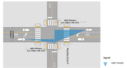
Table 12B-3.01: Bicyclist Sight Distance Crossing from a Minor Road
Based on Standing Bicycle Crossing Time and Motor Vehicle Stopping Sight Distance
Bicyclist Operating Space and Shy Space: As stated in Section 12B-2, C, a bicyclist requires a minimum of 4 feet operating space. To maintain comfort and safety of bicyclists, it is preferable to provide shy spaces (lateral clearances for vertical elements or obstructions adjacent to bikeways) outside the operating space of the bicyclist. However, for bikeways within the roadway, it may not be practicable to provide shy space to parked and moving motor vehicles. Where minimum shy spaces are not provided, the usable width intended for bicycle travel, and the level of comfort for the facility, is likely to be reduced. Table 12B-3.02 provides guidance for determining an appropriate clearance distance to common vertical elements.
In addition to fixed objects, bicyclists have the potential to collide into other bicyclists or pedestrians (on shared use paths) where a bikeway width limits their ability to operate side-by-side, to pass other bicyclists, or to pass pedestrians. Bikeways should be constructed to serve the expected volume of users to minimize this crash risk. Table 12B-3.02 describes the preferred shy space for “bicycle traffic,” which accommodates passing or side-by-side bicycling. Where it is desired to accommodate side-by-side bicycling or frequent passing, shy space should be provided between the operating spaces of each bicyclist. Where it is not desired to encourage bicyclists to ride side-by-side, shy space should still be provided between the physical spaces of each bicyclist to accommodate the occasional passing of bicyclists.
Table 12B-3.02: Bicyclist Shy Space
* Vertical curb without gutter 3 inches or greater. Where a gutter is provided, the shy space is equal to the width of the gutter.
Source: Adapted from Minnesota Bicycle Facility Design Manual
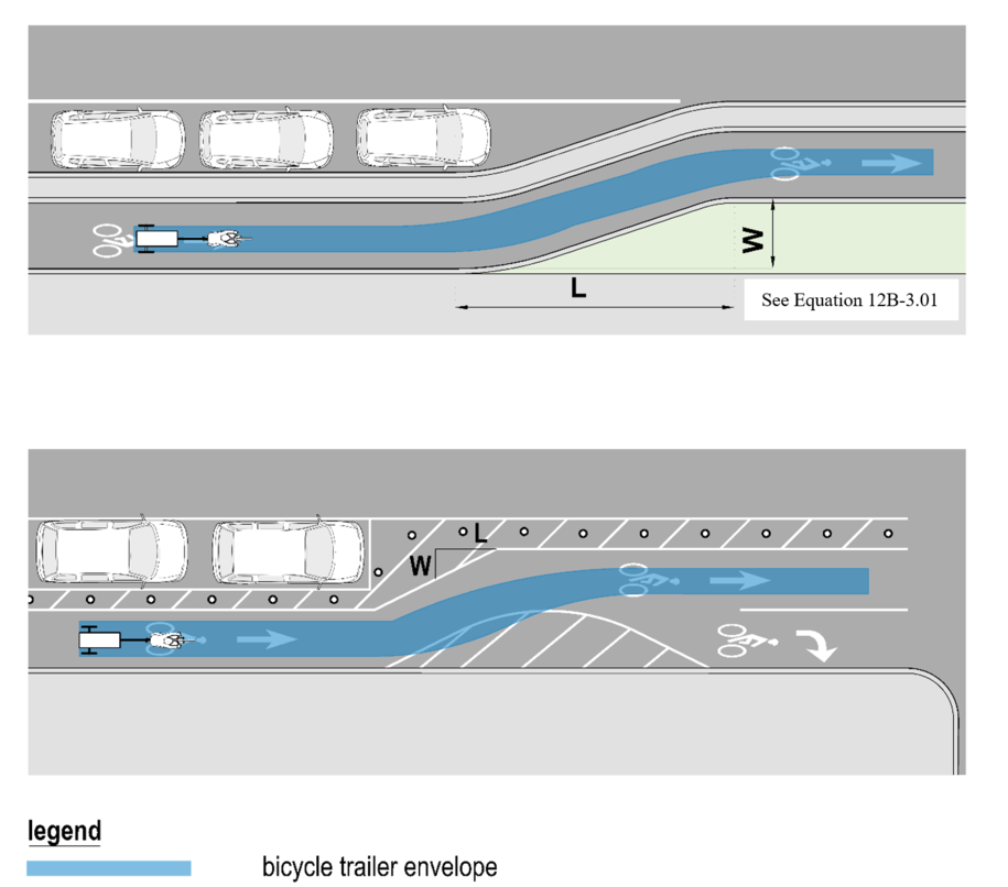
Bicycle Tapers: Tapers may occur where designers wish to slow bicyclists in advance of an intersection or where a bicycle lane must be shifted to introduce a turn lane. Tapers should generally occur gradually, with a minimum length as calculated using Equation 12B-3.01. If the bikeway is delineated by paint only, and if the off tracking of a bicycle pulling a trailer would not put the trailer into a motor vehicle lane, a maximum taper ratio of 2:1 (longitudinal: lateral) may be considered, see Figure 12B-3.02.
Equation 12B-3.01
\(L = \frac{W S^2}{60}\)
Where,
L= Lane shift, ft (minimum 20 feet)
W=Width of offset, ft
S=Target bicyclist operating speeds, mph
Figure 12B-3.02: Shifting Taper Equation
Source: Adapted from MUTCD Figure 3B-14
Pavement Conditions: Surface conditions affect bicyclists more significantly than motor vehicles. Therefore, when establishing bicycle lanes and routes, it is important that the roadway surface is in good condition and is free of potholes, bumps, cracks, loose gravel, etc. If the roadway is not in good bicycle riding condition, it should be repaired either with resurfacing or reconstruction. Chip-sealed surfaces prove to create difficult riding conditions. (AASHTO Bicycle Guide 4.2).
In addition to fixed objects, bicyclists have the potential to collide into other bicyclists or pedestrians (on shared use paths) where a bikeway width limits their ability to operate side-by-side, to pass other bicyclists, or to pass pedestrians. Bikeways should be constructed to serve the expected volume of users to minimize this crash risk. Table 12B-3.02 describes the preferred shy space for “bicycle traffic,” which accommodates passing or side-by-side bicycling. Where it is desired to accommodate side-by-side bicycling or frequent passing, shy space should be provided between the operating spaces of each bicyclist. Where it is not desired to encourage bicyclists to ride side-by-side, shy space should still be provided between the physical spaces of each bicyclist to accommodate the occasional passing of bicyclists.
C. Shared Lanes
Shared lanes already exist on local neighborhoods and city streets. Shared lanes may be identified with signage and markings or be left unmarked. They are not recommended for roadways with speeds over 35 mph or traffic volumes over 5,000 AADT. In addition, shared lanes on roadways with speeds greater than 25 mph or volumes over 3,000 AADT are unlikely to accommodate the “interested but concerned” bicyclist but could accommodate the “highly confident” bicyclists (see Section 12B-1).
The designs and dimensions for shared lanes differ by location, but attention to design features can make the lanes more comfortable for all bicyclists. This includes good pavement quality, adequate sight distance, lower motor vehicle speeds, appropriate signal timing and detection systems, bicycle-compatible drainage grates, bridge expansion joints, railroad crossings, etc. (AASHTO Bicycle Guide 4.3).
Where bicyclists are operating in shared lanes, travel lane widths should generally be the minimum widths appropriate for the context of the roadway. In the past, it was common practice to provide wider outside lanes (14 feet or greater) under the assumptions motorists in such a lane could pass a person riding a bicycle without encroaching into the adjacent lane and this practice would improve operating conditions and safety for both bicyclists and motorists. However, research finds this configuration does not adequately provide safe passing distance and motorists generally do not recognize this additional space is intended for bicyclists. Wider travel lanes are also associated with increases in motor vehicle speeds, which reduce comfort and safety for bicyclists. Wide lanes are therefore not recommended as a strategy to accommodate bicycling. Where wide lanes exist, roadways should at a minimum be restriped to reduce wide lanes to minimum lane widths. Additional space may be reallocated to other purpose such as bicycle lanes, wider sidewalks, etc.
The use of constrained width bicycle lanes (see Section 12B-3, C, 3) is preferable to a wide outside lane. However, the use of minimum constrained width bicycle lanes should be limited to constrained roadways where preferred minimum bicycle lane widths cannot be achieved after all other travel lanes have been narrowed to minimum widths appropriate for the context of the roadway.
Shared Lane Markings: In areas that need to provide enhanced guidance for cyclists, shared lanes may be marked with pavement marking symbols. This marking should be provided in locations where there are insufficient widths to provide bicycle lanes or shared use paths. This pavement marking not only lets the cyclists know where to be located within the lane but also the direction of travel.
Shared lane markings are not appropriate for paved shoulders or bicycle lanes, and should not be used on roadways that have a speed limit above 35 mph. Markings should be placed immediately after an intersection and spaced not greater than 250 foot intervals. Refer to both the MUTCD and AASHTO Bicycle Guide 4.4.
Shared Lane Signs: Along with pavement markings, signage is very useful to reinforce to motorists the legal right of bicyclists about shared operating along a roadway.
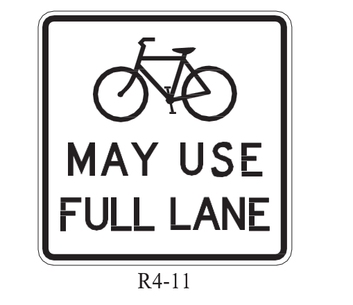
The recommended sign for use in shared lane conditions is the “BICYCLES MAY USE FULL LANE” sign (R4-11). This sign is used on roadways without bicycle lanes or usable shoulders where travel lanes are too narrow for bicyclists and motorists to operate side by side within a lane (typically less than 14.5 feet). Use of the “SHARE THE ROAD” sign (W16-1P) is not recommended due to the ambiguous message it sends. Refer to both the MUTCD and AASHTO Bicycle Guide 4.3.2.
Figure 12B-3.03: Shared Roadways
D. Paved Shoulders
“Highly confident” or “somewhat confident” bicyclists are most likely to travel long distances on rural roadways between towns and cities and are often assumed as the default design user profiles. Paved shoulders can improve these bicyclists’ safety and comfort along higher speed and higher volume roadways. This will not only benefit the cyclists and motorists by giving the bicyclists a place to ride that is located outside of the travel lane, but it also can extend the service life of roads by reducing edge deterioration.
Paved shoulders should meet the standards set forth in Iowa DOT’s Bicycle and Pedestrian Long Range Plan and shown in Table 12B-3.04, which vary depending on Average Daily Traffic of the roadway. Also, they should include shy space for guardrails or vertical obstructions, as set forth in Table 12B-3.02. Additionally, the width may be increased in areas of heavy truck traffic.
Table 12B-3.04: Paved Shoulder Standards
*On roadways where a higher level of bicycle traffic is expected (e.g. bicycle routes identifies by municipalities or other agencies.
**Paved width exclusive of rumble strips
Source: Iowa DOT Bicycle and Pedestrian Long Range Plan
It is preferred to have paved shoulders on both sides of a two-way roadway; however, in constrained locations and where pavement widths are limited, it may be preferable to provide a wider shoulder on one side of the roadway and a narrower shoulder on the other. This is beneficial in uphill roadway sections to provide slow-moving bicyclists additional maneuvering space and sections with vertical or horizontal curves that limit sight distance over crests and on the inside of horizontal curves.
Paved shoulders can be designated as bicycle lanes by installing bicycle lane symbol markings and must follow the criteria in Section 12B-3, E. Along rural roads with higher speeds (45 mph or greater) it is preferable to provide a shared use path separated from the road if the road segment:
- is a well used and important bicycle route,
- is located in an area that attracts larger volumes of bicycling due to scenic views, and
- serves as a key bicycle connection between major destinations.
In locations where unpaved driveways or roadways meet a paved shoulder, it is recommended to pave at least 10 feet of the driveway and 20 feet or to the right-of-way line, whichever is less, of the unpaved public road. This will help minimize loose gravel from spilling onto the travel way and affecting the bicyclists. Additionally, raised pavement markers should not be used, unless they are beveled or have tapered edges.
Rumble strips may be used on paved shoulders that include the bicycle traffic. A bicyclist requires a minimum of 4 feet and a preferred 5 feet of essential operating space based upon their profile. When rumble strips are used, a minimum clear path 4 feet from the rumble strip to the outside edge of paved shoulder or 5 feet to the adjacent curb or other obstacle should be provided, with wider clear paths preferred. Gaps of 12 to 15 feet and a recommended distance of 40 to 60 feet for the rumble strips should also be provided in order to allow room for bicyclists to leave or enter the shoulder without crossing the rumble strip. A 15 foot gap allows approximately half a second for a bicyclist to cross the rumble strip at an operating speed of 20 mph or less. Designers should consider increasing the gap length to a range of 15 to 20 feet or shifting the rumble strip to the right side of the shoulder in locations where bicyclists are traveling at speeds over 20 mph and likely need to traverse the rumble strip into the travel lane. Rumble strips should have the following design and meet NCHRP Report 641:
- Width: 7 inches
- Depth: 0.375 inches
- Spacing: 11 to 12 inches (may be reduced to 6 inches)
- Length: 6 to 12 inches
E. Bicycle Lanes
Bicycle lanes are a portion of the roadway that is designated for bicycle traffic. The following sections discuss several types of bicycle lanes including buffered bicycle lanes, separated bicycle lanes, and contraflow bicycle lanes. For guidance on how to select one of these bicycle facilities, refer to Section 12B-1. Public information and education programs may be necessary when a specific type of bicycle lane is introduced into a community. Programs should include a focus for drivers, as well as for bicyclists. Paved shoulders can be designated as bicycle lanes by installing bicycle lane symbol markings, yet marked shoulders will still need to meet the criteria listed herein.
Bicycle lanes should have a smooth surface with utility and grate covers flush with the surface of the lane. Additionally, bicycle lanes should be free of ponding water, washouts, debris accumulation, and other potential hazards. (AASHTO Bicycle Guide 4.6). Designers need to be aware that pavement joints, especially near curb and gutter sections, could impact the usability of the bicycle lane.
- Bicycle Lane Widths: The widths prescribed in Table 12B-3.05 accommodate a bicyclist operating space, occasional passing, and shy distances to vertical elements as presented in Table 12B-3.02. The bicycle lane should be a hard and smooth rideable surface, clear of defects, joints, and other potential obstructions. The gutter should not be included in the measurement of the bicycle lane width because it is not a rideable surface and the gutter presents a potential crash hazard. The only exception is locations where the gutter is incorporated into the full width of the bicycle lane. In those instances, the gutter should be designed to provide a smooth rideable surface with no longitudinal joints or seams parallel to the bicyclist’s line of travel.
Table 12B-3.05: One-Way Bicycle Lane Width Criteria
\(^{1}\)Exclusive of the gutter unless the gutter is integrated into the full width of the bicycle lane.
\(^{2}\) Raised bicycle lanes adjacent to parking should have a minimum width of 7 feet.
Source: Adapted from Minnesota Bicyle Facility Design Manual
Where a bicycle lane is adjacent to a curb with no gutter, the bicycle lane width should be measured from the face of curb to the center of bicycle lane line. For streets with on-street parking, the bicycle lane width should be measured from the center of the parking lane or buffer line to the center of the bicycle lane line.
Figure 12B-3.04: Conventional Bicycle Lane Cross-sections - Parking Prohibited
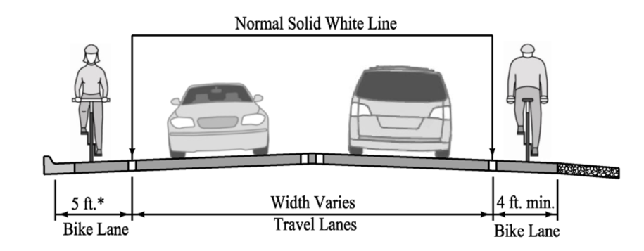
* On extremely constrained, low-speed roadways with curbs but no gutter, where the preferred bicycle lane width cannot be achieved despite narrowing all other travel lanes to their minimum widths, a 4 foot wide bicycle lane can be used.
Source: Adapted from AASHTO Bicycle Guide Exhibit 4.13
The width of a bicycle lane and buffer (if provided) have a significant impact on a bicyclist comfort and their operating position within a bicycle lane. As the adjacent motorized traffic volume and speed increases, bicyclists will try to move away from vehicles operating in the adjacent travel lane, positioning themselves closer to parked vehicles or the edge of roadway, which can increase their crash risk. Bicycle lanes should therefore be built to preferred widths to address the comfort and safety of bicyclists operating within the lane adjacent to the motorized traffic. While bicycle lanes wider than 7 feet may be provided, they should be complemented by a buffer to minimize their appearance as a travel or parking lane for motorists (see Section 12B-3, E, 7).
Example conditions where wider bicycle lanes or buffered bicycle lanes may be preferable include:
- Locations with high parking turnover.
- Locations where it is desirable to allow bicyclists to travel side-by-side or pass each other.
- On roadways with posted speeds over 30 mph or 6,000 vehicles/day.
- On roadways with more than 5% heavy vehicles/trucks.
- Locations where bicycle lanes are located between two moving travel lanes such as between a through lane and turning lane.
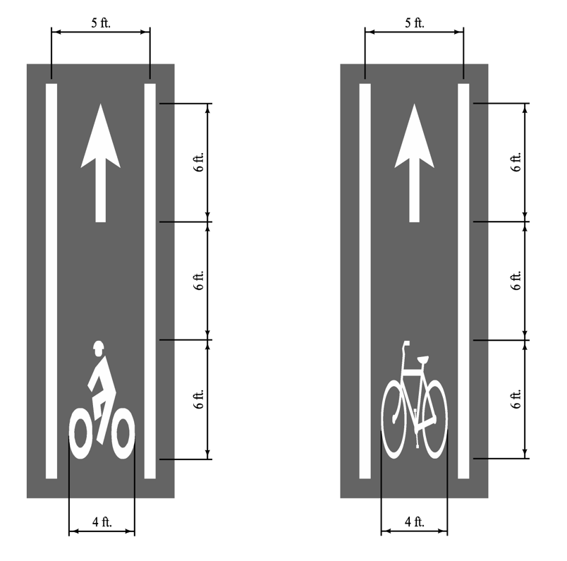
Markings for Bicycle Lanes: Bicycle lanes are designated for preferential use by bicyclists with a white lane line and one of the two standard bicycle lane symbols, which should be supplemented with a directional arrow marking indicating the correct direction of travel in the bicycle lane. The lane line may be a normal width (4 to 6 inches wide) or it may be a wide width (8 to 12 inches wide) to add emphasis, see Figure 12B-3.5. Bicycle lane signs may be used to supplement the pavement markings. All bicycle lane markings should be retroreflective. Refer to both the MUTCD and AASHTO Bicycle Guide 4.7 for bicycle lane markings and Section 12B-3, F for bicycle lane markings at intersections.
Figure 12B-3.05: Conventional Bicycle Lane Symbol Markings
Source: Adapted from AASHTO Bicycle Guide Exhibit 4.17
Bicycle Lanes on One Side of a Two-way Street: It is recommended that bicycle lanes are provided on both sides of two-way streets. Bicycle lanes on only one side may encourage wrong-way use. The following scenarios note when it may be acceptable to provide a bicycle lane on one side and how to select which side:
- On streets where downhill grades are long enough to result in bicycle speeds similar to typical motor vehicle speeds, then a bicycle lane may be provided only in the uphill direction, with shared lane markings in the downhill direction. This design can be especially advantageous on streets where fast downhill bicycle speeds have the potential to increase the likelihood of crashes with fixed objects, particularly in locations with on-street parking.
- Where a roadway narrows on one side of a roadway for a short segment with an otherwise continuous bicycle lane.
- Where an adjacent parallel roadway of similar width provides a bicycle lane in the opposing direction.
When a bicycle lane is only provided in one direction, shared lane markings should be added in the opposing direction if the roadway speed is 35 mph or below.
Bicycle Lanes on One-way Streets: On one-way streets, the bicycle lane should be on the right-hand side of the roadway. A bicycle lane may be placed on the left side of the roadway if there are a significant number of right turn lanes, or if left sided bicycle lanes will reduce conflicts with bus traffic, on-street parking, and/or heavy right-turn movements, etc. Left side bicycle lanes may increase crash risks for bicyclists because it is generally an unexpected location for bicyclists. To mitigate this risk, left side bicycle lanes should be restricted to streets with posted speeds below 30 mph and implemented on a consistent basis in a community. Consideration should be given to increasing the conspicuity of the bicycle lane through the use of wider bicycle lane lines, additional bicycle lane markings, green colored pavement, and additional regulatory or warning signs notifying motorists of the left side placement.
Bicycle lanes should also be provided on both streets of a one-way couplet as to provide a more complete network and discourage wrong-way riding. If width constraints are in effect, shared lane markings should be considered.
Counterflow Bicycle Lanes: Bicycle lanes should typically be provided on both streets of a one-way couplet. If a one-way roadway pair in the opposite direction does not exist or would significantly increase bicyclist travel time due to out of direction travel, there may be an increase in wrong way riding. If sufficient width exists, a counterflow bicycle lane can also be added to provide for two-way bicycle travel on a one-way street. A bicycle lane should be provided for bicyclists traveling in the same direction as motor vehicle traffic. If there is insufficient room to provide a bicycle lane in the dominant flow direction of the street, shared lane markings should be considered to emphasize that bicyclists must share the travel lane on this side of the street.
To mitigate potential safety challenges associated with counterflow bicycle travel, the following should be considered:
- The bicycle lane should be marked according to normal rules of the road so bicyclists using the lane are traveling on the right-hand side of the roadway, with opposing traffic on their left.
- Bicycle lane symbols and directional arrows should be used on both the approach and departure of each intersection, to remind bicyclists to use the bicycle lane in the appropriate direction, and to remind motorists to expect two-way bicycle traffic.
- Because counterflow bicycle travel can be unexpected by motorists when entering, exiting or crossing the roadway, additional treatments including signs and green colored conflict markings (see Section 12B-3, F) should be considered at intersections, alleys, grade crossings, and driveways.
- At intersecting streets, alleys, and major driveways, “DO NOT ENTER” signs and turn restriction signs should include a supplemental “EXCEPT BICYCLES” plaque to establish that the street is two-way for bicyclists.
- At traffic signals, signal heads should be provided for counterflow bicyclists, as well as suitable bicycle detection measures. A supplemental plaque that says “BICYCLE SIGNAL” may be needed beneath the signal to clarify its purpose. See Section 12B-3, L, 1 for information on signal options for controlling bicyclists.
- A solid double yellow center line should be used to separate the counterflow bicycle lane from opposite direction traffic. Medians or traffic separators should be considered to provide more separation between motorists and bicyclists traveling in opposing direction, particularly at intersections. This treatment is required when posted speeds exceed 35 mph.
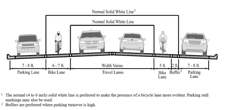
Bicycle Lanes Adjacent to On-street Parking: Where on-street parking facilities are present, bicycle lanes should be located between the general purpose travel lane and the parking lane, unless designated as a separated bicycle lane. Delineating the bicycle lane with two stripes, one along the street side and one along the parking side, is preferable to a single stripe between the bicycle lane and travel lane.
When parallel parking lanes are narrow or there is a high parking turnover, it is preferable to provide a separated bicycle lane to reduce conflicts with the vehicles. When a separated bicycle lane is not feasible or an interim solution is needed, a buffered bicycle lane should be provided, see Section 12B-3, E, 7. It is preferable that the combined width of the parking lane and buffer be at least 10.5 feet wide to allow the opening of motor vehicle doors.
If a striped buffer is not desired, the bicycle lane width may be increased to provide bicyclists with more operating space to ride out of the area of opening vehicle doors; however, as bicycle lane widths increase, they may appear more like travel lanes and may result in instances of double parking. Designers may consider the use of green pavement to discourage motorists using the bikeway. If a buffered bicycle lane is not feasible, designers should consider the following options in the order stated:
- Evaluate the reduction of travel lane widths and parking lane widths to accommodate the design widths for buffered bicycle lanes. For parallel on-street parking, the recommended width of a marked parking lane is 8 feet to encourage vehicles to stay within the parking lane. A parking lane of 9 feet may be preferable in areas where trucks are routinely present.
- Evaluate if parking can be consolidated to one side of the street or removed to provide the additional space necessary to accommodate the design widths for buffered bicycle lanes.
- On constrained streets where it is not feasible to eliminate parking, or to narrow or remove a travel lane, in order to achieve the minimum dimensions, research indicates there is a slightly reduced risk of dooring in bicycle lanes as compared to shared lanes. The bicycle lane may be narrowed to a minimum width of 4 feet to provide a buffer within the door zone area. The door zone buffer may vary from 2 feet to 4 feet. The buffer markings will encourage bicyclists to ride farther from parked vehicles and encourage motorists to park closer to the curb.
- The minimum combined bicycle lane and parking lane width is 12 feet. All other travel lanes should be narrowed to the allowable constrained width before the minimum combined bicycle and parking lane width is considered. Diagonal pavement markings may be used within the bicycle lane to identify the potential door zone area by extending parking tees or diagonal pavement markings into the bicycle lane up to 3.5 feet from the parking lane line.
- When insufficient widths are available, providing a shared lane in lieu of a bicycle lane is unlikely to accommodate the “interested but concerned” bicyclist, but could accommodate the “highly confident” bicyclist. An alternative route should be considered if the target design user is the “interested but concerned” user.
For the scenarios listed above, green colored pavement may be used within the bicycle lane to improve the visibility of the bicycle lane adjacent to parking or loading areas.
Bicycle lanes should not be placed adjacent to head-in angled parking, since drivers backing out of parking spaces have poor visibility of bicyclists in the bicycle lane. The use of back-in angled parking can help mitigate the conflicts normally associated with bicycle lanes adjacent to head-in angled parking (AASHTO Bicycle Guide 4.6.5).
Figure 12B-3.06: Bicycle Lane Cross-sections Adjacent to On-street Parking
Source: Adapted from AASHTO Bicycle Guide Exhibit 4.13
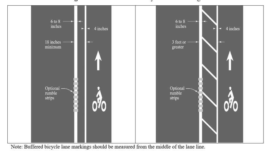
Buffered Bicycle Lanes: Where space is available, bicycle lanes can be improved through the provision of a painted buffer between the bicycle lane and the adjacent motor vehicle lanes and/or a parking lane. They are generally used when traffic volumes include high percentages of trucks or buses and higher travel speeds or to reduce the risk of dooring where bicycle lanes are adjacent to on-street parallel parking.
The lane widths are the same as those set forth in Table 12B-3.05. The buffered bicycle lane provides a greater space for cycling without making the bicycle lane appear so wide that it might be mistaken for a travel or parking lane. The buffer should be a minimum of 18 inches wide and marked with two solid white lines with diagonal hatching or chevron markings if the width is 3 feet or greater. Typical spacing of the chevron markings is 20 feet. The maximum spacing should not exceed the equivalent of the speed limit. Colored markings may be used at the beginning of each block to discourage motorists from entering the buffered lane. The combined width of the buffer(s) and bicycle lane should be considered the “bicycle lane width.” For buffered lanes between travel lanes and on-street parking, the bicycle lane should be a minimum of 7 feet wide (inclusive of buffer width) to encourage bicyclists to ride outside the door zone. Rumble strips may be added to the painted buffer area as an additional indicator for vehicles to remain clear of the bicycle lane. Placement of rumble strips should comply with Iowa DOT requirements. Rumble strips can present a hazard to bicyclists and should not be used in areas where bicyclists are likely to merge in the adjacent general purpose lane to complete turns.
Figure 12B-3.05: Buffered Bicycle Lane Markings
Source: Adapted from Urban Bikeway Design Guide, NACTO
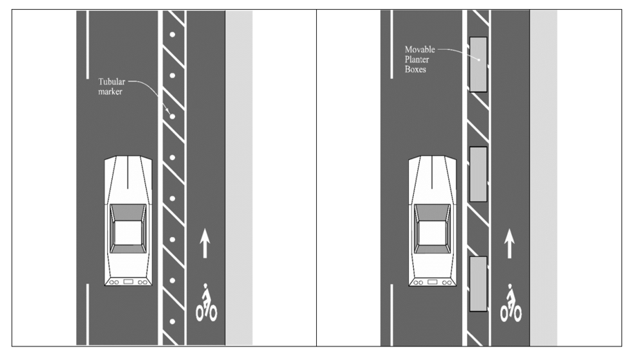
- Separated Bicycle Lanes: In order to feel comfortable riding on high speed and high-traffic streets, most bicyclists prefer separation from motor vehicle traffic, see Section 12B-1. Separated bicycle lanes provide an exclusive space that is physically separated from motor vehicle or parking lanes by a vertical element. Examples of vertical separation include delineators, bollards, curbs, medians, planters, concrete barriers, and on-street parking, see Figure 12B-3.08. Where on-street parking is present, designers may need to evaluate parking restrictions to ensure adequate sight distance, see Section12B-3, E, 9.
Figure 12B-3.08: Separated Bicycle Lane
Source: Adapted from Urban Bikeway Design Guide, NACTO
If the separated bicycle lane is parking protected, parking should be prohibited a minimum of 30 to 50 feet from the crosswalk of an intersection. Make sure to provide ADA access across the separated bicycle lane from parking spaces.
Separated bicycle lanes may be located at street elevation, sidewalk elevation, or an intermediate elevation in between the sidewalk and street. When built at sidewalk level, care must be taken to ensure they are distinct from the sidewalk to discourage pedestrian encroachment and to provide a detectable edge for persons with vision disabilities.
Separated bicycle lanes may be installed in one-way and two-way configurations, each of which present opportunities and challenges that must be considered during the design process. Two-way separated bicycle lanes might be appropriate where key destinations exist along one side of the road, where driveways and intersections are sparse along one side of road but frequent along the other side, or for other context-based reasons. If used, signings and markings at intersections, driveways, and other conflict points should be employed as appropriate to ensure people walking and driving are aware of the two-way operations. At signalized intersections, additional equipment and phasing adjustments may be necessary, see Section 12B-3, L.
Separated bicycle lane width should be selected based on the desired elevation of the bicycle lane, adjacent curb type(s), anticipated volume of users, likelihood of passing maneuvers, and one-way vs. two-way operation. Bicyclists typically do not have the option to pass each other by moving out of a separated bicycle lane as they would in a standard bicycle lane because of the vertical elements between the bikeway and the motor vehicle travel lane. It is therefore preferable for the width of the separated bicycle lane to accommodate passing and potentially allow side-by-side bicycling. The preferred, minimum, and constrained bicycle lane widths for one-way and two-way separated bicycle lane(s) are provided in Table 12B-3.6. When designing separated bicycle lane widths, consideration should also be given to the following factors:
- Shy distances to different curb types and vertical elements (see Table 12B-3.02).
- The equipment that will be needed to perform sweeping and snow removal maintenance. Unobstructed widths of less than 8 feet will likely require specialized maintenance equipment. If a solid median is used as the means of vertical separation, drainage may also be impacted. Separation devices such as delineators or planters may be removed during the winter months to facilitate snow plowing and removal activities.
- Tactile warning devices when level with adjacent sidewalk.
\(^{1}\)The width shown are for separated bicycle lanes where the peak bicycle activity is less than 150 bicycles per hour. Where volumes exceed this, additional width should be provided.
\(^{2}\)In constrained conditions , the minimum widths for separated bicycle lanes will not accommodate passing maneuvers between bicyclists. As such , constrained widths are not recommended for long distances. However , they may be appropriate adjacent to accessible parking spaces , loading zones, or transit stops if sufficient width is not available to accommodate the preferred widths.
Source: Adapted from Minnesota Bicycle Facility Design Manual
Interaction between transit stops and separated bicycle lanes can be difficult. When possible, the bicycle lane should be routed behind the bus platform. Where on-street parking is present, a floating bus stop may be provided, see NACTO’s Transit Street Design Guide. If bus traffic is infrequent (less than four buses per hour), bus stops can utilize the bicycle lane space. When buses are present, bicyclists may merge left and pass the stopped bus.
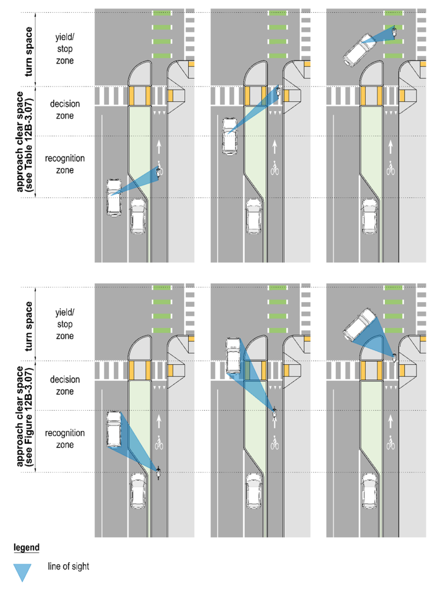
Separated Bicycle Lane Parking Buffer Design for Intersection Sight Distance: When a separated bicycle lane is located adjacent to a parking lane, it may be necessary to restrict parking and other vertical obstructions in the vicinity of a crossing to ensure adequate sight distance are provided for both bicyclists and motorists. To determine parking restrictions near the crossing, it is necessary to know the approach speed of the bicyclist and the turning speed of the motorist. The overall objective of the design is to provide adequate sight distances for each user to detect a conflicting movement of another user and to react appropriately. The approach to the conflict point consists of these three zones:
- Recognition Zone: The approaching bicyclist and motorist have an opportunity to see the other and evaluate their respective approach speeds.
- Decision Zone: The bicyclist or motorist identifies who is likely to arrive at the intersection first and adjusts their speed to yield or stop if necessary.
- Yield/Stop Zone: A space for the motorist or bicyclist to yield or stop, if necessary.
At intersections with permissive turning movements where bicyclists and motorists are traveling in the same direction, there are two yielding scenarios that occur depending upon who arrives at the crossing first. The two scenarios are described below and illustrated in Figure 12B-3.09.
- Right Turning Motorist Yields to Through Bicyclist: This scenario occurs when a through moving bicyclist arrives at the crossing prior to a turning motorist, who must stop or yield to the through bicyclist. Parking must be set back sufficiently for the motorist to see the approaching bicyclist
Through Bicyclists Yields to Turning Motorist: This scenario occurs when a turning motorist arrives at the crossing prior to a through moving bicyclist. Again, parking must be set back sufficiently to enable bicyclists and motorists to see and react to each other.
Figure 12B-3.09: Yielding Scenarios Illustrating Intersection Sight Distance Case A
Source: Adapted from MassDOT Separated Bike Lane Planning & Design Guide
The following provides sight distance considerations for situations where motorists turn right, left, or cross separated bicycle lanes. The recommended approach clear space assumes the bicyclist is approaching the intersection at a constant speed of 15 mph. Clear space recommendations are provided for various turning speeds of motorists that may vary based on the geometric design of the corner and the travel path of the motorist. The recommended clear space allows 1 second of reaction time for both parties as they approach the intersection. If bicyclists’ speeds are slower (such as on an uphill approach) or motorists’ turning speeds are slower than 10 mph, the clear space can be reduced. Where either party may be traveling faster, such as on downhill grades, the clear space may benefit from an extension.
a. Bicycle Case A - Right-Turning Motorist Across Separated Bicycle Lane: In this case, the motorist will be decelerating for the right turn approaching the intersection. Table 12B-3.07 identifies the minimum approach clear space, measured from the point of curvature of the motorist’s effective turning radius, which represents the location where the motorist will have decelerated to the turning speed; this location may or may not be the curb line point of curvature. For locations with two-way separated bicycle lanes, additional approach clear space is not typically required because the recognition zone between the counterflow bicyclist movement and the right-turning motorists should exceed the recommended sight distances. Approach clear space may be increased to account for steeper slopes or higher speeds for bicyclists.
Table 12B-3.07: Intersection Approach Clear Space by Vehicular Turning Design Speed
b. Bicycle Case B - Left-Turning Motorist Across Separated Bicycle Lane: This case applies when a motorist is making a permissive left turn at a traffic signal or from an uncontrolled approach (e.g., a left turn from an arterial onto a local street or driveway). On one-way streets with a left-side separated bicycle lane, this case has the same operational dynamics and approach clear space requirements as Bicycle Case A since the left-turning motorist will be turning adjacent to the separated bicycle lane. On two-way streets with a left-side separated bicycle lane, there are two sight lines that should be maintained. A left-turning motorist approaching a turn needs a line of sight to bicyclists approaching from the same direction. Table 12B-3.07 identifies the minimum approach clear space based on the effective turning radius for the left-turning motorist. The provision of Bicycle Case A for motorists making a right-turn across a two-way bikeway will already provide the necessary line of sight between a left-turning motorist and a bicyclist approaching from the opposite direction.
On streets with two-way traffic flow, the operational dynamic of a motorist looking for gaps in traffic creates unique challenges that cannot be resolved through improving sight distance. This is a challenging maneuver because the motorist is primarily looking for gaps in oncoming motor vehicle traffic and is less likely to scan for bicyclists approaching from behind. Unlike for Bicycle Case A or Bicycle Case B on one-way streets where the motorist is decelerating towards the crossing, the motorist in this case will be accelerating towards the crossing once they perceive a gap in traffic. This creates a higher potential for conflicts on roads with the following:
- High traffic volumes and multiple lanes.
- Higher operating speeds.
- High left turn volumes.
Where it is not feasible to eliminate high speed and high volume conflicts through signalization, turn prohibitions, or other traffic control, it may be necessary to reevaluate whether a two-way separated bicycle lane is appropriate at the location, or provide an adequate motorist yield zone that allows the motorist to complete the turn while still yielding to crossing pedestrians or bicyclists, see Section 12B-3, F, 5.
c. Bicycle Case C - Motorist Crossing of a Separated Bicycle Lane or Shared Use Path: This case applies when a motorist crosses a separated bicycle lane and is similar to the cases in the AASHTO Bicycle Guide where a motorist crosses a bicycle lane or a mid-block path. The bicycle lane case is expanded upon below, including near-side and far-side intersection scenarios.
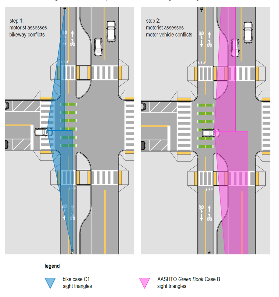
- Bicycle Case C1 - Near-Side Crossing: This case applies when a motorist crosses a near-side separated bicycle lane before continuing straight or turning at an intersection. The two potential design scenarios are as follows:
Two-Stage Crossing: In this scenario, the motorist will first assess the bicycle conflicts, then move forward and assess motor vehicle conflicts (i.e., designers should perform two calculations from two different locations) as shown in Figure 12B-3.10. Similar to when a motorist moves forward after assessing pedestrian conflicts, when the motorist moves forward, they might block the bikeway to look for gaps in traffic. The equation in Table 12B-3.08 should be used to calculate the departure sight triangle between a passenger vehicle and the bikeway using a time gap (tg) of 5.5 seconds for the motorist to clear the bikeway. This time gap uses an assumption that the vertex (decision point) of the departure sight triangle is 10 feet from the edge of bikeway and the bikeway width is no wider than 14 feet. The appropriate sight distance from AASHTO Green Book Case B should then be used to calculate departure sight triangle between the motorist and the intersecting motorist travel lanes.
Figure 12B-3.10: Bicycle Case C1 - Two-Stage Crossing Scenario
Use the following equation to determine the Bicycle Case C intersection sight distance.
Equation 12B-3.01
\(ISD_{bike} = 1.47 V_{bike} t_g\)
Where,
\(ISD_{bike}\) = Intersection sight distance (length of the leg of sight triangle along the bikeway ) (ft)
\(V_{bike}\)= Design speed of bike (mph)
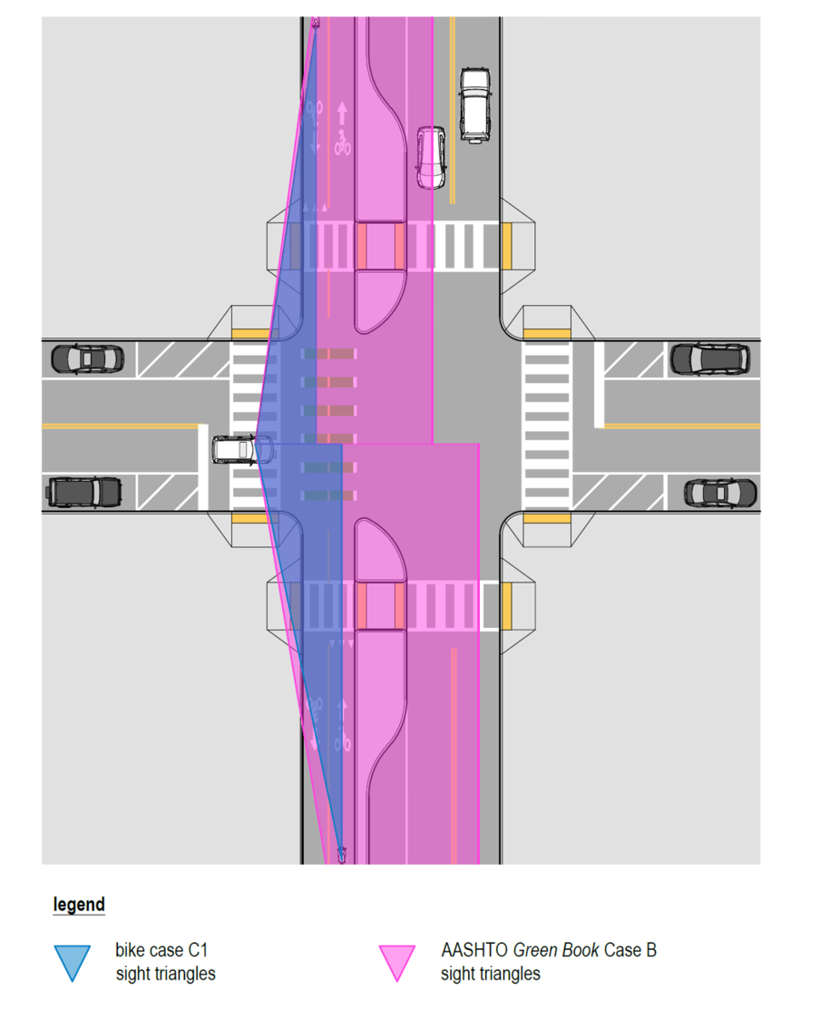
Single Crossing: In this scenario, the motorist assesses both the bikeway conflicts and motor vehicle conflicts from one stopped location, then performs the turning movement when there is a sufficient gap in both the bikeway and motor vehicle traffic (Figure 12B-3.11). This scenario may be appropriate in locations where the motorist would otherwise block the bicycle facility for extended periods of time or where bicycle volumes or motorist volumes are anticipated to be high. The equation in Table 12B-3.08 should be used to calculate the departure sight triangle between a passenger vehicle and the bikeway using a time gap (tg) of 4 seconds for the motorist to clear the bikeway. This time gap uses an assumption that the vertex (decision point) of the departure sight triangle is 10 feet from the edge of bikeway and the bikeway width is no wider than 14 feet. The vertex of the departure triangle between the motorist and the intersecting motorist travel lanes will remain the same, but designers will need to adjust the typical time gap for the appropriate sight distance from AASHTO Green Book Case B to account for the longer distance the motorist will traverse. As shown in Figure 12B-3.11, the provision of the motorist intersection sight distance will often accommodate the sight distance along the bikeway.
Figure 12B-3.11: Case C1 - Single-Stage Crossing Scenario
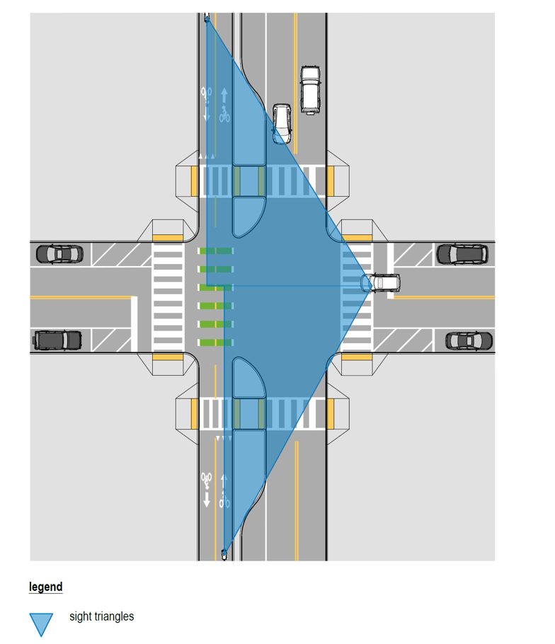
- Bicycle Case C2 - Far Side Crossing: This case applies when a motorist crosses a far side separated bicycle lane, see Figure 12B-3.12. Where both the motorist and bikeway approaches are stop-controlled, providing a line of sight between the stopped motorist and the stopped bikeway user is appropriate.
Where the motorist approach is stop-controlled and the bikeway crossing is uncontrolled, the intersection sight distance described in AASHTO Green Book Case B3 should be used to calculate departure sight triangle between the motorist and the intersecting bikeway. The bikeway design speed should be used in the intersection sight distance triangle calculation. The bikeway width and street buffer width should be converted to equivalent lane widths to adjust the time gap (tg) for the crossing of the roadway and the bikeway. In constrained situations, at a minimum, the stopping sight distance for bicyclists should be provided to allow a bicyclist to slow or stop if a vehicle encroaches into the bikeway.
As with Bicycle Case B, this case creates a challenging dynamic that is often difficult to resolve by increasing the size of the sight triangle. In urban areas, it may be difficult to increase the sight triangle enough to provide the intersection sight distance to judge gaps that allow a motorist to cross all the travel lanes as well as the separated bicycle lane on the opposite side of the road. As such, designers should consider the frequency of through movements at these types of intersections and provide either traffic control devices or adequate sight distance (i.e. minimum stopping sight distance) for bicyclists to see and react to a crossing vehicle and stop if necessary. It may be appropriate to restrict these through motorist movements where traffic control devices or sight distances are inadequate.
Figure 12B-3.12: Bicycle Case C2 - Single-Stage Crossing Scenario
Curbside Management, Accessible Parking, and Loading Zones: At locations where vehicles frequently stop or stand in the bicycle lane, in addition to the signing strategies noted above, it may be beneficial to implement curbside management strategies to result in increased parking and loading space availability during peak periods and to address various curbside uses. Where on-street parking is present, loading zones may be delineated within the parking lane, and the bicycle lane may be preserved alongside them. See the ITE Curbside Management Practitioners Guide for more information.
Accessible parking and loading spaces require additional space adjacent to parking stalls for vans with ramps to allow passenger boarding and alighting, and to ensure an accessible route is provided to and from the sidewalk. This can present a unique challenge when separated bicycle lanes are present between the on-street parking and sidewalk. In constrained locations where accessible parking is provided, the protected bicycle lane may be narrowed to a minimum constrained width adjacent to the parking. It is preferable to use a raised crossing such that the separated bicycle lane is an intermediate or sidewalk level thus reducing the risk of pedal strikes. In addition, this may slow bicyclists down and reinforce that pedestrians will be crossing at this location. At locations without on-street parking but where an accessible parking or loading area is desired, a lateral deflection (bend-out) of the separated bicycle lane will often be required to accommodate the accessible space. Bicycle lane deflection should occur gradually but should not exceed the shifting taper guidelines to maintain bicyclist safety and comfort.
F. Intersection Design
Due to the vulnerability of bicyclists as well as the low visibility the bicyclists have in relationship to the motorists, good intersection bicycle lane design and intersection pavement marking design is crucial to the success of an intersection that incorporates bicycle lanes. As a bicycle lane approaches an intersection, designers should provide a continuous and direct route through the intersection, driveway, or alley that is legible to all users of the roadway. Designers should minimize or eliminate conflict areas between bicyclists and motor vehicles, where possible. To minimize the potential for conflicts, designers should adhere to the following design principles:
- Designers should communicate where motorists are expected to yield to bicyclists (e.g., markings and signage).
- Bicycles should not operate between turning lanes and moving lanes with traffic operating over 30 mph on either side of them for distances longer than 200 feet.
- Bicycle crossings of weaving or merging movements by motor vehicles operating over 20 mph should be avoided or minimized to a length of 200 feet or less.
- It is preferable for motorists merging and crossing movements across bicycle lanes be confined to a location where motor vehicles are likely to be traveling at speeds less than 20 mph.
- It is preferable for bicycle crossings of intersections to be marked.
A conventional or buffered bicycle lane can be transitioned to a protected bicycle lane and follow the design of a protected intersection to increase the comfort of the bikeway at the intersection. Designers should consider this design as operating speeds reach 35 mph or higher. When a protected intersection is not feasible for operating speeds of 35 mph or greater or motor vehicle turning volumes exceed 150 turning vehicles per hour, a bicycle ramp should be considered to give bicyclists a choice to exit the roadway to a shared use path or sidewalk prior to the intersection, see Section 12B-3, Q for bicycle ramp design parameters.
Where conflicts occur, intersection treatments like bicycle boxes, protected intersections, and bicycle signals can improve the safety, visibility, and/or comfort of bicyclists. Where conflict areas are present, pavement markings and signage should be used as speeds and volumes increase to improve legibility and safety. Bicycle crossing or lane extension lines, two stage turn boxes, and bicycle boxes may include an optional green pavement paint. If used, the green pavement paint must meet the MUTCD “Interim Approval for Optional Use of Green Colored Pavement for Bicycle Lanes (IA-14).” Because drivers and bicyclists in Iowa may not be familiar with the use of bicycle boxes and bicycle signals, it is critical to provide extensive educational information prior to implementing either of these strategies at urban intersections.
- Shared Through/Right Motor Vehicle Lane: When bicycle lanes are present on two-lane roadways, bicycle lane lines may be solid or dotted on the approach to and within intersections where motor vehicles are allowed to enter a bicycle lane to prepare for a turning, crossing, or merging maneuver. A solid line may be appropriate where turning volumes are low. At intersection approaches with limited space where a right-turn lane is not required but there are relatively high right-turn volumes (more than 150 vehicles during the peak hour) or an existing crash history, designers should consider converting the conventional bicycle lane to a separated bicycle lane by adding a 2 foot minimum buffer with flexible delineator posts beginning at least 50 feet in advance of the intersection to provide added comfort for bicyclists, slow the speed of turning motorist, and reduce the conflict area. Signal phase separation of bicyclists and motorists should be considered, but if concurrent movements are allowed, a bicycle box or forward bicyclist queuing area should be considered.
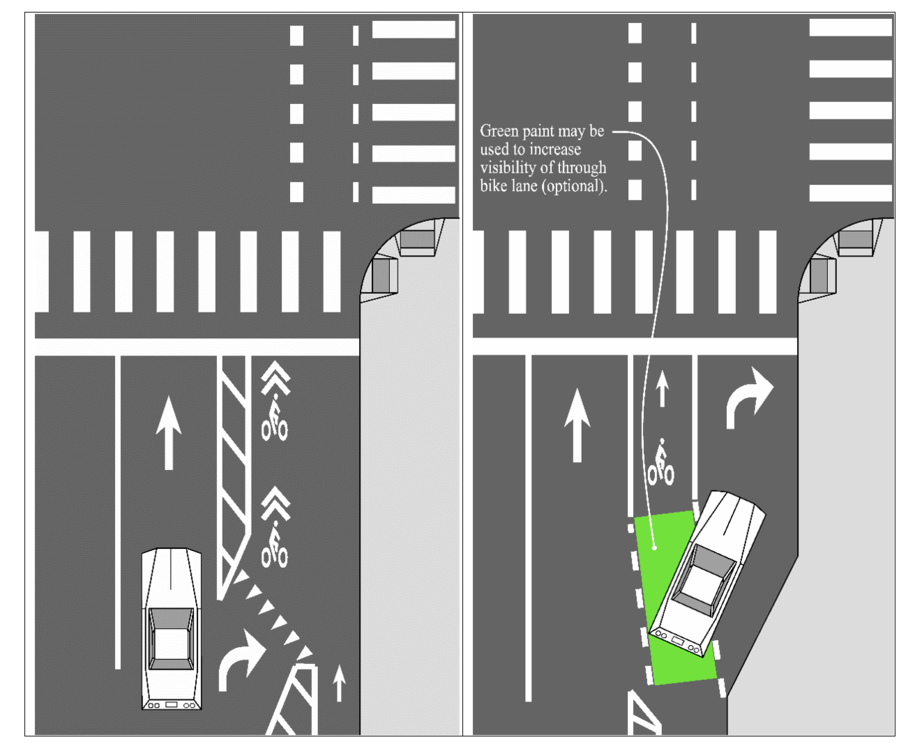
- Right Turn Only Lanes: Where right turn lanes are introduced and conventional or buffered bicycle lanes are present, the through bicycle lane should be shifted to the left of the right turn lane and markings and signage should clearly indicate conflict areas. Merging areas should be minimized and should not exceed 200 feet to limit the conflict area. Depending on how a turn lane is introduced (e.g., in the parking lane, intersection widening, etc.), designers should refer to Section 12B-3, A, for the design of the lateral shift of the bicycle lane to a position to the left of the right turn lane; see Figure 12B-3.13. See Section 12B-3, F, 4 for conflict marking recommendations. Dual right turn only lanes should be avoided on streets with bicycles. If dual right turn lanes are necessary to accommodate heavy right-turn volumes, a designer should transition the bicycle lane to a separated bicycle lane or shared use path in advance of the intersection. The high right turn volumes will require the provision of a separate bicycle crossing phase; see Section 12B-3, L.
Bicycle Ramps and Mixing Zones: On roadways with operating speeds over 35 mph, or at locations where right turn lanes exceed 200 feet in length, designers should consider providing a bicycle ramp to allow bicyclists to exit the roadway to an off-street bikeway or sidewalk prior to the merge area; see Section 12B-3, Q for the design of bicycle ramps. On lower speed roadways where there is insufficient width to maintain a bicycle lane through the intersection, a mixing zone may be appropriate. A mixing zone is an area at an intersection where the bicycle lane becomes a shared lane with the turning vehicles; see Figure 12B-3.13. For separated bicycle lanes, the vertical element should be discontinued prior to the location motorists are expected to merge into the shared bicycle and right turn only lane. Merging area and turn lane length should both be minimized (each to a maximum of 200 feet) to limit the conflict area. Sharrow markings are used to guide the bicyclists from the bicycle lane through the intersection.
Figure 12B-3.13: Mixing Zones and Through Bicycle Lane
Source: Adapted from Urban Bikeway Design Guide, NACTO
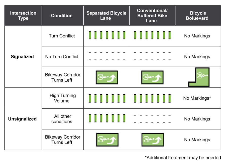
Intersection Pavement Markings: Intersection pavement markings are used to highlight conflict areas and aid bicyclist navigation. Figure 12B-3.14 summarizes the preferred pavement markings based on the intersection and bikeway type.
Figure 12B-3.14: Bicycle Crossings and Intersection Marking Selection Guidelines
Source: Adapted from Ohio DOT Multimodal Design Guide
Bicycle crossing Markings / Lane Extension Lines: Where a bikeway crosses an intersection separate from a crosswalk, bikeway lane markings may be extended through the intersection to delineate the bicycle crossing and raise awareness of the presence of bicyclists. Bicycle lane crossings are desirable to:
- Delineate a preferred path for people bicycling through the intersection, especially crossings of wide or complex intersections;
- Improve the legibility of the bicycle crossing to roadway users; and
- Encourage motorist yielding behavior, where motorists must merge or turn across the path of a bicyclist.
Bicycle crossings may also be supplemented with green colored pavement. If used, the green colored pavement should align with the dotted extension line pattern of the dotted edge lines.
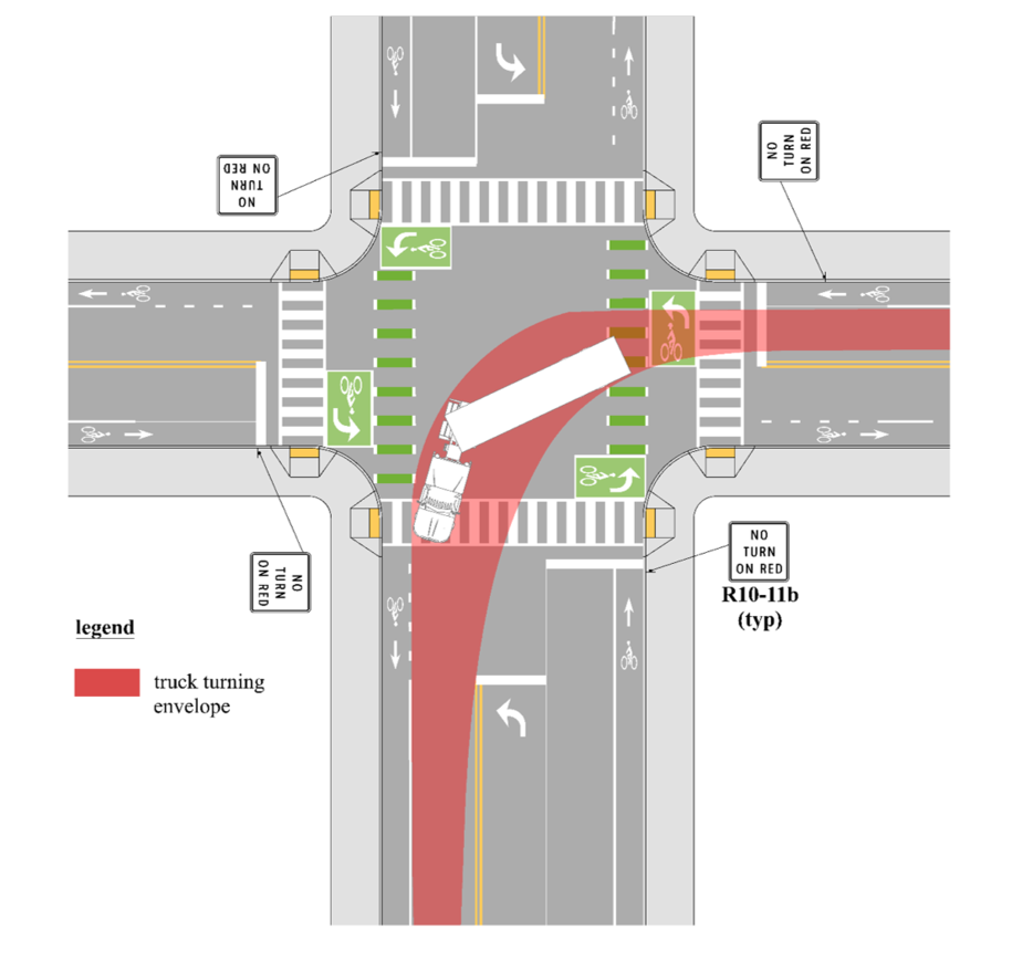
Two-Stage Turn Boxes: Weaving across travel lanes and merging with motor vehicle traffic to reach the left side (or right side when the bicycle lane is located on the left-hand side of a one-way street) of the street is challenging for most bicyclists. Where there are high volumes of left-turning bicyclists, or where a designated or preferred bicycle route requires a left turn, a provision for left-turning bicyclists should be provided. This can generally be accomplished by providing a two-stage turn box, which has interim approval in the MUTCD (IA-20).
With the two-stage bicycle turn box, bicyclists traverse the intersection within the bicycle lane, stop within the turn box, reorient themselves to the cross street, and wait for the green signal for the cross street to proceed, eliminating the need to merge across travel lanes, see Figure 12B-3.15. It may be used for left or right turns (e.g., where a bicycle lane is placed on the left side of a one-way street). It may be used at any signalized intersection but is preferable on high volume and multilane roads.
A two-stage bicycle turn box must be located outside of the path of through and turning traffic; should be located adjacent to, preferable to the right of, the direct path of bicyclist travel; and should be located downstream of the crosswalk and downstream of the stop line. It must include a bicycle symbol and a turn arrow to clearly indicate proper direction and positioning.
Figure 12B-3.15: Two-Stage Bicycle Turn Box Placement
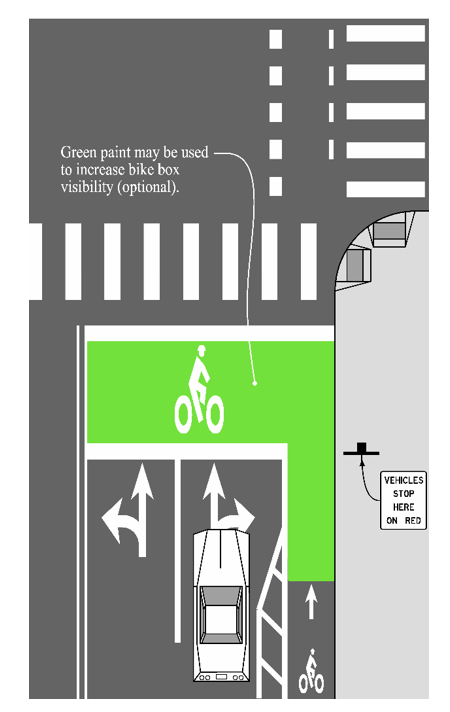
Bicycle Box: Bicycle boxes, which have interim approval in the MUTCD (IA-18), are placed between the vehicle stop line and the pedestrian crosswalk; see Figure 12B-3.16. Bicycle boxes increase the visibility of bicyclists to motorists, provide an advance queuing area to store larger numbers of bicyclists, and reduce bicyclist encroachment into crosswalks during the red signal phase. Bicycle boxes are limited to signalized intersections. Bicycle box are typically formed by two transverse lines, typically 10 to 16 feet deep and the combined width of the bicycle lane, the buffer space, and all of the adjacent same direction traffic lanes at the intersection.
In limited situations, bicycle boxes may be used to facilitate left turns for bicyclists when there is unusually heavy left turn volume of bicyclist, such as near the entrance to a popular shared use path. Research shows the use of bicycle boxes to make left turns is limited in practice; the preferred treatment is the two-stage bicycle turn box.
Figure 12B-3.16: Bicycle Box
Source: Adapted from Urban Bikeway Design Guide, NACTO
Protected Intersections: A major goal in providing separated bicycle lanes is to minimize conflicts between bicyclists, pedestrians, and motorists at intersections. For this reason, it is preferable to maintain separation between the separated bicycle lane and the adjacent motor vehicle travel lanes at intersections. Protected intersections provide a design that maintains separation between modes and can work for intersections of separated bicycle lanes and Type 1 shared use paths. The following discussion focuses on design guidance for the geometric elements of a protected intersection for separated bicycle lanes and shared use paths (See Figure 12B-3.17).
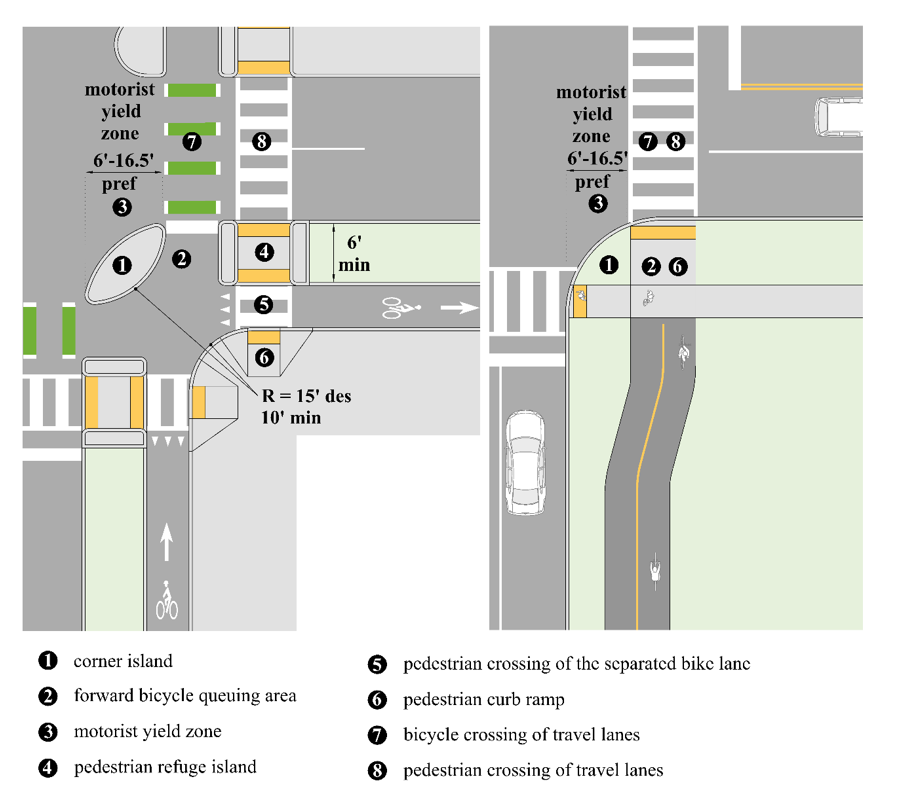
Figure 12B-3.17: Protected Intersection Design for Separated Bicycle Lanes and Shared Use Paths
Source: Adapted from MassDOT Separated Bike Lane Planning & Design Guide
Corner Island: The corner island (labeled as 1 in Figure 12B-3.17) allows the bicycle lane or shared use path to be physically separated up to the intersection crossing point where potential conflicts with turning motorists can be controlled more easily. It also creates space for a forward bicycle queuing area, creates additional space for vehicles to wait while yielding to bicyclists and pedestrians who are crossing the road, reduces motorist turning speeds; and can reduce through bicyclist speeds by adding deflection to the bicycle lane or shared use path.
Corner islands may be constructed of concrete and curbing, or may be constructed with low cost materials, such as paint and flexible delineator posts or engineered rubber curbs and/or rubber speed cushion. If a corner island is constructed of mountable materials, such as rubber speed cushions, designers should understand the forward queuing area for bicyclists and pedestrian crossing islands may no longer be protected from turning motorists and should therefore be removed. Where flex posts or other vertical elements are used, they should be placed at least 1 foot offset from the turning radius of design vehicles at all intersections and driveways.
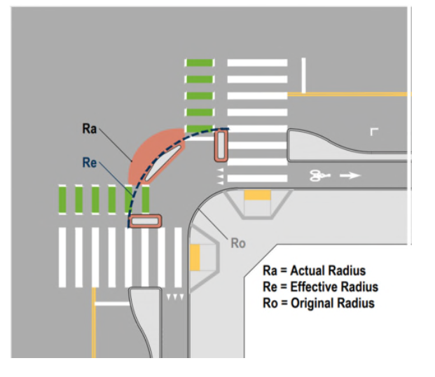
Truck Apron: A truck apron is a design strategy used to accommodate the turning needs of large vehicles while slowing the turning speeds of smaller vehicles by reducing the actual radius. A truck apron is designed to be mountable by larger vehicles to accommodate their larger effective turning radius needs. The mountable surface encourages the design vehicle, typically a passenger (P) or delivery vehicle (SU-30), to turn without using the apron and reduces their effective turning radius and speed.
Figure 12B-3.18: Actual vs Effective Radius
Source: City of Des Moines’ Bike Guide
Truck aprons can be installed with corner reconstruction or in a retrofit condition. They can be constructed with a gap between the mountable curb and the curb face to facilitate surface drainage, if necessary.
For constructability and visibility, truck aprons have a minimum size requirement to be effective. Where the distance between the effective radius and the actual radius is less than 5 feet, truck aprons are not feasible. A smaller distance will become difficult to visually differentiate from the surrounding surfaces and may be more difficult to construct.
Truck aprons that are too large may similarly not be effective at communicating the use of the space, which may be confusing to motorists and people trying to navigate the intersection. Where the distance between the effective radius and the actual radius is greater than 15 feet, truck aprons are not recommended. This situation can be found in intersections where full reconstruction of the intersection should be considered.
Designers should consider the following guidance when implementing a truck apron:
- The pavement color and texture within the truck apron should be distinct from the adjacent roadway and sidewalk.
- Reflective raised pavement markers should be used at the actual radius to ensure the path of travel is visible at night. Retroreflective lane edge line striping should also be provided.
- Channelizing pavement markings may be installed on the mountable truck apron to discourage use of the space by smaller vehicles.
- A truck apron should have a mountable section between 2 and 3 inches high when the control vehicle represents less than 5% of the total turns at an intersection.
- When the control vehicle represents more than 5% of the total turns at an intersection, or where both cross streets are served by frequent transit, a truck apron with a 1 to 2 inch height mountable section may be used.
- Forward Bicycle Queuing Area: The forward bicycle queuing area is a waiting area for stopped bicyclists (labeled as 2 in Figure 12B-3.17). The area is fully within view of motorists who are waiting at the stop bar (if present), which improves bicyclist visibility. Ideally, the bicycle queuing area should be at least 6 feet long to accommodate a typical bicycle length.
- Motorist Yield Zone: The motorist yield zone is a bicycle and pedestrian crossings set back from the intersection to create space for turning motorists to yield to bicycles and pedestrians (labeled as 3 in Figure 12B-3.17). The offset improves motorist view of approaching bicycles by reducing the need for motorists to scan behind them and potentially creates space for a motorist to yield to bicyclists and pedestrians without blocking traffic.
- Pedestrian Refuge Median: The pedestrian refuge median is a space where pedestrians may wait between the street and the separated bicycle lane (labeled as 4 in Figure 12B-3.17). It should be a minimum width of 6 feet and should include detectable warning surfaces. A pedestrian refuge median allows pedestrians to negotiate potential bicycle and motor vehicle conflicts separately, improves visibility of pedestrians to motorists approaching the intersection, shortens the pedestrian crossing distance, and reduces the likelihood of pedestrians blocking the bicycle lane.
- Pedestrian Crossing of the Separated Bicycle Lane: Where pedestrians are expected to cross separated bicycle lanes, crosswalks (labeled as 5 in Figure 12B-3.17) indicate a preferred crossing location and communicate a clear message to bicyclists that pedestrians have the right-of-way. Yield lines and YIELD HERE FOR PEDESTRIANS signs in the bicycle lane in advance of the crosswalk may be used to emphasize pedestrian priority.
- Pedestrian Curb Ramp: Curb ramps and detectable warning surfaces (labeled as 6 in Figure 12B-3.17) should meet pedestrian accessibility guidelines. It is preferable to use the curb ramp style that will shorten crossing distances and provide directional cues to pedestrians.
- Bicycle Crossing of Travel Lanes: For separated bicycle lanes, bicyclists cross the motorist travel lane between the motorist yield zone and pedestrian crossing. For shared use paths, bicyclists cross with pedestrians in the pedestrian crossing (labeled as 7 in Figure 12B-3.17). Bicycle crossings for separated bicycle lanes are often striped using bicycle crossing markings and should be striped using crosswalks for shared use paths.
- Pedestrian Crossing of Travel Lanes: Pedestrians cross the motorist travel lane behind the motorists yield zone and behind bicycle crossings when present (labeled as 8 in Figure 12B-3.17).
- Traffic Signals and Bicycle Signals: Special signal timings and bicycle signal heads may be used at intersections to separate bicycle through movements from vehicle movements for increased safety. More detailed guidance on traffic signals for bicycle facilities is found in Section 12B-3, L.
G. Retrofitting Bicycle Facilities on Existing Roadways
Existing streets and highways may be retrofitted to improve bicycle accommodations by either reconfiguring the travel lanes to accommodate bicycle lanes or by widening the roadway to accommodate bicycle lanes or paved shoulders. These retrofits are best accomplished as either a reconstruction project or a repaving project as these projects will eliminate traces of old pavement markings. (AASHTO Bicycle Guide 4.9).
Figure 12B-3.19: Example of Road Diet
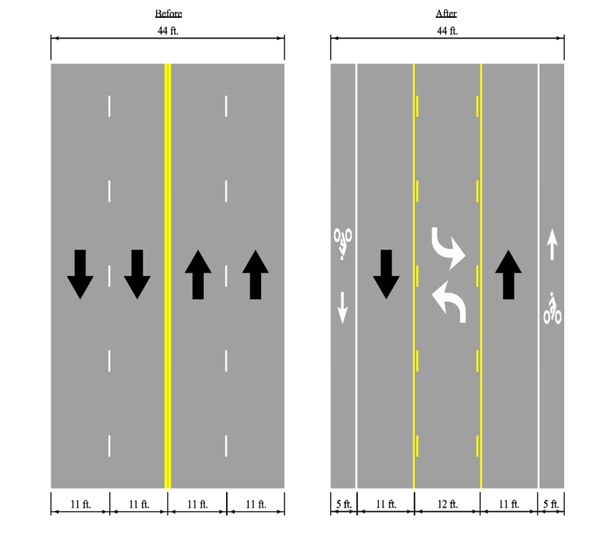
* Dimensions are illustrative
Source: Adapted from AASHTO Bicycle Guide Exhibit 4.23
Back to topH. Bicycle Boulevards
A bicycle boulevard is described as a local street or a series of contiguous street segments that have been modified to function as a through street for bicyclists while discouraging through vehicle traffic. To be effective, bicycle boulevards should be long enough to provide continuity over a distance of between 2 and 5 miles. Section 12B-1 provides additional guidance on when bicycle boulevards are an appropriate bicycle facility.
Due to the low traffic volumes and speeds, local streets naturally create a bicycle-friendly environment for bicyclists to share the roadway with vehicles. However, many local streets are not continuous enough for long bicycle routes. Therefore, in order to create a bicycle boulevard, some short sections of paths or segments may need to be constructed between local streets in order to create the continuous route. The following three principles should guide bicycle boulevard planning and design:
- Manage Motorized Traffic Volumes and Speeds: To minimize conflicts and the frequency of motorists passing bicyclists, bicycle boulevards should meet the guidelines of Table 12B-3.09 for daily and hourly motor vehicle volumes and operating speeds:
Table 12B-3.09: Bicycle Boulevard Motorized Traffic Volume and Speed Performance Criteria
\(^{1}\) Assumed to be 15% of ADT
Source: Based on NACTO Urban Bikeway Design Guide
The design of the street should result in the preferred motorist volumes and operating speeds being achieved at all times of the day. Where daily or peak hourly traffic volumes or traffic speeds exceed the maximum guidelines, traffic calming or traffic diversion strategies should be considered. Traffic diverters are treatments that allow bicycle through traffic but reduce or deny vehicle traffic.
- Prioritize Right-of-way at Local Street Crossings: Along bicycle boulevards, most of the intersections a bicyclist will cross will be local streets crossing other local streets. For bicycle boulevards to serve as efficient routes for longer distance travel, they should minimize the need for bicyclists to stop at crossings of local streets. Consider the following elements:
- Two-way stop-controlled intersection that give the bicycle boulevard priority
- Neighborhood traffic circles or mini roundabouts
- Provide Safe and Convenient Crossings at Major Streets: Major street crossings along bicycle boulevards can be significant barriers. Treatments such as median refuge islands, beacons, and signals should be installed to accommodate bicyclists crossing.
I. Bicycle Guide Signs
Guide signs are an important element to all bicycle facilities because they help bicyclists navigate to their destination. There are many guidelines and standards that go along with the type and placement of guide signs. See both the MUTCD and AASHTO Bicycle Guide 4.11.
Back to topJ. Railroad Crossings for Bicycles
Where roadways or shared use paths cross railroad tracks on a diagonal, the designer should take care in the design of the crossing as to prevent steering difficulties for the bicyclists. This includes:
- Increasing the skew angle between the tracks and the bicycle path to 60 degrees or greater so bicyclists can avoid catching their wheels in the flange of the tracks. This can be accomplished with reverse curves or with a widened shoulder.
- Creating a smooth crossing surface that will last over time and not be slippery when wet.
- Minimizing flange openings as much as possible. Under special rail conditions, rubber fillers products may be used. Contact the railroad company for approval prior to the design and installation of the fillers.
See both the MUTCD and AASHTO Bicycle Guide 4.12.1.
Back to topK. Obstruction Markings for Bicycle Lanes
The design of bicycle facilities should avoid obstruction and barriers as much as possible. However, in rare circumstance when an obstruction or barrier cannot be avoided, signs, reflectors, and markings should be used to alert they bicyclists. (AASHTO Bicycle Guide 4.12.2).
Back to topL. Traffic Signals for Bicycles
Traffic signals have traditionally been designed based off the operating characteristics of motor vehicles. At intersections where shared lanes, bicycle boulevards, or bicycle lanes are present, traffic signal designers should include the characteristics of bicyclists to their traffic signals. The signal parameters that should be evaluated are minimum green interval, total phase length, and extension time. This information can be found below in 12B-3, L, 2, in AASHTO Bicycle Guide 4.12.3 and 4.12.4, as well as the latest edition of the “Highway Capacity Manual.”
In addition, designers should ensure signals are actuated, the existing signal detection can reliably detect the presence of bicyclists in a shared lane, and detection is provided for bicycle lanes. Additional markings and signage should be considered as needed for bicyclists to position themselves within the detection zone in shared lanes; see MUTCD 9C.05.
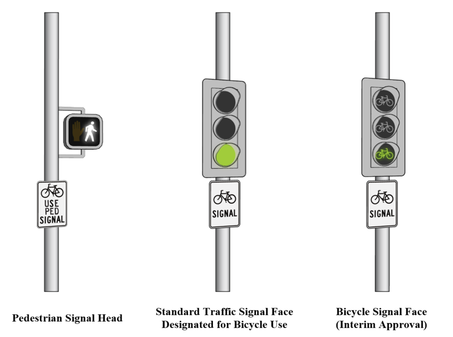
- Traffic Signal Indication Options for Bicycles. A bicyclist traveling in a shared lane is controlled by the vehicular signal head. Where it is necessary or desirable to control a bicycle operating in a separated bicycle lane independently from a motor vehicle, a bicyclist may be controlled by a pedestrian signal head, a traffic signal head designated for bicycle use, or a bicycle signal face. Each of these three options are shown in Figure 12B-3.20 and briefly discussed below. Along a corridor, it is recommended that traffic signal indications for bicyclists are consistent and as uniform as possible.
- Pedestrian Signal Heads: Some agencies direct bicyclists to follow pedestrian signal indications when bicyclists are operating in a separated bicycle lane in the roadway and bicyclists cannot see vehicle signal faces, or when bicyclists have a separate signal phase from motor vehicle movements. To do this, the BIKES USE PED SIGNAL sign (MUTCD R9-5) should be mounted adjacent to the pedestrian signal heads.
- Standard Traffic Signal, Designated for Bicycle Use: A standard traffic signal face may be designated exclusively for bicyclists by mounting a BICYCLE SIGNAL sign (MUTCD R10-10b) adjacent to the traffic signal. This may be beneficial where bicyclists cannot see existing vehicle signal faces, where they have a separate signal phase, or where it is desired to maximize the time a bicyclist may legally enter an intersection.
Bicycle Signal Heads (Interim Approval): Bicycle signal heads use the traditional green, yellow, and red indications but have bicycle stenciled lenses. A supplemental “Bicycle Signal” plaque should be added below the bicycle signal head. Bicycle signal faces currently have interim approval for situations where there are no conflicting motor vehicle movements with the signalized bicycle movement.
Figure 12B-3.20: Examples of Signal Indication Options for Bicyclists
Source: Adapted from MassDOT Separated Bike Lane Planning & Design Guide
- Traffic Signal Phasing and Timing for Bicyclists:
- Signal Phasing: Several signal phasing schemes can be used to reduce conflicts or reinforce bicyclists’ and motorists’ responsibility to yield:
- A flashing yellow right turning arrow and flashing bicycle signal to reinforce yielding where the bicycle phase is concurrent with permissive motor vehicle turns.
- A leading bicycle signal phase, which provides 3 to 5 seconds of green time before the corresponding vehicle green indication.
- A concurrent protected bicycle phase, which runs concurrently with parallel through-vehicle phases, but conflicting vehicle turns across the bikeway are restricted.
An exclusive bicycle phase, in which all vehicle movements are restricted.
The decision to provide a protected phase or a leading bicycle interval for a separated lane or shared use path (see Section 12B-2) should be based on a need to eliminate or manage conflicts and improve safety at an intersection. The potential for conflict at a given intersection is evaluated using the volume of turning motor vehicles crossing the bikeway. Table 12B-3.10 provides peak hourly volume thresholds for turning motor vehicle traffic crossing a bikeway to determine when a protected phase or leading bicycle interval should be considered.
Table 12B-3.10: Hourly Turning Traffic Thresholds for Time-Separated Bicycle Movements
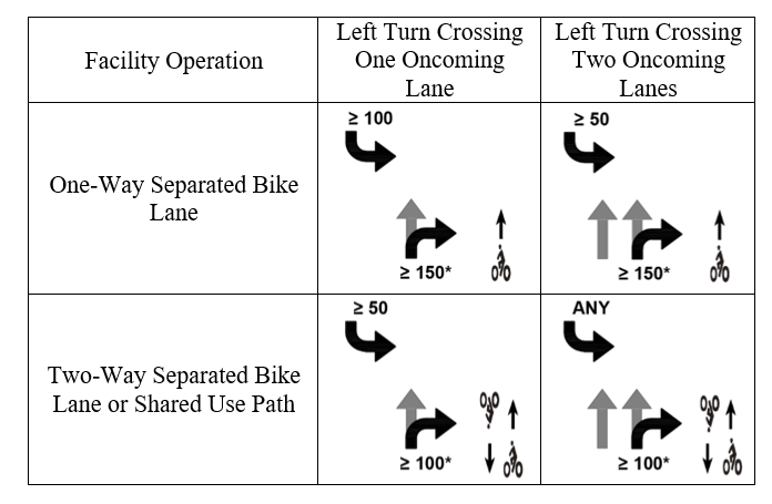
* Threshold also applies to left turns on one-way streets
Source: Adapted from MassDOT Separated Bike Lane Planning and Design Guide
- Signal Timing: Practitioners should consider the operating characteristics for bicyclists when calculating minimum green, yellow change, and red clearance interval design, which in most cases are determined by signal timing requirements for higher speed motor vehicles. A design speed of 8 mph and acceleration of 2.5 ft/s2, which is the speed and acceleration of a slow moving adult bicyclist, is recommended.
- Bicycle Minimum Green: In many cases, the existing vehicle minimum green will not be adequate for a bicyclist. Vehicle minimum green types, ranging between 4 and 15 seconds, are based primarily on driver expectancy and queue clearances. With a 4 second minimum green (not uncommon for a minor street approach), a typical adult bicyclist only has time to react and begin accelerating, traveling less than 10 feet. A minimum green time based on a bicyclist traveling halfway across the intersection will typically result in a phase length long enough for a bicyclist to fully clear the intersection before the conflicting approach receives the green indication. However, at some wider crossings, the minimum green time may need to be longer.
- Signal Phasing: Several signal phasing schemes can be used to reduce conflicts or reinforce bicyclists’ and motorists’ responsibility to yield:
Table 12B-3.11: Bicycle Minimum Green Time
\(G_{min} = t + \frac{1.47v}{2a} + \frac{d + L}{1.47v}\)
where,
\(G_{min}\)= bicycle minimum green time ,s
v= attained bicycle crossing speed , assumed 8 mph
t=perception reaction time, assumed 1.5 s
a=the bicycle acceleration , assumed 2.5 ft/\(s^2\)
d=distance from stop bar to middle of the intersection ,ft
L= typical length of a bicycle, assumed 6 ft
- Total Phase Length: Depending upon intersection width, change, and clearance intervals, the total phase time may not be sufficient for a bicyclist to clear the far side of the intersection before the conflicting approach receives the green indication. After the minimum green time is calculated based on the following equation, it should be evaluated to verify that the total phase time is greater than the total time for a bicyclist starting from a stop to cross the intersection. The minimum green time should be increased until the total phase time is equal to or greater than the total time for a bicyclist to cross the intersection.
\(G_{min} + Y + R_{clear} \ge t + \frac{1.47v}{2a} + \frac{W + L}{1.47v}\)
where,
\(G_{min}\)= bicycle minimum green time, s
Y= yellow change interval, s
\(R_{clear}\)= all red interval, s
W = intersection width, ft
L = typical length of a bicycle, assumed 6 ft
v = attained bicycle crossing speed, assumed 8 mph
t = perception reaction time, assumed 1.5 s
a = bicycle acceleration, assumed 2.5 ft/s2
Back to top
M. Bridges and Viaducts for Bicycles
Two considerations should be considered before the design of bicycle accommodations with bridges - the length of the bridge and the design of the approach roadway. If the bridge approach does not include bicycle accommodations, the bridge can still facilitate use by bicyclists by including a wide shoulder or bicycle lanes and including paved shoulders, shared lanes, or a shared use path as part of the bridge project. Additionally, if the bridge is continuous and spans over a 1/2 mile in length with speed of excess of 45 mph, a concrete barrier separated shared use path on both sides of the bridge should be considered. By allowing paths on both sides of the bridge, wrong-way travel of the bicyclists will be deterred. (AASHTO Bicycle Guide 4.12.5).
Back to topN. Traffic Calming and Management of Bicycles
There are many things a designer can do to reduce the traffic speed of bicyclists and to manage bicycles effectively. These things include: narrowing streets to create a sense of enclosure; adding vertical deflections such as speed humps, speed tables, speed cushions, and raised sidewalks; adding curb extension or chokers; adding chicanes; installing traffic circles; and incorporating multi-way stops. (AASHTO Bicycle Guide 4.12.6 and 4.12.7).
Back to topO. Intake Grates and Manhole Castings for Bicycle Travel
Intake grate openings should run perpendicular to the direction of travel to prevent bicycle wheels from dropping into the gaps and causing crashes. SUDAS Specifications Figure 6010.603, Type R and Type S, are intake grates appropriate for use on bicycle routes. Where it is not immediately feasible to replace existing grates, metal straps can be welded across slots perpendicular to the direction of travel at a maximum longitudinal spacing of 4 inches. Additionally, open-throat intakes can be used instead of grate intakes in order to completely eliminate the grate. The presence of the depressed throat of the intake should be considered.
Surface grates and manhole castings should be flush with the roadway surface. In the case of overlays, the grates and castings should be raised to within 1/4 inch of the new surface. If this is not possible or practical, the pavement must taper into drainage inlets so it does not have an abrupt edge at the inlet. Take care in the design of the taper of the pavement around inlets and castings to avoid “birdbaths” or low spots that are not drainable in the pavement. (AASHTO Bicycle Guide 4.12.8).
Back to topP. Bicycles at Interchanges
Any work on the design of interchanges, including facilitating bicycle travel, must be coordinated with Iowa DOT. This subsection is provided for informational purposes because freeways and limited access facilities pose major barriers to people bicycling. The challenges posed by bicyclists crossing interchanges include:
- Multiple Crossings: Interchanges often require bicyclists to cross several ramps and intersections in stages. This can result in complex movements and delays.
- Free-flow Movements: Where ramps are free-flowing, it can be difficult and unsafe for bicyclists to find safe gaps to cross in a motor vehicle traffic stream that is high volume, high speed, or both.
- Long Crossings and Skewed Crossings: On and off-ramps often require bicyclists to cross a channelized traffic lane of motor vehicles traveling at high speeds at skewed angles. In urban areas, off ramps may have several lanes of traffic to store motor vehicles exiting the freeway and turning at signalized intersections. The more lanes of traffic, the longer the crossing distance for bicycles.
To be in compliance with Iowa DOT’s Complete Streets policy, the paved shoulder widths and/or bicycle lane widths specified in Sections 12B-3, D and 12B-3, E must be continued through interchanges unless a design exception is granted.
When designing bicycle facilities at interchanges, it is important to consider safety, comfort, and convenience for the bicyclists. This is best achieved by designing ramps to intersect roadways at an angle of 60 to 90 degrees, and/or using single lane roundabouts for traffic control at the intersection between the local route and the ramps. Although freeways and limited-access facilities pose major barriers to bicyclists, continue paved shoulders at least 4 feet wide of bicycle lanes through interchanges unless a design exception is granted. These designs promote low speeds, minimize conflict areas, and increase visibility.
In many cases, it is not feasible to design interchanges with those preferred elements. In these cases, the higher speeds and volumes at these locations may justify the selection of a separated bicycle lane or shared use path following the bikeway selection guidance in Section 12B-1. For a shared use path to provide the desired level of comfort and safety, crossings of traffic streams will require special consideration.
Entrance Ramps: Many of the safety challenges associated with entrance ramps are due to right and left-turn movements across a bikeway to access the ramp. For ramp crossing locations where vehicle speeds are likely to be 30 mph or less at the crossing, and ramp volumes result in regular gaps in traffic, it may be acceptable to provide on-street bicycle lanes. The potential conflict zone with turning motorists should be marked with dotted lines and green colored pavement at the crossing, see Figure 12B-3.20. However, at locations with higher speeds and ramp volumes of right turning motor vehicles, the designer should consider a bicycle lane, separated bicycle lane, or a shared use path following the bikeway selection guidance in Section 12B-1.
Figure 12B-3.21: Entrance Ramp with Right-Turn Lane, Bicycle Lane, and Shared Use Path
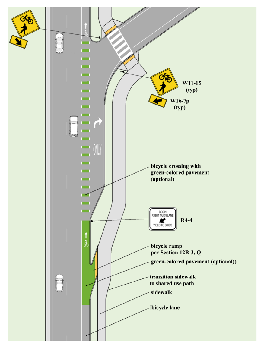
Source: Adapted from MnDOT Bicycle Facility Design Manual
Exit Ramps: Exit ramps can be difficult and unsafe for bicyclists to traverse due to the angle of the ramp and the often significant speed differential between bicyclists and motorists. Stop signs or signals are encouraged for motorists turning from the off ramp to the local route rather than allowing a free-flowing movement because this will increase the safety of the bicyclists. For ramp crossings where vehicle speeds are likely to be 30 mph or less at the crossing and ramp volumes result in regular gaps in traffic, it may be acceptable to provide on-street bicycle lanes. The potential conflict zone with turning motorists should be marked with dotted lines and green colored pavement at the crossing. Designs that permit high-speed free-flow movements from the exit ramp to an arterial roadway are not advised if regular bicycle and pedestrian activity is expected at the crossing locations. If prevailing vehicle speeds and volumes limit yielding behavior or adequate gaps in traffic, or where sight distance does not meet recommended criteria, it may be necessary to consider an active warning device or a traffic signal, as shown in Figure 12B-3.21.
Figure 12B-3.22: Exit Ramp with Bicycle Lane Crossing and Advance Warning or Traffic Signal
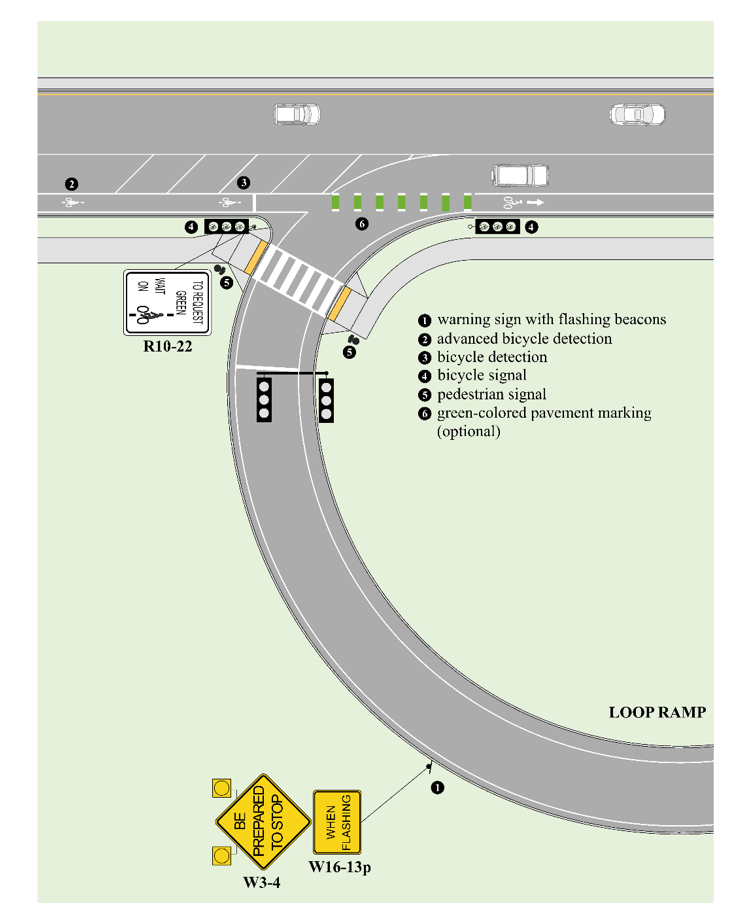
Source: Adapted from MnDOT Bicycle Facility Design Manual
At complex interchanges that have high volumes of bicyclists or pedestrians, high-speeds and free-flowing motor vehicle movements, a well signed and clearly directed grade-separated crossings may be necessary. These grade-separated facilities should still include good visibility, be convenient, and consist of adequate lighting. (AASHTO Bicycle Guide 4.12.9).
Two design guides provide detailed guidance on how to safely and accessibly provide safe facilities for people biking through interchanges:
- ITE Design Guidelines to Accommodate Pedestrians and Bicyclists at Interchanges, 2016, identifies specific dimensions, safety features, signage, pavement markings, design geometries, and other treatments.
- NCHRP Research Report 948: Guide for Pedestrian and Bicyclist Safety at Alternative and Other Intersections and Interchanges, 2021, provides specific guidance for other alternative interchange designs such as Diverging Diamond Interchange, Restricted Crossing U-Turn, Median U-Turn, and Displaced Left-Turn.
Q.Bicycles at Roundabouts
In designing roundabouts for bicycle usage, single lane roundabouts are safer and easier to navigate for bicyclists. Multi-lane roundabouts include too many conflict points due to bicyclists weaving/changing lanes and motorist cutting off bicyclists when exiting the roundabout.
In instances of bicycle lanes approaching a roundabout, the bicycle lane should be terminated at least 100 feet from the edge of the entry curve of the roundabout and prior to the crosswalk. Also, prior to the roundabout and after the termination of the bicycle lane, a tapering of the bicycle lane to the travel lane should be provided. This is done to achieve the appropriate entry width for the roundabout and the taper should be 7:1 for a 20 mph design speed or 40 feet for a 5 to 6 foot bicycle lane. Additionally, the bicycle lane line should be dotted 50 to 200 feet in advance of the taper to encourage bicyclists to merge into traffic. While some bicyclists may be comfortable traversing a roundabout in a shared lane environment, many bicyclists will not feel comfortable navigating roundabouts with vehicular traffic, especially multi-lane roundabouts, high-speed design roundabouts, and/or complex roundabouts. For comfort and safety reasons, roundabouts may be designed to facilitate bicycle travel on a shared use path.
Although the MUTCD directs on-street bicycle lanes to be terminated in advance of roundabouts, bicyclists should be given the option to merge with traffic and ride through the roundabout as a vehicle, or exit onto the adjacent sidewalk via a ramp. In many jurisdictions, bicyclists riding on sidewalks may be prohibited. However, the sidewalk can be widened and converted to a shared use path so it is lawful for bicyclists to traverse the roundabout separated from traffic. Bicycle ramps transition from the roadway to sidewalks prior to a roundabout and the following criteria should be followed:
- Place bicycle ramps at the end of the full width bicycle lane and just before the taper of the bicycle lane.
- Where no bicycle lane is present on the approach to the roundabout, a bicycle ramp should be placed at least 50 feet prior to the crosswalk at the roundabout to prevent pedestrians from mistaking the ramp as a crosswalk.
- Bicycle ramps should be placed at a 35 to 45 degree angle to the roadway.
- Bicycle ramps are intended for the exclusive use of bicyclists and therefore the slopes need not comply with pedestrian accessibility guidelines. Ramp grades can be steeper than pedestrian curb ramps; however, grades of 5 to 8% can help to address issues of comfort when transitioning from one elevation to another.
- Where a bicycle ramp connects directly into a sidewalk or shared use path, use a detectable warning surface at the top of the bicycle ramp and supplement with a directional indicator to guide pedestrians away from the bicycle ramp.
- The cross slope of a bicycle ramp should not be more than 2% to reduce the chance of bicyclists slipping on the bicycle ramp, especially during winter months.
If the ramp is placed within the sidewalk, it should be designed to meet accessibility requirements and include detectable warning surfaces at the bottom of the ramp instead of the top.
Bicycle ramps at the exits of roundabouts should be built with the similar geometry and placement as ramps at roundabout entries. Bicycle ramps at the exits of roundabouts should be placed at least 50 feet beyond the crosswalk of the roundabout. Refer to AASHTO Bicycle Guide 4.12.11 and the FHWA Roundabout Guide.
Back to topR. References
American Association of State Highway and Transportation Officials (AASHTO). A Policy on
Geometric Design of Highways and Streets (referred to as “Green Book”). Washington, DC. 2004.
American Association of State Highway and Transportation Officials (AASHTO). Guide for the Development of Bicycle Facilities. Fourth Edition. Washington, DC. 2012.
Federal Highway Administration (FHWA). Separated Bike Lane Planning and Design Guide. U.S. Department of Transportation, Washington, DC. 2015.
Institute of Transportation Engineers (ITE). Recommended Design Guidelines to Accommodate Pedestrians and Bicycles at Interchanges. Washington, DC. 2016.
National Association of City Transportation Officials, (NACTO). Urban Bikeway Design Guide. Second Edition. New York, New York. 2014.
National Association of City Transportation Officials, (NACTO). Don’t Give Up at the Intersection. New York, New York. 2019.
National Cooperative Highway (NCHRP) Research Report 641: Guidance for the Design and Application of Shoulder and Centerline Rumble Strips. Transportation Research Board, Washington, DC. 2016.
National Cooperative Highway (NCHRP) Research Report 766: Recommended Bicycle Lane Widths for Various Roadway Characteristics. Transportation Research Board, Washington, DC. 2014.
National Cooperative Highway (NCHRP) Research Report 926: Guidance to Improve Pedestrian and Bicycle Safety at Intersections. Transportation Research Board, Washington, DC. 2020.
National Cooperative Highway (NCHRP) Research Report 948: Guide for Pedestrian and Bicyclist Safety at Alternative and Other Intersections and Interchanges. Transportation Research Board, Washington, DC. 2021.
Ohio Department of Transportation (Ohio DOT). Multimodal Design Guide. Columbus, Ohio. 2022.
Back to top