Content Information
On this page...
Geopak Survey Menu
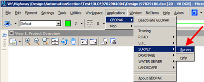
Start GEOPAK from the MicroStation menu by selecting Applications > GEOPAK > Activate GEOPAK, as shown at the right.

After GEOPAK has been activated, access the GEOPAK Survey menu from the MicroStation menu by selecting Applications > GEOPAK > SURVEY > Survey, as shown at the right.
The Survey tool bar should display, as shown at the right.

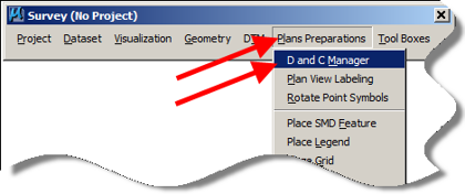
- From the Survey tool bar, click “Plans Preparations > D and C Manager”), as shown below, to open the Design and Computation (D&C) Manager dialog box, (here-in-after referred to as D&C). The D&C tools will be used to plot the horizontal alignment chains. These chains are different from survey chains in that they may contain spirals, curves, etc.
- Confirm that the correct D&C “.ddb” file is open. The path to the “.ddb” file is as follows:
W:\Highway\Design\CADD\Geopak\Survey\SeedFiles\GEOPAKSurvey\DCManager\IDOTSurvey.ddb
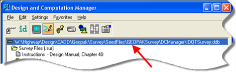
The “.ddb” file path should display in the first line of the D&C Manager dialog, as shown below.
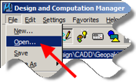
If the wrong “.ddb” file is attached, find and attach the correct one by clicking File > Open, as shown at the right.
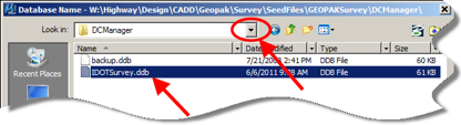
The File > Open command will open the “Database Name” dialog. Click the drop-down list arrow, as shown at the right, to locate and select the correct file. Double-Click the file name to open it.
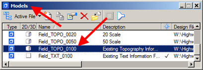
- The horizontal alignment is drawn in the Field_TOPO_0100 model.
Open the Field_TOPO_0100 model by double-clicking the model name in the Models dialog, as shown at the right.
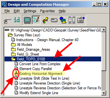
- In D&C, double-click on the Field_TOPO_0100 folder and then double-click on the Existing Horizontal Alignment tool. This tool stands out because it is the only tool in this folder with a paint brush icon in front of it, as shown at the right.
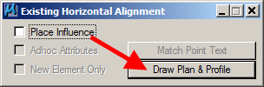
- The above step should cause the Existing Horizontal Alignment dialog to display, as shown at the right. To continue to the next step, click the Draw Plan & Profile button, which should open the Draw Plan & Profile dialog, as shown below.
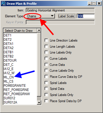
- In the Draw Plan & Profile dialog, make sure that the Element Type is set to Chains, as shown by the red arrow at the right. Next, select (single-click) the alignment that you would like to draw, as shown by the blue arrow. Clicking on the alignment name draws that alignment into the MicroStation file. Multiple alignments can be drawn by clicking on each chain name individually.
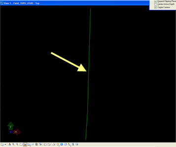
- The alignment should look something like what is shown at the right. The line representing the alignment is all that is drawn in this model.
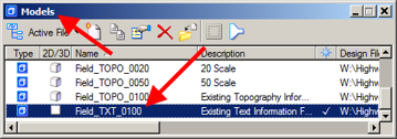
- The horizontal alignment curve information, stationing, and tick marks are all drawn into the Field_TXT_0100 model. Open this model, as shown at the right.
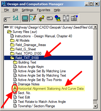
- In D&C, double-click on the Field_TXT_0100 folder and then double-click on the Horizontal Alignment Stationing and Curve Data tool. You can easily recognize this tool as it is the only one with a paint brush icon in front of it in this folder.
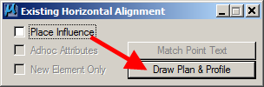
- The above step should cause the Existing Horizontal Alignment dialog to display, as shown at the right. To continue to the next step, click the Draw Plan & Profile button, which should open the Draw Plan & Profile dialog, as shown below.
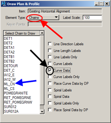
- The first thing to be drawn is the curve data. Make sure that the Element Type is set to Chains, as shown by the red arrow. Place a check (R) on the Curve Data item, as shown by the black arrow. Single-click on the alignment name (blue arrow). This will cause the curve data for that chain to be drawn into the MicroStation file.
Repeat for as many alignments as necessary.
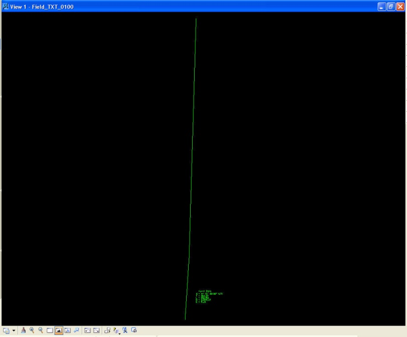
- The curve data should look similar to this.
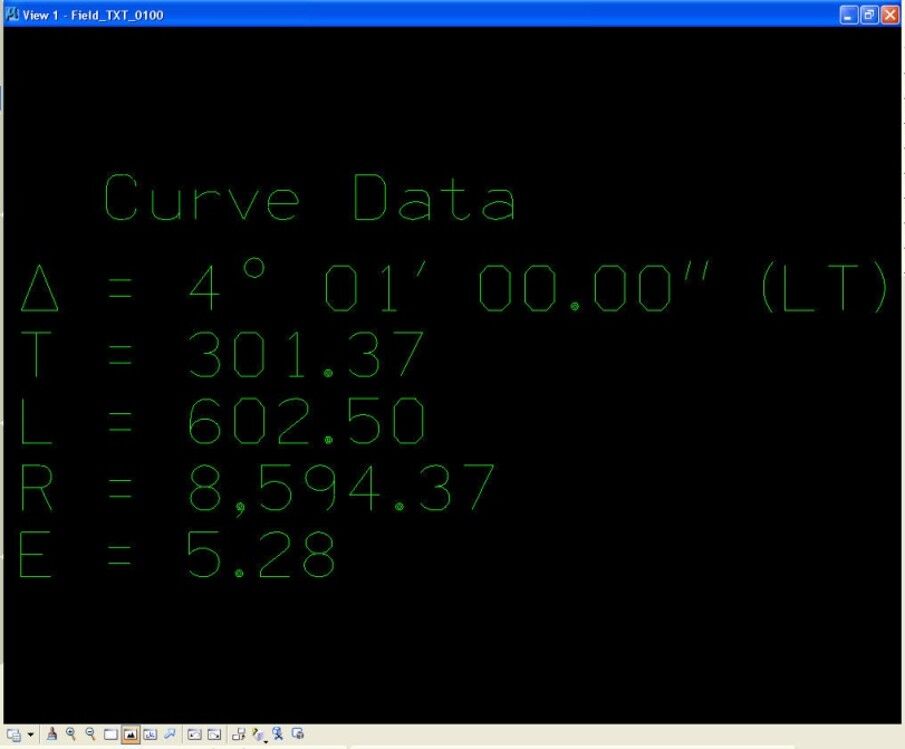
- To draw the curve data into this model the line representing the alignment must also be drawn into the file.
Note:
This line is not needed in the Field_TXT_0100 model and should be deleted.
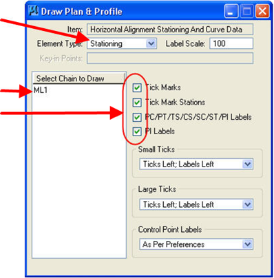
- To draw the tick marks and stationing, change the Element Type to Stationing, as shown at the right. Place check-marks (R) in front of the items to be drawn. When ready to draw, single-click on the appropriate alignment name and the selected information will be drawn into the file.
Repeat for as many chains as necessary by single-clicking on each individual alignment name.
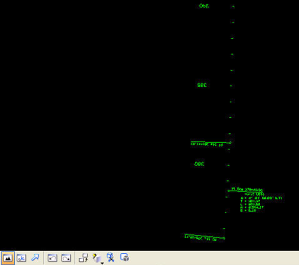
- The stationing and tick marks should now be drawn into the MicroStation file and should resemble the data shown below.