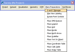
The Design and Computation (D&C) Manager in GEOPAK is used to draw elements in MicroStation models that are not collected in the field and drawn using the Visualization tool within GEOPAK Survey. To open the D&C Manager from the GEOPAK Survey menu bar, selectPlan Preparations > D and C Manager, as shown at the right. This will open two new dialog boxes. The paths shown in this manual are for internal IDOT employees only.
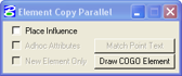
The first and the smaller of the two D&C Manager dialog boxes is shown at the right. This box is only used when drawing horizontal alignments. Make sure that the Place Influence check-box is not checked, (£).
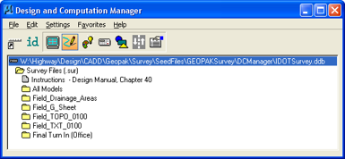
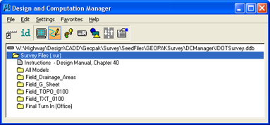
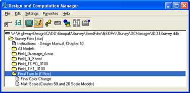
The second dialog to display is the main D&C Manager dialog box. The “.ddb” file path shown in the top line of the dialog data area should be as follows, and as shown below:
Items will be selected from this dialog to be drawn in the MicroStation model.
If the correct “.ddb” file is not attached (displayed), correct this in steps 4 and 5.
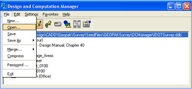
If the correct “.ddb” file is not attached, select File > Open, as shown at the right.
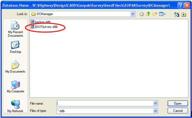
Then browse to the …DCManager directory listed above and select the IDOTSurvey.ddb file, as shown.
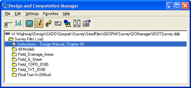
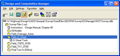
The first folder listed in the D&C Manager contains instructions and commands for the “.sur” file, as shown at the right. This is also the file that should be open at this time.
The first option under the Survey Files (.sur) folder is for the Instructions file. Double-clicking on the Instructions option will open the internet version of the Design Manual. Browse to Chapter 40 for the Survey instructions.
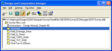
Within the “.sur” folder are subfolders that contain the tools that are needed to complete each individual model. The All Models folder contains tools that could be used in all of the models.
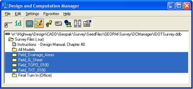
The folders selected at the right, (highlighted), represent the models in the “.sur” file that need to have information added to them. Each of these folders contains only the tools needed for the model with the same name.
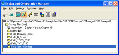
The “Final Turn In (Office)” folder contains two tools that will be run on the “.sur” file before it is released to the design section.
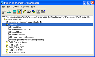
The All Models folder contains tools that could be used in any of the models.
Element Copy – Starts the MicroStation tool that allows you to copy objects in the model.
Element Match Attribute – Starts the MicroStation command that will match the element attributes of one item, (including level, color, weight and style), so that when you create another item it will look the same.
Element Move –Starts the MicroStation tool that allows you to move an object within the model.
Element Selection – This tool is used to select and deselect elements for modification or manipulation. The elements will “highlight” when selected. Click on the element to “select” it, click off the element (in an unused area of the file) to “deselect” it.
Measure Horizontal Distance – The “.sur“ file is a 3D file so the measurements obtained with the standard MicroStation measurement tool may not be what you want. Using the Measure Horizontal Distance macro will provide the horizontal distance between the two selected points and will not be affected by any possible elevation differences.
Open Explorer to current working directory – This tool activates a session of Windows Explorer that is automatically opened to the folder containing the active MicroStation file.
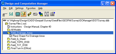
The Field_Drainage_Areas folder contains a tool used to manually draw drainage area shapes into the model.
The Field_G_Sheet folder contains the tools required to complete the “G” sheet references.
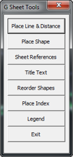
Double-clicking on the “G Sheet Tools” command opens a tool menu, as shown at the right, with everything necessary to complete the “G sheet” model. Detailed instructions for the creation of “G sheets” can be found in Design Manual section 1F-8.
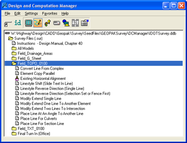
The Field_TOPO_0100 folder contains all of the tools necessary to complete this model, as listed below.
Convert Lines From Complex – Some editing tools in MicroStation, (such as the “Modify” tools in this folder), do not work with some element types. This “Convert…” tool is used to “drop the complex element status” to “simple” elements that can be altered with the Modify element commands.
Element Copy Parallel –This tool is used to copy an element a specified distance parallel to itself. It is used to create pipe width, from a single center-line copied parallel left and right.
Existing Horizontal Alignment – Double-clicking on this menu item allows you to draw horizontal alignments into the TOPO model. Detailed horizontal alignment instructions can be found in Design Manual section 40D-13.
Linestyle Shift (Slide Text In Line) – This tool slides the graphic element portions of custom linestyles, (such as text, arrows, etc.), so that they appear where you want them to display along the linestyle element.
Linestyle Reverse Direction (Single Line) – This tool changes the direction of the graphic element portions of custom linestyles, (such as text, arrows, etc.), so that text elements are not upside down and arrows point in the correct direction.
Linestyle Reverse Direction (Selection Set or Fence First) – Using the Element Selection tool or the Fence tool along with this “…Reverse Direction”tool, change the direction of the graphic element portions of several custom linestyles with a one step process.
Modify Extend Single Line –Used to shorten or lengthen a line element.
Modify Extend One Line To Another Element –Extends or cuts one line where it intersects another line.
Modify Extend Two Lines To Intersection –Extends or cuts two lines at the intersection of the lines.
Place Line At An Active Angle To Another Line – This tool draws a line at a specified angle and length from another line. This can be used to draw aprons at a 90 degree angle from the centerline of the pipe, for one half the width of the apron.
Place Line For Culverts – This tool is used to draw culvert lines with the correct attributes (level, color, weight and style).
Place Line For Section Line - This tool is used to draw section lines with the correct attributes (level, color, weight and style).
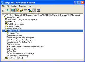
The Field_TXT_0100 folder contains all of the tools necessary for completing the TXT model.
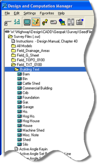
Building Text – This folder contains all of the necessary identification text for any buildings or structures on a project, as shown at the right. Double-clicking on any of the Building Text options attaches the specific text to the cursor, making it ready for placement in the file.
Active Angle Keyin – Allows manual keyboard entry of an “active angle” for text placement.
Active Angle Set By Matching Line – The “active angle” can be set by clicking to an existing line element. The line must consist of only two points.
Active Angle Set By Matching Text – The “active angle” can be set by clicking on and matching the angle of an existing text element.
Active Angle Set By Two Points – The “active angle” can be set by placing two points in the file. Any two data-points in the file will set the active angle, with or without an existing element.
Drainage Notes – This command will display a dialog box, allowing the input of “type and size” of drainage structures to be labeled.
Horizontal Alignment Stationing And Curve Data – This tool sets the appropriate element attributes, (such as weight, color, level, and size), for Horizontal Alignment stationing, tick marks, curve data and alignment point labels. Double-click on this item to start it. Detailed instructions for horizontal alignments can be found in Design Manual section 40D-13.
Sect. No. – This tool is used to place the text “Sect. No.” where multiple sections meet. If the Township and Range are the same for each Section, it is only necessary to place the full Township/Section/Range note one time. This tool would be used for the other sections.
Text Edit – This activates the Text Editing tool for altering existing text.
Text Rotate to Match Active Angle – Rotates text to match the currently set active angle.
Township/Section/Range – This tool places the Township, Section and Range information.
The Final Turn In folder contains the last two tools used on the file contents prior to giving the file to a design section. Each tool also contains brief instructions on proper use. These tools will be used only by the Ames office personnel.
Final Color Change – This tool will change the color of all items in the model to the approved color. This tool should only be used on the Field_TOPO_0100 and Field_TXT_0100 models.
Multi Scale (Creates 50 and 20 scale Models) – This tool creates a 50 scale copy and a 20 scale copy of the …TOPO_0100 model, and appropriately scales the contents of the model to match the model name; …TOPO_0050 and TOPO_0020. These models are to be used for creating 50 and 20 scale plan sheets. This tool should only be used on the Field_TOPO_0100 model.