Content Information
On this page...
Geopak Survey Menu
Start GEOPAK from the MicroStation menu by selecting Applications > GEOPAK > Activate GEOPAK, as shown at the right.

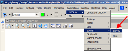
After GEOPAK has been activated, access the GEOPAK Survey menu from the MicroStation menu by selecting Applications > GEOPAK > SURVEY > Survey, as shown at the right.
The Survey tool bar should display, as shown at the right.

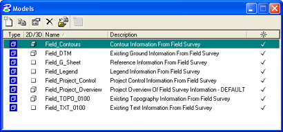
- Open the MicroStation Models dialog, as shown at the right, and Double-click on Field_Contours model name to open it.
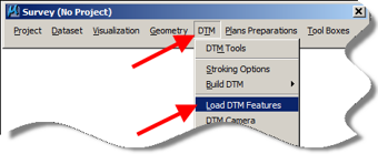
- Select DTM > Load DTM Features on the Survey tool bar, as shown at the right. This will open the Load DTM Features dialog box, as shown below. This dialog will be used to draw the contours.
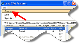
- On the Load DTM Features dialog box, select File > Open. This will open the Open Preferences File dialog, as shown below.
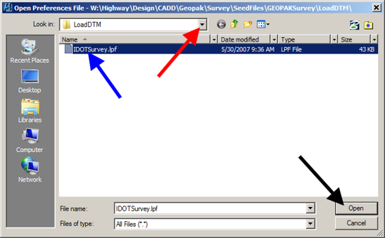
- On the Open Preferences File dialog, use the drop-down list arrow, as shown by the red arrow below, and navigate to the following folder:
W:\Highway\Design\CADD\Geopak\Survey\SeedFiles\GEOPAKSurvey\LoadDTM\
The IDOTSurvey.lpf file should be at this location, blue arrow. This file sets all of the correct attributes for items to be drawn.
Double-click the IDOTSurvey.lpf file to open it, or select (highlight) the file name and click the OK button, shown by the black arrow.
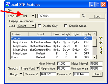
- Make sure that the Load File option is set to TIN, as shown at the right.
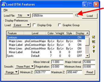
- Check that the correct TIN file has been selected. If not, click the Magnifying Glass browse button (), as shown at the right. Navigate to the correct location and select the correct file.
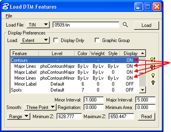
- The Contours feature and the three features directly below Contours, located by the arrows at the right, should have the Display attribute toggled ON. The Display attribute for all other Features should be OFF, including the Minor Label under Contours, which is not used. To toggle the ON/OFF Display attribute for a feature, select (highlight) the desired Feature row and Click the correct On or OFF “light bulb” (or) icon.
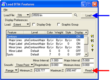
- You must click the Read button, shown by the red arrow, so that GEOPAK can figure the Minimum Z and Maximum Z.
Click the Load button, shown by the blue arrow, to draw the contours into the file.
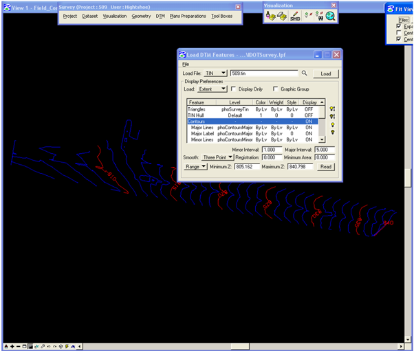
- The Field_Contours model should now contain contours similar to the picture below.