Content Information
On this page...
Start GEOPAK from the MicroStation menu by selecting Applications > GEOPAK > Activate GEOPAK, as shown at the right.

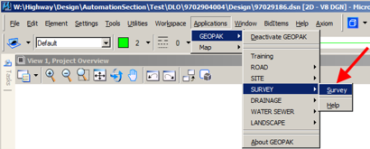
After GEOPAK has been activated, access the GEOPAK Survey menu from the MicroStation menu by selecting Applications > GEOPAK > SURVEY > Survey, as shown at the right.
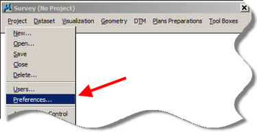
From the GEOPAK Survey menu tool bar, select Projects > Preferences.
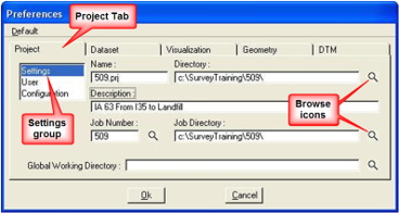
Complete the Project > Settings based on the Survey And Photogrammetry Number (SAP#); e.g. 509 in this example. Use the Browse icons to locate the appropriate Directories (folders).
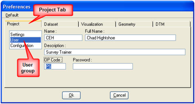
Fill in the Project > User information based on the party chief.
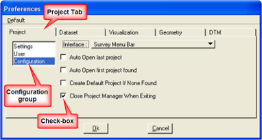
For the Project > Configuration information, the check-box for “Close Project Manager When Exiting” can be checked (R), as shown at the right.
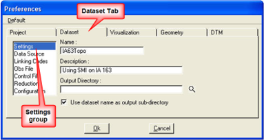
The Dataset > Settings preferences: The data entered here will be used as the defaults for the dataset names and descriptions that will be created later in the process.
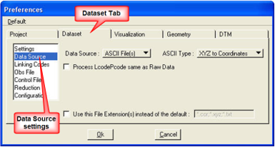
The Dataset > Data Source information sets the type of file the dataset will use.
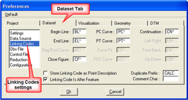
Dataset > Linking Codes will not be used. Therefore, the settings in this dialog do not matter.
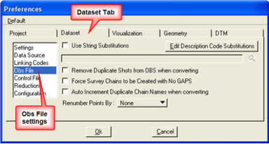
The default Dataset > Obs File settings should be used as shown.
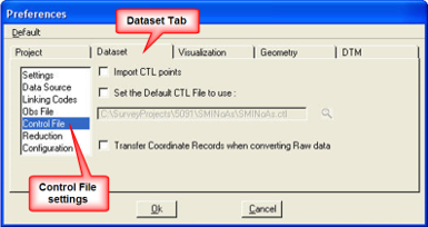
Use the default Dataset > Control File settings, as shown.
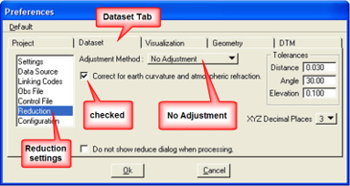
In the Dataset > Reduction preference settings dialog, the Adjustment Method should be set to No Adjustment, and the “Correct for earth curvature …” check-box should be checked (R).
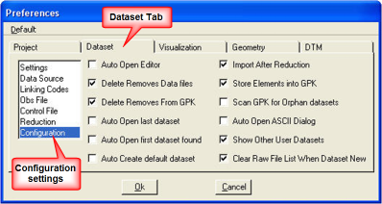
The Dataset > Configurationcheck-boxes values determine how the Dataset operations run.
The Visualization > Settings determines what “SMD Feature File” to use and what Plot Scale is to be used to draw the objects.
Use the Plot Scale of 5, and an SMD File location as shown below. Use the browse button () to locate the SMD file location.
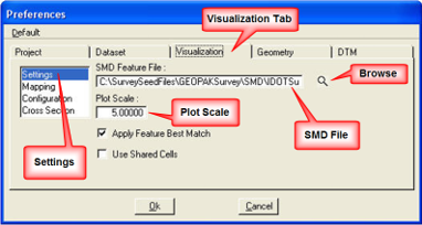
C:\SurveySeedFiles\GEOPAKSurvey\SMD\IDOTSurvey.smd
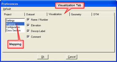
All settings check-boxes should be checked (R) on the Visualization > Mapping Preferences dialog. This will give you the ability to plot these items in MicroStation.
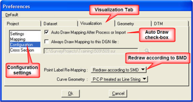
For the Visualization > Configuration preference settings, the “Auto Draw …” check-box should be checked (R), which will cause the survey information to automatically draw after processing.
The Point Label Re-Mapping should be set to Redraw according to SMD.
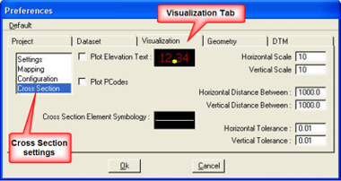
Use the default values for the Visualization > Cross Section preference settings.
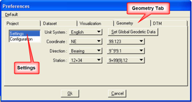
Use the values as shown at the right for the Geometry > Settings preferences for an English project,
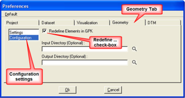
For the Geometry > Configuration settings, the “Redefine Elements in GPK” check-box should be checked (R). This will allow for the editing of information after it has already been processed.
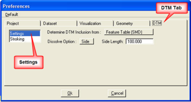
The DTM > Settings preferences should be set as shown at the right. These settings determine how the “tin” file is created.
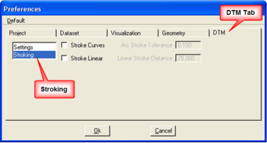
Use the default settings for the DTM > Stroking preferences, as shown at the right.
Now that the Preferences have been set you can create the GEOPAK Survey project.
From the GEOPAK Survey menu tool bar, select Project > New.
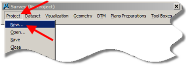
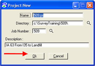
The Project New dialog will appear. It should contain the correct information from the Preferences that have been set.
When the values are correct, click the OK button.