Content Information
On this page...
The GEOPAK Edit Crossing Chains tool can be used to find crossing breaklines in the Field_DTM model. The Edit Crossing Chains dialog is accessed through Geopak Menus.
Start GEOPAK from the MicroStation menu by selecting Applications > GEOPAK > Activate GEOPAK, as shown at the right.

After GEOPAK has been activated, access the GEOPAK Survey menu from the MicroStation menu by selecting Applications > GEOPAK > SURVEY > Survey, as shown at the right.
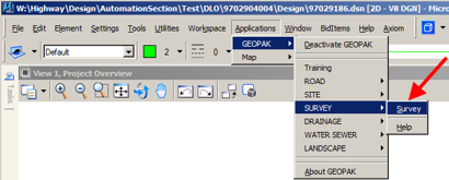
The Survey menu should display, as shown below.
From the Survey menu tool bar, select Geometry > Chains > Crossing Chains, as shown at the right.
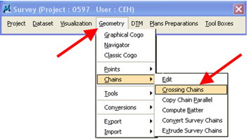
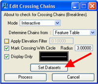
The Edit Crossing Chains dialog will open, as shown at the right.
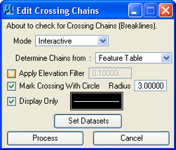
The descriptions of the options on the Edit Crossing Chains dialog are as follows:
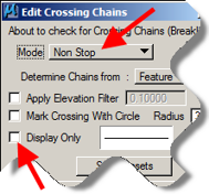
Mode - There are two different Modes; Interactive and Non-stop, as shown at the right.
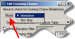
Non Stop - This option finds all of the crossing breaklines and marks them with a circle. You can then go through the model and find and fix the crossing breaklines.
Interactive - This option searches for all of the breaklines and allows you to continue using the tool to help find each crossing breakline. This tool allows you move from one error to another and it fits each error to the MicroStation View.
Determine Chains from – There are three options available, but the one we use is Feature Table.
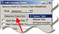
Feature Table –
This option causes the Edit Crossing Chains tool to check all the survey chains that the “smd” file has determined to be good for the DTM.
There are three check-box (R) options on the left side of the Edit Crossing chains dialog.
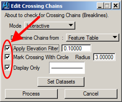
Apply Elevation Filter – If checked (R), this option will cause the tool to skip crossing breaklines where the elevations are within an acceptable tolerance.
Mark Crossing With Circle – Checking this option (R) causes the tool to place an “error circle” at the crossing error location. The circle radius can be set, as shown at the right.
Display Only – If the Interactive Mode is being used, the Display Only option should be checked (R) so that the “error circle” goes away after the correction has been made.
If the Non-stop Mode is being used, the Display Only option should be unchecked (£), which will cause the “error circles” to be drawn permanently into the file so the errors can be found after the tool stops running.
The attributes of the Crossing Chain circle, that is drawn as described above, can be changed in the Edit Crossing Chains dialog by clicking on the line in the box next to the Display Only text, as shown at the near right. This will cause the Set Feature dialog to display.
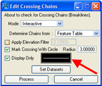
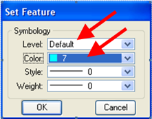
On the Set Feature dialog, shown at the far right, change the Level to one that is not used by anything else. Also change the Color to one that has not been used before. Click the OK button when finished.
The Set Search dialog allows you to choose which survey information is to be checked, (R), as shown at the far right.
To open the Set Search dialog, click the Set Datasets button, on the Edit Crossing Chains dialog, as shown at the near right.
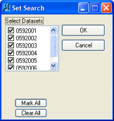
Click the OK button on the Set Search dialog when finished making selections.
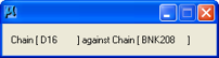
When all information on the Edit Crossing Chains dialog is correct, click the Process button, shown above. The dialog at the right will appear while GEOPAK checks all of the appropriate chains to determine if any of them cross.
If the Non-stop Mode was selected and the Display Only option was unchecked (£), as shown at the right, the tool places circles at all of the crossing locations and the tool will then disappear. MicroStation View Tools must now be used to find and display each error. The GEOPAK Edit Point or Edit Chain tools should then be used to fix the error.
If you have chosen the Interactive Mode (above), another variation of the Edit Crossing Chains dialog will appear, as shown at the right. The first Chain Crossing error will be automatically displayed with the MicroStation Fit View tool. The crossing will be located by a circle as shown below, which is drawn with the attributes that had been set previously. The tool will cause the graphic display of the two crossing chains to highlight, as shown below.
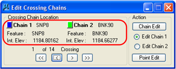
The highlight colors of these chains are set by clicking on the “color picker” icon and selecting a color, as shown in the red rectangle above, right. The dialog will also provide the names of the two crossing chains, and the feature code and elevation of each chain where they cross. You can use the “back and forward” buttons (), at the bottom of the dialog, to move from one error to another. The dialog also shows how many crossing errors are within the datasets you have selected. You can then toggle which chain you want to work with and whether you want to edit a point or the chain, as shown on the right side of the dialog, above.
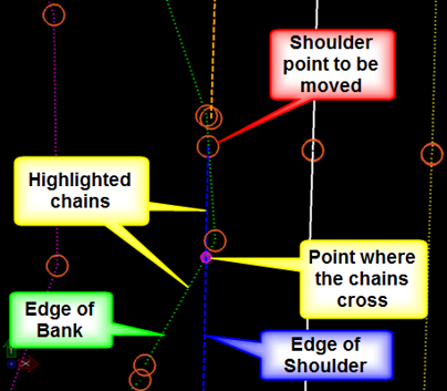
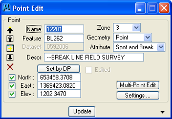
In the graphic example above, the green Edge of Bank line crosses the blue Edge of Shoulder line. For this example the last point of the Edge of Shoulder breakline will be moved so the Shoulder chain will not cross the Edge of Bank line. When selections have been made, click the Point Edit button. This will cause the Point Edit dialog to display, as shown below.
The point number to be edited must be entered into the Point Edit dialog or the point must be selected graphically, using the Set by DP button, which will then populate the dialog. In this example the “Northing” of the last point on the Edge of Shoulder survey chain will be changed. When the point has been changed, click the Update button.
If the error has been corrected and the chains no longer cross, the program will automatically move on to the next error point and you will not automatically see the corrected view that is shown at the right.
The MicroStation View Previous tool can be used to move back to this “corrected” view if you want to verify that the correction was made.
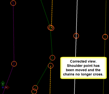
Since one error was just corrected, the number of errors shown in the dialog will now be reduced by one.
The next graphic example, at the right, shows another error. The Draw chain doubles-back on itself.
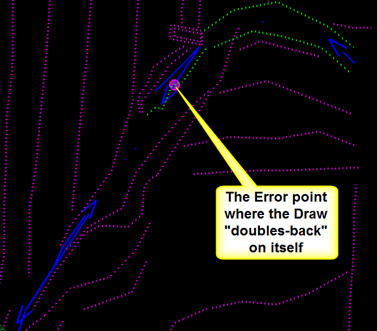
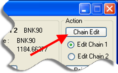
To fix this error, use the Chain Edit button on the Edit Crossing Chains dialog. Click on the toggle to determine which chain to edit. Then click the Chain Edit button.
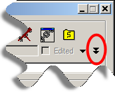
The Chain Edit dialog will appear. If you chose the correct chain to edit, it will already be selected in this dialog. If the dialog does not show all of the information that is shown here, click the black double-down arrows in the lower right hand corner of the Chain Edit dialog, (as shown below).
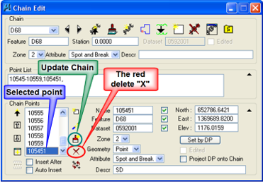
The point to be removed has been selected (highlighted) in the example at the upper right. After the point has been selected, click the red delete “X” icon to remove it. You can also edit the point number in the Point List area. To update the chain with your corrections, click the Update Chain button (the paint brush icon).
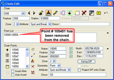
The Error Point # 105451 has now been removed from the corrected and updated chain, as shown at the right in the Point List.
The area containing the corrected survey chain is graphically shown at the right and the Error Point has been removed.
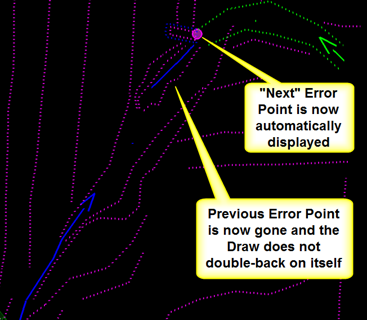
The tool has automatically moved on to the next error and is displaying a new circle at that location.