Content Information
On this page...
Within GEOPAK Survey there is an easy way to create a TIN file. This process compares the survey information stored in the GPK file with the information in the SMD file to determine if the data is good for ground processing. This is the perfect process to use when it is necessary to create a TIN file for the purpose of reviewing the field data for busts.
One problem with this process is that there is no choice in what data is included in the TIN file. This process can create triangles that do not truly represent the existing ground. Customers who use this data may possibly assume that the existing ground in these areas is accurate, just because the data is part of the TIN. Some examples of where this could occur are as follows:
- Where draws are surveyed far outside of the rest of the field shots.
- Where the centerline of the roadway is shot for the additional 300’ past the survey limits.
- A point was edited and the Zone was not changed. GEOPAK will still consider this as good as ground.
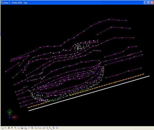
The field data used for this example is shown at the right.
Geopak Survey Menu
Start GEOPAK from the MicroStation menu by selecting Applications > GEOPAK > Activate GEOPAK, as shown at the right.

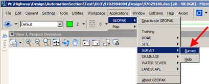
After GEOPAK has been activated, access the GEOPAK Survey menu from the MicroStation menu by selecting Applications > GEOPAK > SURVEY > Survey, as shown at the right.
The Survey tool bar should display, as shown at the right.

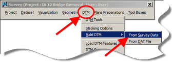
- On the Survey tool bar, select
DTM > Build DTM > From Survey Data, as shown at the right.
- This will open the Build DTM dialog box.
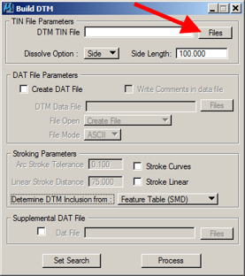
Click the Files button to name the TIN file.
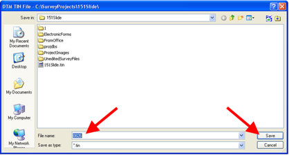
- Confirm that the correct directory is selected then name your file to match the SAP number for the project.
Click the Save button.
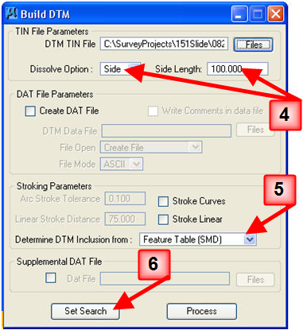
- The Dissolve Option should be set to the Side option, and the Side Length is to be set to 100. This will limit the side length of the TIN file triangle creation to be no longer than 100’.
- The “Determine DTM Inclusion from” option should be set to “Feature Table (SMD)”. The SMD file contains the information that determines which feature codes are good for ground shots.
- Click the Set Search button to select the data sets that should be included in the TIN file.
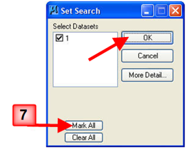
- Individual data sets to be included within the TIN can be selected by placing a check (R) next to each name. All of the data sets will usually be included in the TIN. To select all data sets, click the Mark All button.
Click the OK button after all selections have been made.
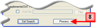
- When everything is set, click the Process button on the Build DTM dialog to create the TIN file.
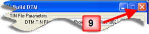
- The TIN creation process is complete after the text stops flashing in the MicroStation task bar at the bottom of the window. To close the Build DTM dialog, click the "X" in the red box at the upper right corner.
10. The TIN that was just created will not be drawn into the file automatically.
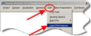
The first step to cause the TIN triangles to be drawn into the file is to select DTM > Load DTM Features on the Survey tool bar.
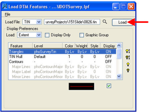
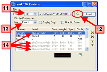
- This opens the “Load DTM Features” dialog box. The Load File option should be set to “TIN”.
- The name of the TIN file just created should automatically be shown in the TIN data entry field at the top of the dialog. If what is shown is not correct, click the magnifying glass Browse icon () and locate and select the correct TIN file.
- The Load option should be set to Extent. This will cause the complete TIN to be drawn into the model.
- If the dialog box does not display the same levels as shown at the right, the correct settings must be loaded so that everything will be drawn correctly.
If the settings must be changed, (as indicated above), click File > Open to choose the settings file, as shown at the right. This will open the “Open Preferences File” dialog, as shown below.
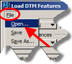
- Browse to the directory listed below,
W:\Highway\Design\CADD\Geopak\Survey\SeedFiles\GEOPAKSurvey\LoadDTM\
Select the IDOTSurvey.lpf file and then click the Open button, as shown below.
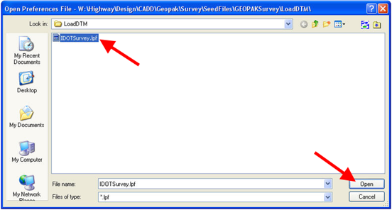
- To draw the Triangles into the model, highlight the Triangles row and click the light bulb icon (). It should now say ON in the Display column of the Triangles row.
As a second method for toggling the value in the Display column, you can double-click on the Triangles row to change the Display value to ON.
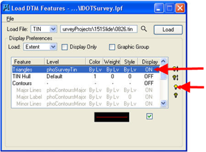
- When all of the settings are correct, click the Load button, as shown at the right. The TIN triangles should now be drawn into the MicroStation file model on the phoSurveyTin level.