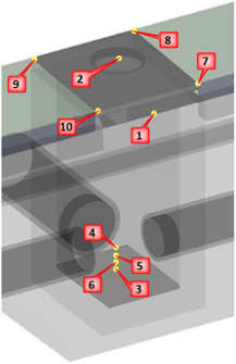
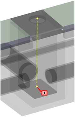
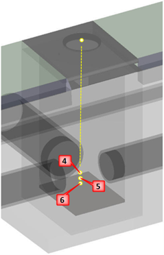
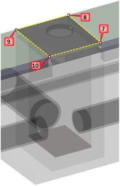
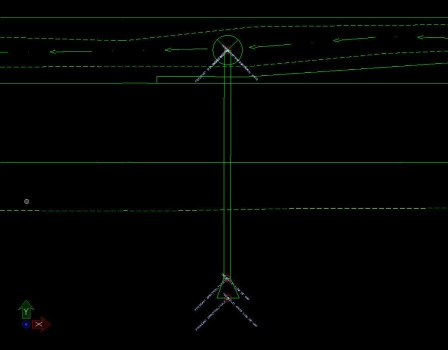
All storm sewer intakes must have enough shots to record the important information. All the necessary shots are shown in the example at the right. As you know, some MH’s are inaccessible for various reasons. Please note these as inaccessible and move on.
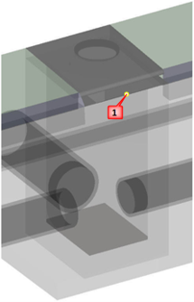
The first shot, with a feature code of IN, determines the location of the intake. A cell representing the intake will be drawn at this location in the MicroStation file. The description for this point should contain the BASIN SIZE, COVER SIZE, CONDITION (including amount of silt), LENGTH OF OPENING and DRAINAGE AREA.
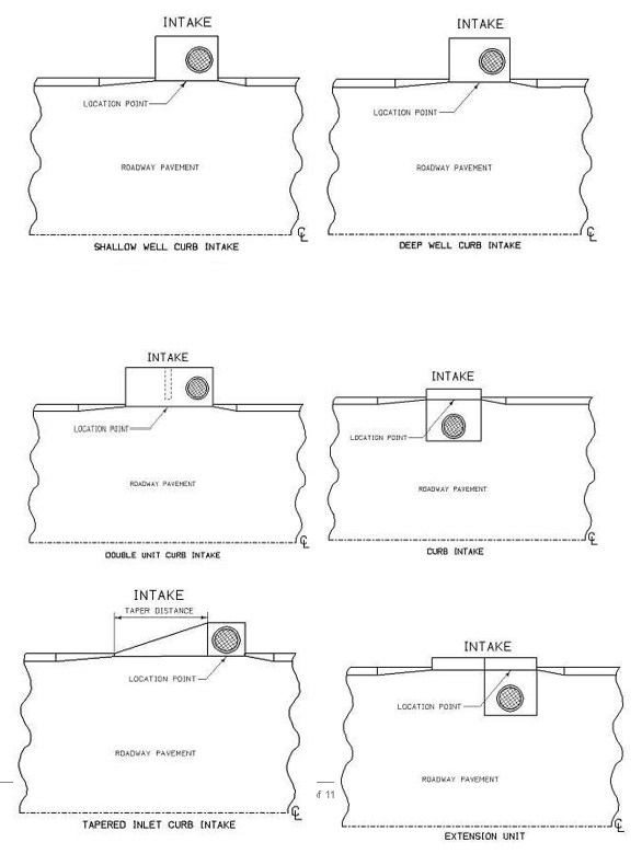
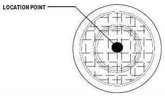
The location of the IN should follow these examples.
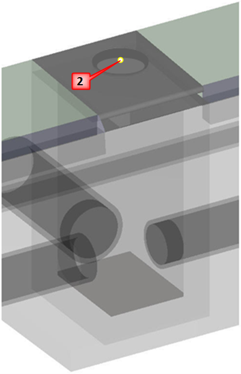
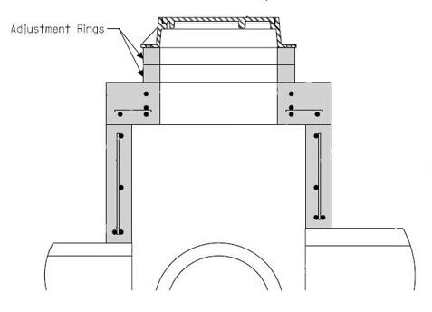
Shot number 2 is taken on the center of the manhole cover, if present. This shot should have the feature code of UE (Utility Elevation) and the description should be the size of the lid (26” MANHOLE). The UE feature is used instead of MH (Manhole) because the drawing becomes too cluttered in MicroStation if the intake and manhole cell are both drawn.
It is important for the designers to know if the MH has lift rings inside that total more than 16”. It is required to identify how many lifts there are and the thickness of each lift. This information should be placed in the UE for the manhole lid description. A photo of the inside of the manhole that shows the lift(s) while holding a ruler vertically against it would also be beneficial.
Point 3 is the bottom of the well shot and should have feature code UE. This shot should be at the same XY location as the point 2, the center of the manhole cover. The description for this point should be BOTTOM OF BASIN.
Points 4-6 in this example are for the flowlines of the pipes entering the intake. These points are stored with a feature code of STA-STE, depending on the utility owner. These points have the same XY location as the center of manhole shot. The description of these points should include the pipe diameter and flow direction (24” FROM NW).
If one of the pipes in the intake drains water out of the storm sewer system, see Step 8, below.
A survey chain of the top of the intake should also be shot with the feature of CON (Concrete Slab). The point description should be TOP OF INTAKE.
If one of the pipes connected to an intake drains water out of the storm sewer system, it should be treated as a normal pipe culvert. Surveying this pipe is the same as any other drainage culvert. The only difference when the pipe is connected to an intake is the duplication of the intake flowline shot. This PIP shot should be duplicated as a STA-STE (depending on utility owner) and the description for the shot should begin with the same identifier as the rest of the shots for the intake. A pink sheet (Form 621001-E) does not need to be created for this pipe.
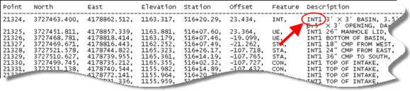
The first item entered in the description field for each intake shot intake is an identifier, as shown below. The easiest way to name the intake identifiers is to start with the name of INT1 for first intake surveyed. The identifier number for each intake surveyed thereafter will sequentially increase, e.g., INT2, INT3, INT4. This identifier will be used by the customer to group all shots together that are associated with each drainage structure.
The feature code INB should be used when surveying bee hive intakes. The location of the INB shot should be at the center of the intake and at the surface flow elevation. With the exception of the IN feature, all other shots required shots are the same as for a standard intake.
Manholes that are not related to an intake should be shot with the feature MH. All other features related to the manhole should be collected in the same manner as for the standard intake.