Content Information
On this page...
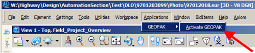
- Activate GEOPAK by selecting Applications > GEOPAK > Activate GEOPAK from the main MicroStation toolbar, as shown below.
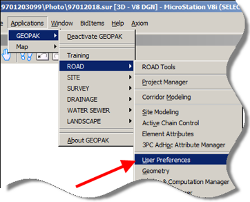
- You must tell GEOPAK where the “.gpk” file containing the station and offset information is located. This is done by changing the user preferences. From the main MicroStation tool bar, select
Applications >
GEOPAK >
Road >
User Preferences
as shown below.
- On the User Preferences dialog box click the COGO Preferences button.
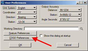
This will display the COGO Preferences dialog, as shown below.
- To locate the Job (GPK) Directory, click the magnifying glass browse icon (), as shown below.
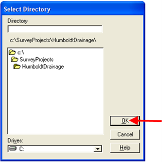
This will open either the Select Directory dialog, as shown below, or possibly the Browse for Folder dialog, which performs the same function.
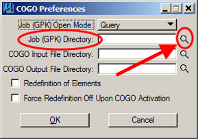
- Select the directory where the “gpk” file is located, then click the OK button, as shown below.
If you are using GEOPAK Project Manager, this should be set up within your project preferences. If you are not using Project Manager, but your “gpk” file is located in the same directory as the MicroStation file that you have open, you can leave the directory path blank and GEOPAK will list all of the “gpk” files in the directory that contains the open file.
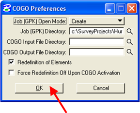
The action listed above should open the COGO Preferences dialog, as shown below.
- In the COGO Preferences dialog, click the OK button to approve the selected GPK Directory.
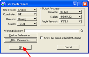
This should cause the program to return to the User Preference dialog, as shown below.
This should cause the program to return to the User Preference dialog, as shown below.
- To move on, click the OK button on the User Preferences dialog, as shown below.
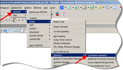
- From the main MicroStation tool bar, (as shown below), select:
Applications >
GEOPAK >
ROAD >
Geometry >
Coordinate Geometry
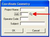
This should display the initial Coordinate Geometry dialog, as shown below.
The initial Coordinate Geometry (COGO) dialog box that appears allows the selection of the “.gpk” file that contains all of the survey information for the project. To see a list of available “gpk” files, click on the magnifying glass browse icon (), as shown below.
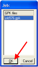
This will display the Job: dialog shown below.
In the Job: dialog, select (highlight) the correct “gpk” file and click the OK button.
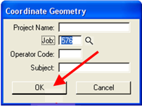
- When the correct Job displays in the Coordinate Geometry dialog, click the OK button to continue.
- On the second (and larger) Coordinate Geometry dialog box, shown below, select the following command:
File > Export > ASCII Points
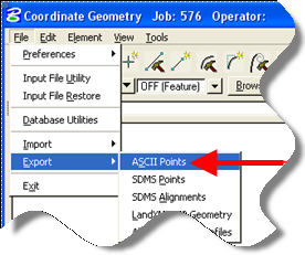
This should display the “Export GPK Points …” dialog, as shown below.
- The Export GPK Points to ASCII Coordinate File dialog is where the actual station offset report is created. Use the drop-down list arrow, (located at the upper right corner of the dialog), to select the File Create option.
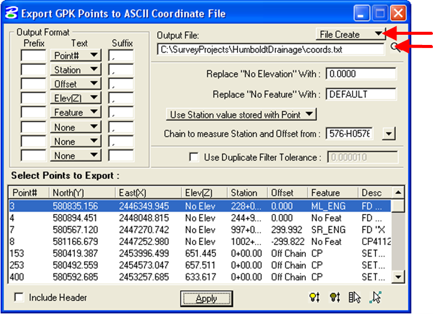
Next, click on the magnifying glass browse icon (). This will produce the Export File to Create dialog, as shown below.
- On the Export File to Create dialog, locate and select the directory where you want the file to be created. Type in what you would like to name the file. Click the OK button when done.
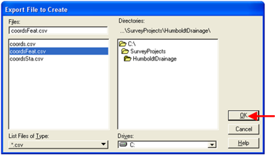
This will return processing to the “Export GPK Points …” dialog, as shown below.
- In the Output Format area, you can select the desired attributes for each point. You can also select the preferred display order for the text file column data in the Output file.
In the center of the dialog box, use the drop-down arrow to select the Compute Station value from Chain option, as shown.
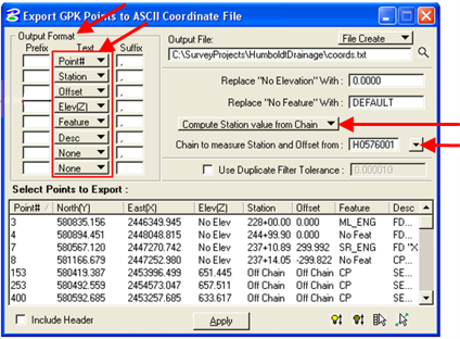
Use the next drop-down arrow to select the Chain name (horizontal alignment) that you would like the stationing and offsets measured from.
- You can sort the points listed in the “Select Points to Export” area by clicking on any of the column headings to sort by that point type.
Example: To sort by the Feature code, click on the Feature heading, as located by the red arrow at the right.
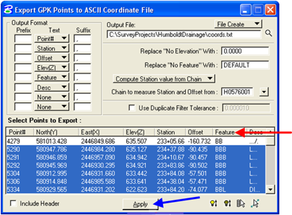
To select the points that are to be included in the Station Offset report, highlight the desired rows of data by to be included in the list. To highlight several points, click on one of the points to be selected and then hold down either the Shift or Ctrl keyboard key while selecting additional points.
When the selection is complete click the Apply button.
- The Station Offset report has now been created. Because of the “txt” file extension used in the Output File area of the example above, the output produced is in an ASCII text format. A file of this type can be opened with Microsoft Word, Notepad, WordPad, or the PFE32 text editor. Because the Select Points to Export list (above) was sorted by the Feature column, the “txt” file will also be sorted by the Feature.
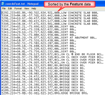
- Sorting by the Feature is often the best way to select points to highlight for a report. The information can be sorted by any feature for the purpose of locating and selecting the desired points for the Output List. After the points have been selected and highlighted, they can be resorted (if desired) to produce a different order for the final Output List.
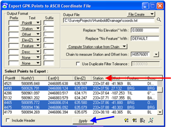
In the example list below the same points were selected as in the example listing above, but after the points were selected, they were resorted by the Station value prior to creating the list. After highlighting the points in the Select Points area, resort by clicking on the Station heading and then press the Apply button to create the list.
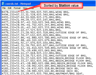
- The points shown in the “txt” file listing at the right are essentially the same as in the list above except that they are sorted by Stationing.
- If you would rather look at the station offset report in Microsoft Excel, you can change the file extension to “csv”, as shown by the red arrow at the right, then click the Apply button to produce the list.
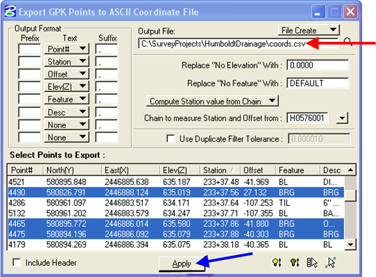
- This will create a comma delineated file that can be opened easily in Excel. This is the same points list sorted by Feature.
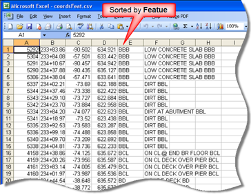
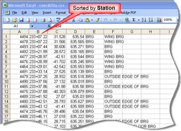
- These are the same points again, sorted by Station in Excel.