Content Information
On this page...
All pipe culverts must be shot at enough locations to record pertinent information from one end of the structure to the other. This includes the flowline (PIP), dirt flowlines (PRO) and the location of the pipe (SOP). When referring to the end of a pipe, when that pipe has an apron, the end of the pipe is the joint where the apron attaches to the last pipe segment.
Top and side view examples show of all shots necessary for a pipe culvert. (Shots are located.)
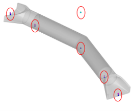
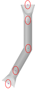
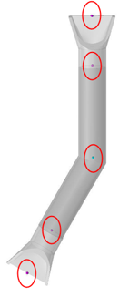
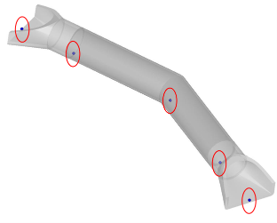
- The feature code PIP is used to show the flowline of the pipe at the end of pipe, the end of the aprons (if attached) and any horizontal or vertical breaks in the pipe. A survey chain should be created from these points. The point descriptions should be “INLET FLOWLINE”, “OUTLET FLOWLINE”, “INLET END OF APRON”, “OUTLET END OF APRON” and “BREAK IN PIPE”.
Top and side view examples show of all shots necessary for the flowline of a pipe culvert. (Shots are located.)
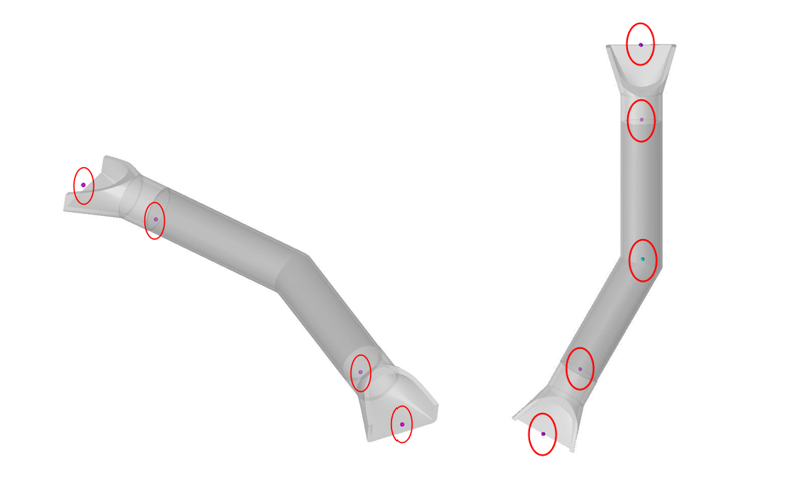
- If the pipe contains a considerable amount of dirt, shots should be taken to record the depth. The feature PRO should be taken at the end of the pipe, end of the apron or at the location of the dirt depending on the situation. The point description should be “DIRT PROFILE”.
Top and side view examples show of all shots necessary for the Dirt Profile of a pipe culvert. (Shots are located.)
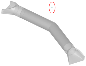
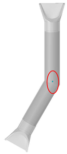
- A point with the feature code of SOP should be created to show the location of the pipe. The location of the SOP will be at the intersection of the pipe and the horizontal roadway alignment at the elevation of the roadway. If the pipe does not cross centerline, the SOP point should be at the intake flowline location at the end of the pipe. The description of the SOP point should include the pipe ID, dimensions, condition, skew angle, drainage area and terrain type (F= FLAT, R = ROLLING, H= HILLY, VH= VERY HILLY).
Top and side view examples show the shot necessary for the pipe location. (Shot is located.)
Example:
PIP51, 24” X 44’ RCP, FAIR CONDITION FILLING W\ DIRT,
SKEW ANGLE= 44° RT AH, DA = 33 AC - H
- The first item entered in the description for each pipe shot is an identifier. The easiest method of identification is to label the first pipe surveyed as PIP1. The number will increase sequentially for each pipe surveyed thereafter. This identifier will be used by the customer to group all shots together that are associated with each drainage structure.
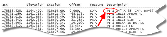
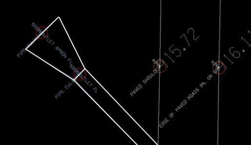
- The final product for each pipe in MicroStation should show the outline of the pipe (its diameter) and the outline of any aprons used on the pipe. There are two different methods that can be used to accomplish this. The first method is to use the points shot in the field and create the pipe and apron outlines using MicroStation tools. The other option is to outline the pipe and aprons in the field with survey shots. A survey chain should be created using the PIP feature for the pipe and another chain for each apron that is attached. The field shots needed for the outlining is in addition to the PIP shots showing the pipe’s flowline. After the outline is drawn, the PIP survey chain for the flowline may be deleted from the MicroStation File.
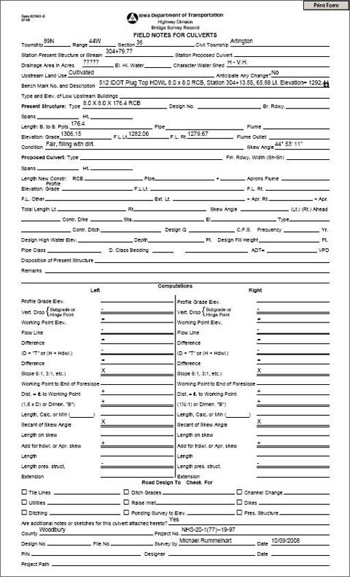
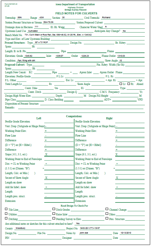
- A Form 621001-E (Pink Sheet) must be completed for each pipe that crosses a roadway.
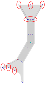
- All box culverts must be shot at enough locations to draw the outline of the culvert in the plan view and to show all of the breaks and flowlines pertaining to the culvert. Here is a top view of all of the shots necessary for this example.
Top and side view examples show many necessary shots for a box culvert. (Several shots are located.)
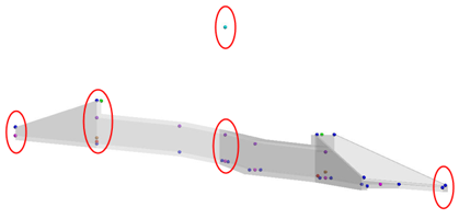
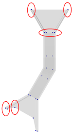
- The CUL feature should be used for the outlining of the culvert to be shown in the plans. All shots should be on the inside of the culvert. One survey chain should be created outlining each apron with another survey chain created to show the box. Each horizontal or vertical break in the box must be shot. The description for each shot should be the shot location.
Top and side view examples show many necessary shots for a culvert. (Several shots are located.)
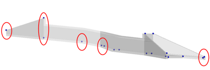
- The flow line of the culvert should be shot and stored using the PRO feature and a description of FLOWLINE. The last\first shot on the inlet side should have a description of INLET FLOWLINE and the last\first shot on the outlet side should have a description of OUTLET FLOWLINE These shots should be taken in the center of the box at every horizontal and vertical break.
Top and side view examples show many necessary shots for a culvert flowline. (Several shots are located.)
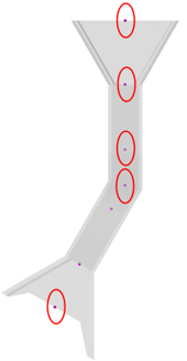
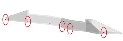
- If the culvert contains a considerable amount of dirt, a PRO shot should be taken on the top of the dirt at the center of the box at each culvert opening containing the dirt. The description for this PRO shot should be INLET DIRT FLOWLINE or OUTLET DIRT FLOWLINE depending on where the shot was taken.
Top and side view examples show the dirt flowline shots necessary for a box culvert. (The shots are located.)
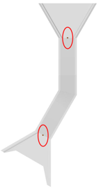
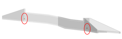
- There needs to be a PRO shot for the top of the opening on each end of the culvert and also at each horizontal or vertical break in the culvert. The description for this PRO shot should be INLET TOP OF OPENING, OUTLET TOP OF OPENING, VERTICAL BREAK TOP OF OPENING, etc.
Top and side view examples show several necessary shots for a culvert profile. (Some shots are located.)
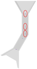
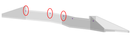
- A shot should be taken at the center back edge of the headwall using the PRO feature. The description for these shots should be BACK OF HDWL. The description should also include width of headwall, length of apron and width and length of each wing.
Top and side view examples show the shots necessary at the Back of Headwall. (The shots are located.)
Example:
BACK OF HDWL, 8 HDWL, 14.0 APRON>, .8 X 23.0 FLARING WING BACK.8 X 14.0 FLARING WING AHEAD, DOG EARS & FROST TROUGH
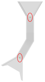
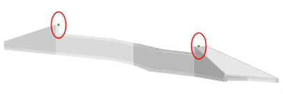
- A shot on the top of the frost trough should be captured on the inlet and outlet of each culvert using the PRO feature. The description of this point should be INLET TOP OF FROST TROUGH or OUTLET TOP OF FROST TROUGH.
Top and side view examples show the necessary frost trough shots. (The shots are located.)
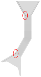
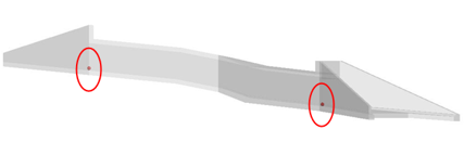
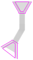
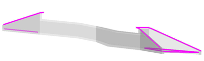
- To make the TIN more accurate, survey chains should be shot around the inlet and outlet of the culvert. The feature code for these survey chains should be BL for breakline.
Top and side view examples are shown.
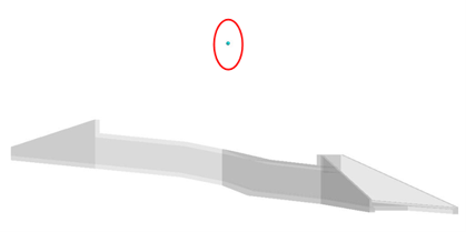
- The location point for the culvert is stored as an SOP feature. The location of this shot should be where the centerline of the culvert intersects the roadway alignment and at the elevation of the roadway. If the culvert does not cross the centerline, the SOP should be at the inlet flowline. The description of the SOP point should include the culvert ID, dimensions, condition, skew angle, drainage area and terrain type (F= FLAT, R = ROLLING, H= HILLY, VH= VERY HILLY).
Top and side view examples show the culvert “location” shot.
Example:
CUL62, 8.0 X 8.0 X 176.42 RCB, FAIR CONDITION FILLING W\ DIRT,
SKEW ANGLE= 44° RT AH, DA = 33 AC - H
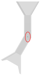
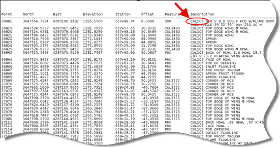
- The first item entered in the description for each shot associated with the culvert is an identifier. The easiest method for naming the identifier is to use CUL1 for the first culvert surveyed, with the number increasing sequentially for each culvert surveyed after that, e.g., CUL2, CUL3, CUL4. This identifier will be used by the customer to group all shots together that are associated with each drainage structure.
- A Form 621001-E (Pink Sheet) must be completed for each culvert that crosses a roadway.