
Content Information
On this page...
The current topographic survey processes utilized in the Preliminary Survey Section allows the customers of these surveys to have all field information available to them within MicroStation and GEOPAK files.
NOTE:
All survey instructions and any other survey information not included in this document can be found in Chapter 40 of the Design Manual.
There are three different methods for using this information, depending on the need. Each of the methods builds on the previous one.
The first and easiest method for using the survey data is to view the information that is displayed on the used levels, as shown below.
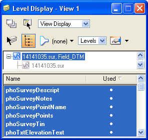
As displayed below, these levels show:
- the circle representing the shot location,
- the description of the type of shot collected,
- the shot number, and
- a detailed note.
An elevation is also displayed if the shot was collected for the purpose of ground elevation.
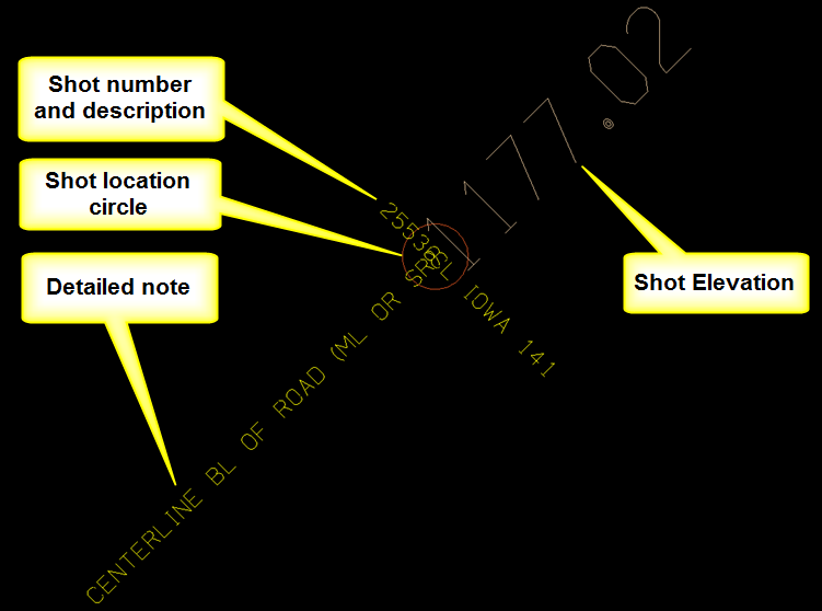
The above listed information is the only information available in the MicroStation file without using the GEOPAK software.
The second way to use and evaluate the survey information is to use GEOPAK COGO. The Prelim Survey “.gpk” file must be copied to the design directory that contains the other “.gpk” files.
The Geopak program is initiated from the MicroStation tool bar menu as follows:
Applications > GEOPAK > Activate GEOPAK from the MicroStation tool bar.
After Geopak is activated, the COGO program is started, as follows:
Applications > GEOPAK > ROAD > Geometry > Coordinate Geometry
This will display the Coordinate Geometry dialog, as shown below. Click the “Browse” magnifying glass icon () to select the appropriate Prelim survey “.gpk” file, (Job). Complete the other data entry fields, as necessary, and click the OK button.
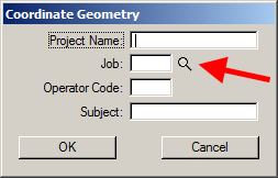
This will display the Coordinate Geometry dialog. The COGO Navigator dialog can be accessed as shown by the arrow at the right.
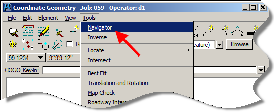
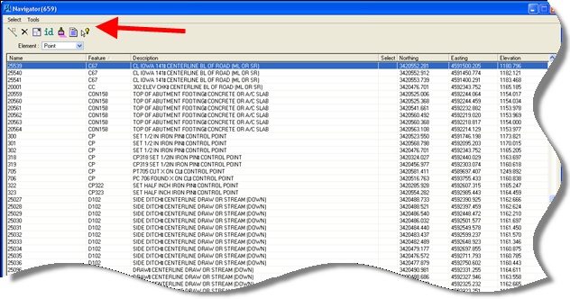
The Navigator dialog should display a listing of points similar to that shown below. To display information about a point, select the point in the Navigator list and then select any of the data information tools, located by the red arrow below. This should display point information in the Coordinate Geometry list box, above.
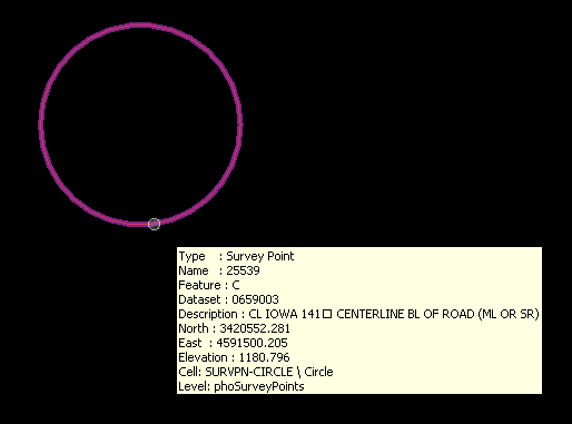
The third way to use and evaluate the survey information is to utilize the GEOPAK Survey Project tool. By simply “hovering” the curser over any Survey Point, this tool will provide the most comprehensive amount of information about that point as simple pop-up information attached to the cursor.
To start GEOPAK Survey, (with GEOPAK already started), select:

Applications > GEOPAK > SURVEY > Survey
This will open the GEOPAK Survey tool bar, as shown above.
To open a GEOPAK Survey project, choose Project > Open from the Survey dialog toolbar, shown above. This will display the Project Open dialog, as shown below.
Browse to the appropriate PrelimSurvey folder and select the “shortcut…” for the “.prj” file, as shown below.
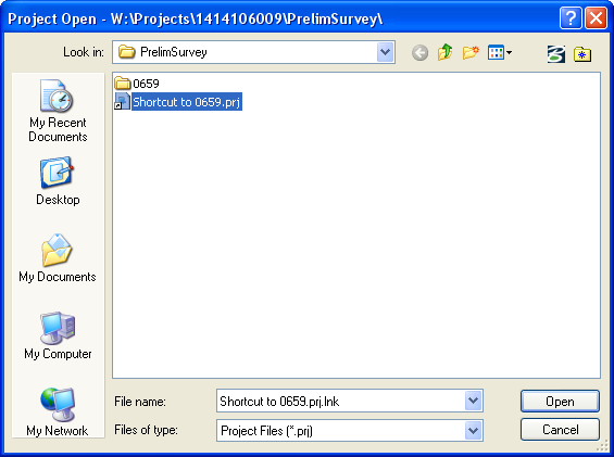
Accept any messages warning that the project is read only.
The Survey dialog should now show the Survey and Photogrammetry (SAP) number on the title bar, as shown below.

To eliminate clutter, the display of all “phoSurvey…” levels can now be turned off, except for the two levels listed below:
phoSurveyPoints
phoSurveyPointsNonDTM
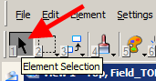
Select the MicroStation Element Selection tool, as shown below.
By moving the MicroStation cursor over any of the survey shots, a complete list of information about that shot will be displayed, as shown at the right.
Back to top