
Content Information
On this page...
The vertical profile of an edge return should be flat enough to provided a comfortable transition between the cross slopes of two roadways, and yet not so flat to cause a drainage problem. This section provides guidance on how to develop an edge profile which is smooth, constructible, and prevents drainage problems. Examples are provided detailing the steps involved in developing an edge profile.
Back to topGuidance for Intersections without Curb Ramps
An edge profile for an intersection without curb ramps should incorporate the following guidance:
- Minimum cross slope of 0.5%.
- Maximum cross slope of 6.0%.
- Cross over crown breaks should be less than 5% and with preferred values less than 4%.
- Desirable change in cross slope is 1% in 12.5’.
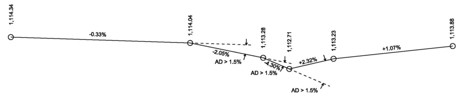
- The algebraic difference in grade lines along the edge profile at the control points should not exceed 1.5%. Grade differentials greater than 1.5% are difficult for contractors when forming an intersection return.
Guidance for Intersections with Curb Ramps
Guidance for an edge profile with curb ramps will be issued later.
Back to topSteps to Develop an Edge Profile
- Place longitudinal jointing lines
- Determine tie-in elevations
- Locate control points
- Determine elevation of control points
- Develop edge profile and adjust elevations to limit algebraic difference in grades
- Check cross slope
- Check change in cross slope
Example 1-Typical Rural Ramp Intersection
The first example is an intersection of a ramp and a side road.
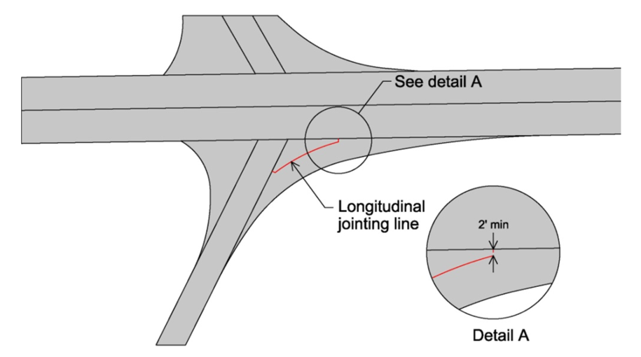
Step1: Place longitudinal jointing lines
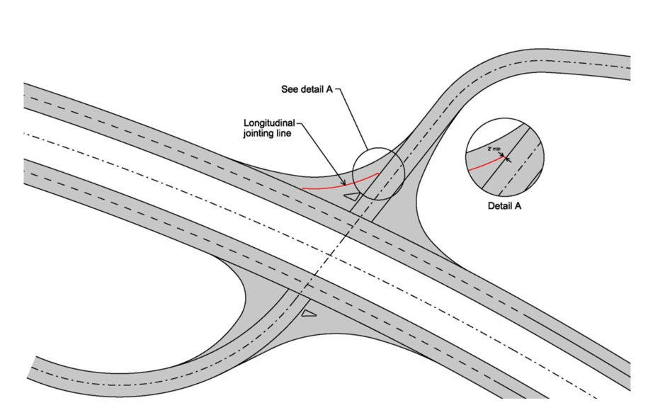
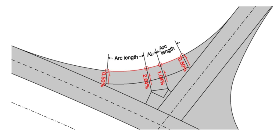
Locate longitudinal jointing lines. The joint line is used as the staking line. It should be concentric to the edge of the return and offset 10’ – 16’.
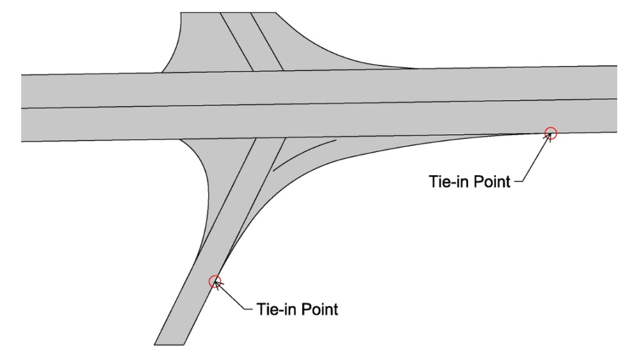
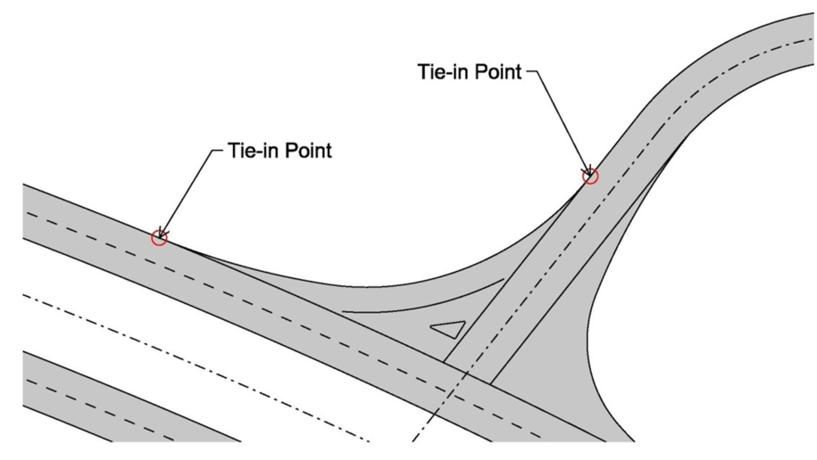
Step 2: Determine tie-in elevations
Calculate the edge of the pavement elevations at the tie-in points at each end of the return. These elevations are of the beginning and ending points of the edge profile.
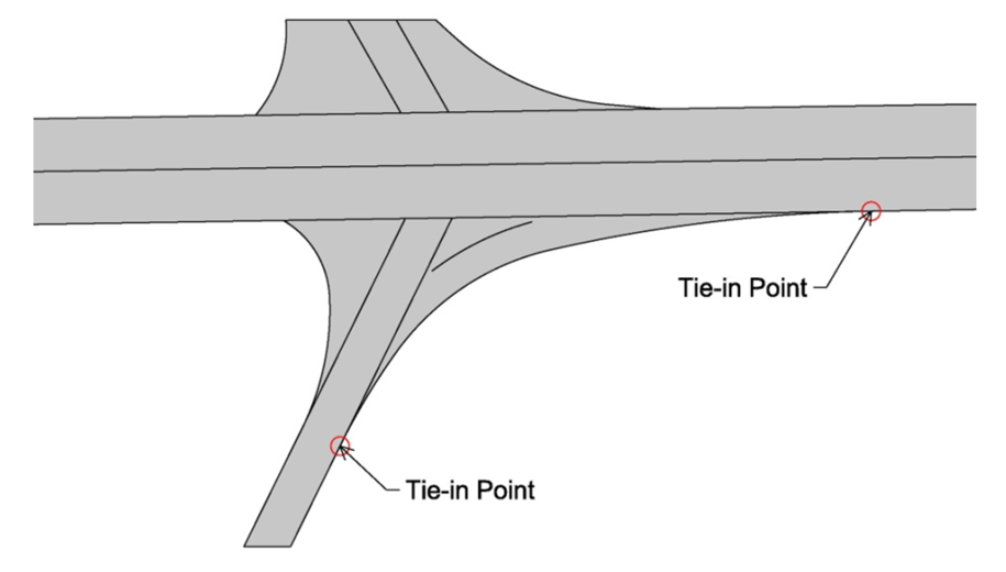
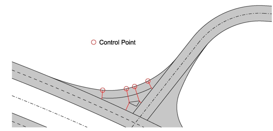
Step 3: Locate control points
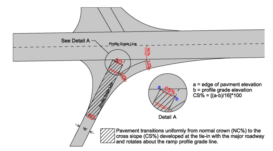
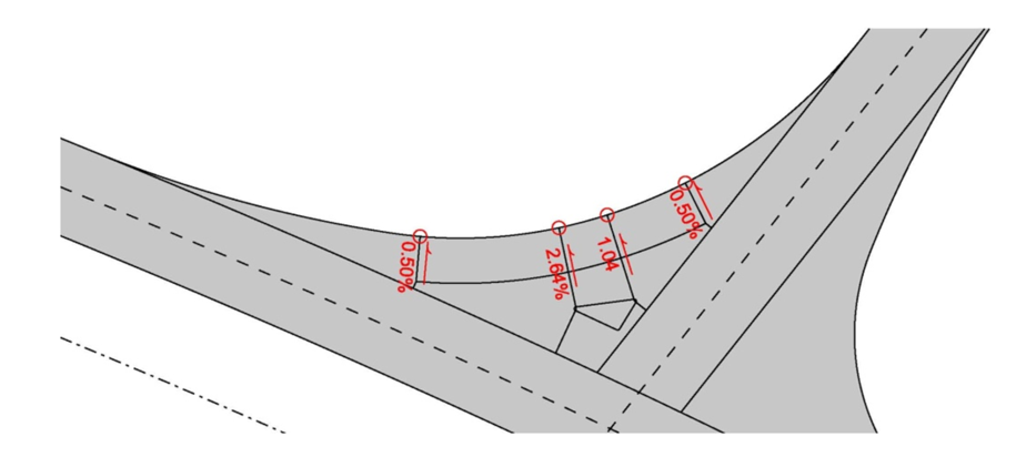
Step 4: Determine elevation of control points
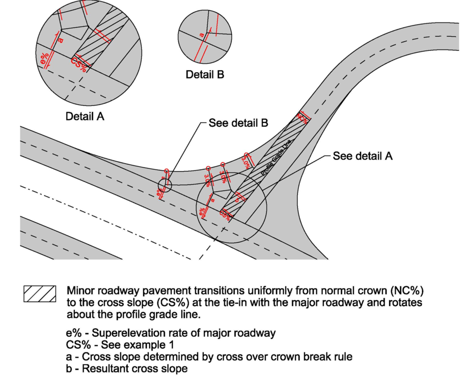
Use the NC% of the side road and the CS% of the ramp to determine the elevations at each end of the staking line.
Use a transverse cross slope of 3% on the return to determine the initial elevations of the control points.
Step 5: Develop edge profile
Use the elevations at the tie-in and control points to develop adjacent initial grade lines. Then adjust the elevations until the algebraic difference between adjacent grade lines is 1.5% or less.
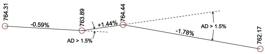
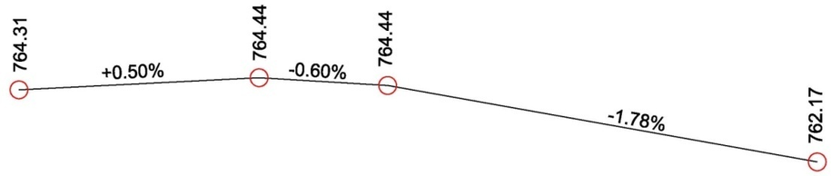
Intermediate VPI points are sometimes needed to establish an edge profile with grades lines with algebraic difference of 1.5% or less.
The additional VPI points should be added at even 10’ increments along the edge return, since forms are normally 10’ long.
Step 6: Check cross slope
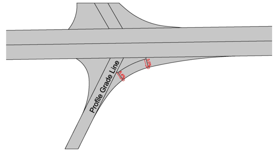
After adjusting the elevations of the control points, calculate the resulting transverse cross slope on the return. The resulting cross slopes should preferably be in the 2%-4% range, with 0.5% and 6.0% being the minimum and maximum cross slopes.
If a cross slope is greater than 6.0% or less than 0.5%; adjust the elevation of the control point and revise the edge profile.
The resulting cross slopes should not create a cross over crown break of 5% and preferably less than 4%. Inverted crown breaks should be avoided.
Several iterations of adjusting the control point elevations may be necessary to optimize the edge profile, transverse cross slopes, rate of change and cross over crown break.
Cross slopes should create smooth transitions, but should not fluctuate back and forth. In other words, cross slopes should gradually increase and/or decrease, but should not alternate at successive control points.
Step 7: Check change in cross slope
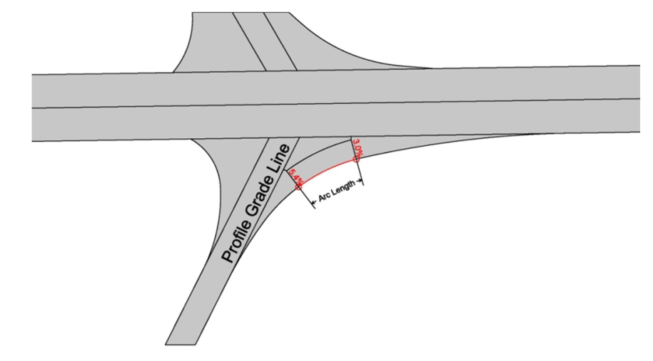
The change in cross slope between transverse staking lines should be less than 1% in 12.5 feet (or 0.8% in 10’).
If the change in cross slope is greater than 1% in 12.5 feet; adjust the elevation of a control point, revise the edge profile, and calculate the resulting cross slope.
Back to top
Example 2-Intersection of a major and minor roadway
Step1: Place longitudinal jointing lines
The second example is of an intersection of a major and minor roadway. The intersection of the two roadways occurs within a horizontal curve of the major roadway and the minor roadway has a stop sign island.
Step2 : Determine tie-in elevations
Step3 : Locate control points
Step 4 : Determine elevation of control points
Step 5 : Develop edge profile

Step 6 : Check cross slope
Back to top