Content Information
On this page...
A PCC overlay is a paving process where a new concrete pavement is placed over an existing PCC, HMA, or composite pavement. These overlays are thinner than a new full depth PCC pavement because they rely on the underlying pavement for structural support.
Overlays can be broken down into four basic types:
Concrete on Concrete Bonded (COC-B)
Concrete on Concrete Unbonded (COC-U)
Concrete on Asphalt Bonded (COA-B)
Concrete on Asphalt Unbonded (COA-U)
Most overlays on the interstate and primary systems will be designed as an unbonded overlay (COC-U or COA-U) by either placing the PCC overlay directly on a pavement with an asphalt surface (full depth HMA or composite pavement) or placing a stress relief course/fabric bond breaker on an existing PCC surface and then overlaying that with new PCC.
Unbonded or Bonded PCC Overlays on HMA Surfaces
Unbonded PCC overlays
PCC overlays that are six inches thick or more are considered an unbonded overlay. Because these overlays are unbonded from the underlying HMA pavement, lining the proposed joints in the PCC overlay up with any joints or cracks in the existing pavement is not necessary. This type of PCC overlay will typically have larger panel sizes since they are less likely to crack due to the increased thickness.
Bonded PCC overlays
PCC overlays that are less than six inches thick are typically considered to be a bonded overlay. Because the PCC overlay is placed on HMA, it is not necessary to saw the joints on the overlay at the exact locations of the existing joints or cracks in the existing pavement. This type of overlay will also typically use smaller panel sizes to help minimize the potential for cracking and debonding of the PCC overlay from the underlying HMA.
On all unbonded PCC overlays, the existing HMA surface should be profile milled to provide a uniform surface to place the overlay pavement. This helps minimize the overrun of the concrete quantity on the project by removing imperfections from the surface. The profile is generated by the Contractor as part of the Construction Survey, Location Survey bid item if a proposed profile is not provided in the plan.
On all pavements with HMA milling, the profile should at a minimum be low enough to remove any rutting or other defects in the surface (typically one inch or less). Depending on the structural condition of the existing pavement and HMA thickness, additional milling depth beyond the ruts may be considered to lower the profile of the roadway. This minimizes the grade raise caused by the PCC overlay. A minimum of four inches of existing HMA should be left in place. This additional milling thickness should be shown on the typicals and/or noted in the estimate reference information for the scarification bid item. The profile should be set so the milled surface ends up near the center of a lift to minimize debonding of the lift being milled from the lift below.
On all bonded or unbonded PCC overlays on an existing HMA surface, any existing or new PCC patches need to have a bond breaker applied before placing the PCC Overlay. This prevents bonding between the new and old concrete and can be accomplished by installing a pavement interlayer geofabric or applying two coats of white curing compound. On bonded PCC overlays debonding of the patches is necessary to prevent reflective cracking from the patch into the PCC overlay.
Unbonded PCC Overlay on Existing PCC Surfaces
When an unbonded PCC overlay is placed on an existing PCC pavement, a means to prevent bonding between the two layers is necessary. On the interstate and primary systems this is usually accomplished with an HMA stress relief course. The HMA stress relief course is typically one inch thick and is placed prior to the PCC overlay. On the secondary road system, a pavement interlayer geotextile fabric may be used as the bond breaker. This material is either nailed or glued to the existing PCC pavement prior to the PCC overlay.
Bonded PCC Overlay on Existing PCC
Bonded PCC overlays on existing concrete pavements rely on the bond between the overlay and the underlying pavement to achieve the desired structural capacity. Because the two layers are bonded together, it is imperative that the locations of all joints and cracks must be noted and sawn into the overlay in the exact same locations to prevent the overlay from experiencing random cracking. Due to the difficulty in lining the joints up and the potential for cracking, the use of bonded overlays is not recommended for projects on the interstate and primary systems.
Back to topDesign
When preparing plans for the overlay, typicals of the existing pavement should be included. This is especially important on projects where the existing surface will be milled before the overlay is constructed. As-builts of the plan and profile sheets should be included to provide the existing alignment and survey data, or new plan and profile sheets with a new profile should be provided using new survey data. If a proposed profile is not included, the contractor will need to use the as-built information and develop a proposed profile for the project.
Vertical Profile
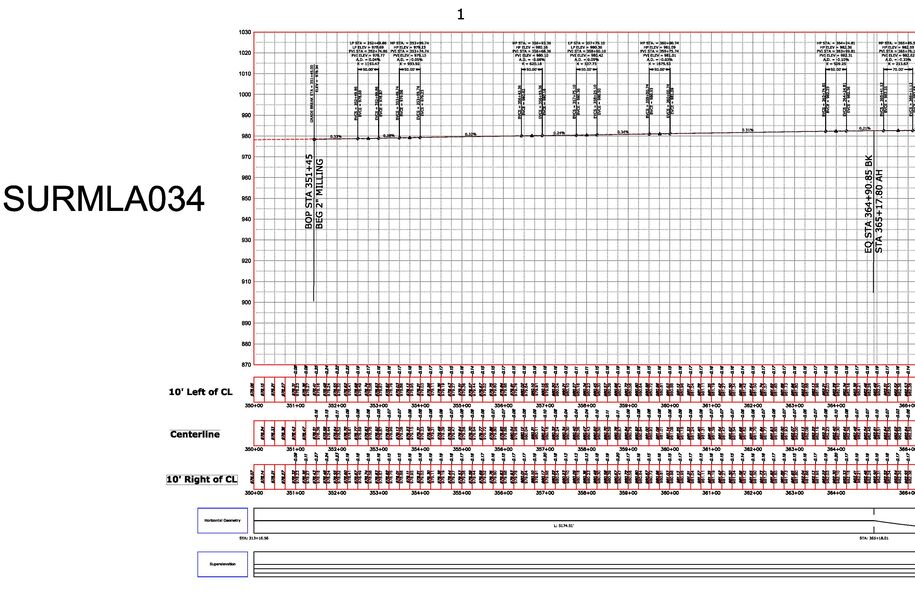
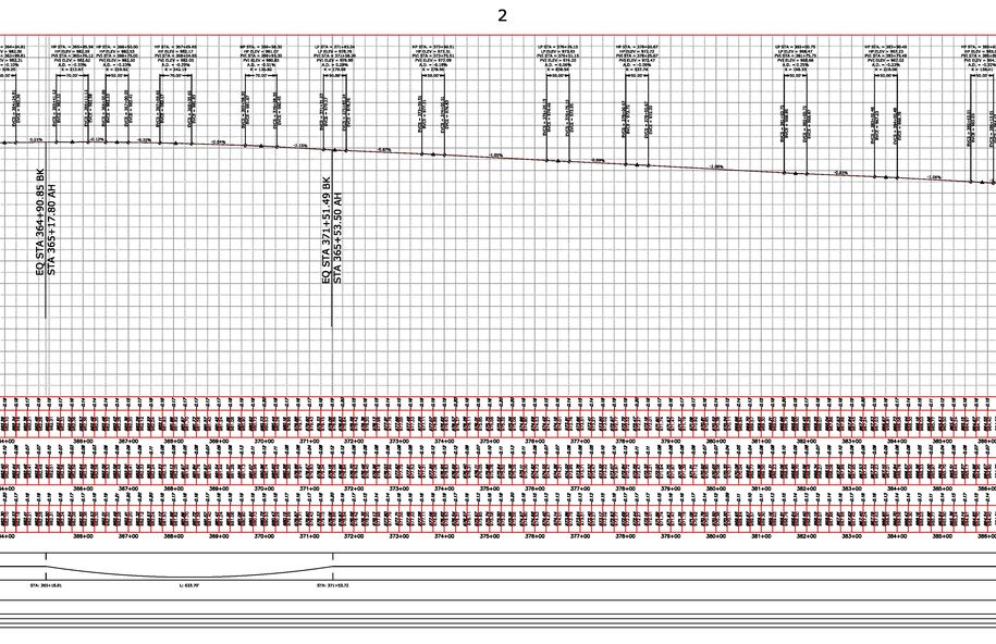
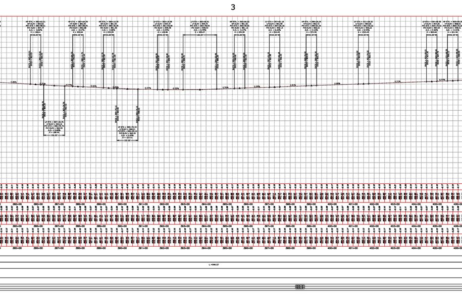
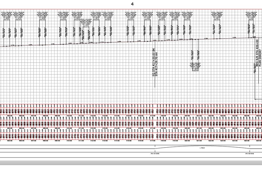
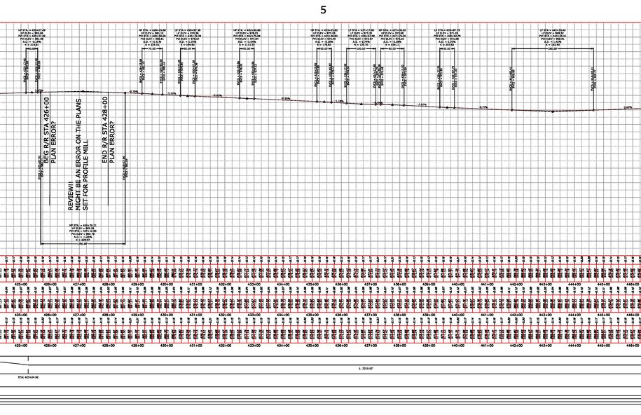
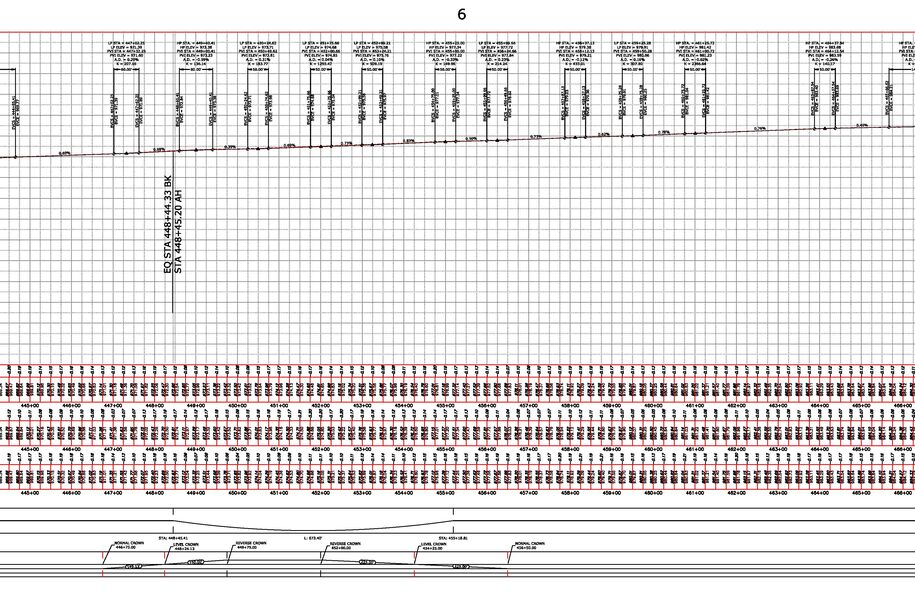
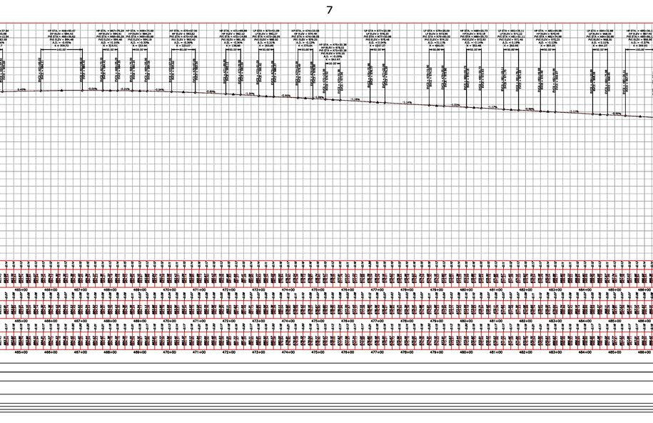
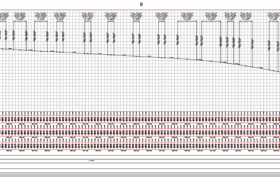
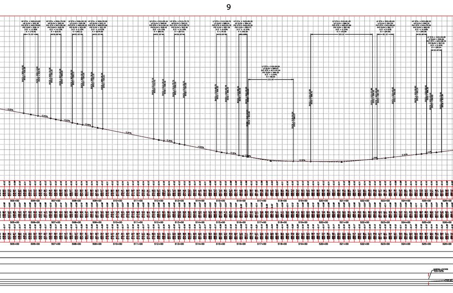
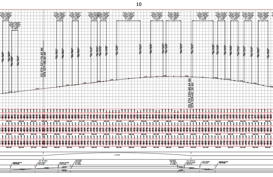
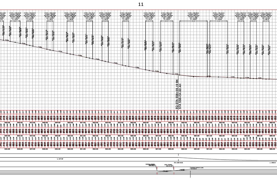
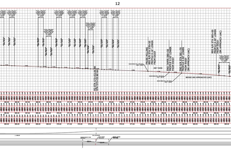
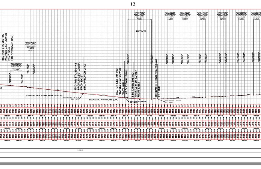
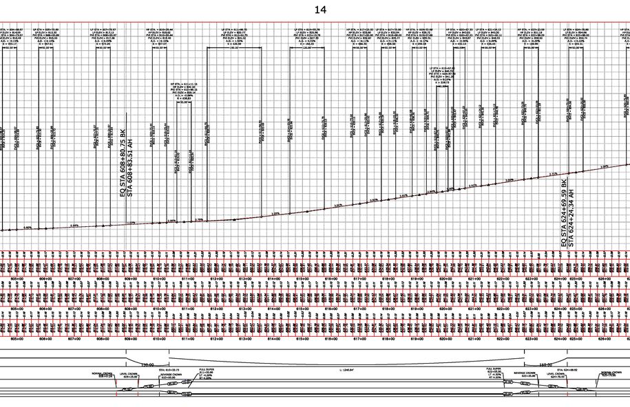
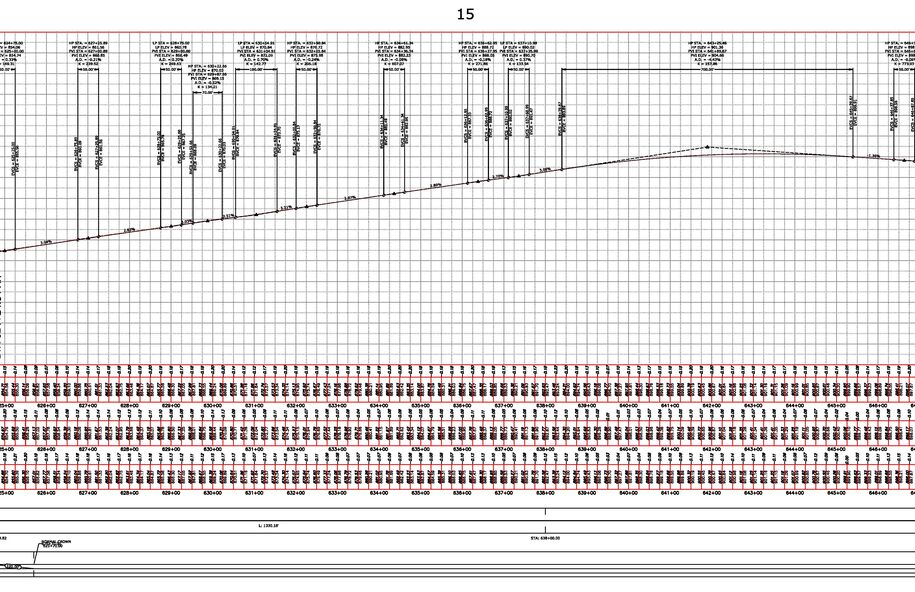
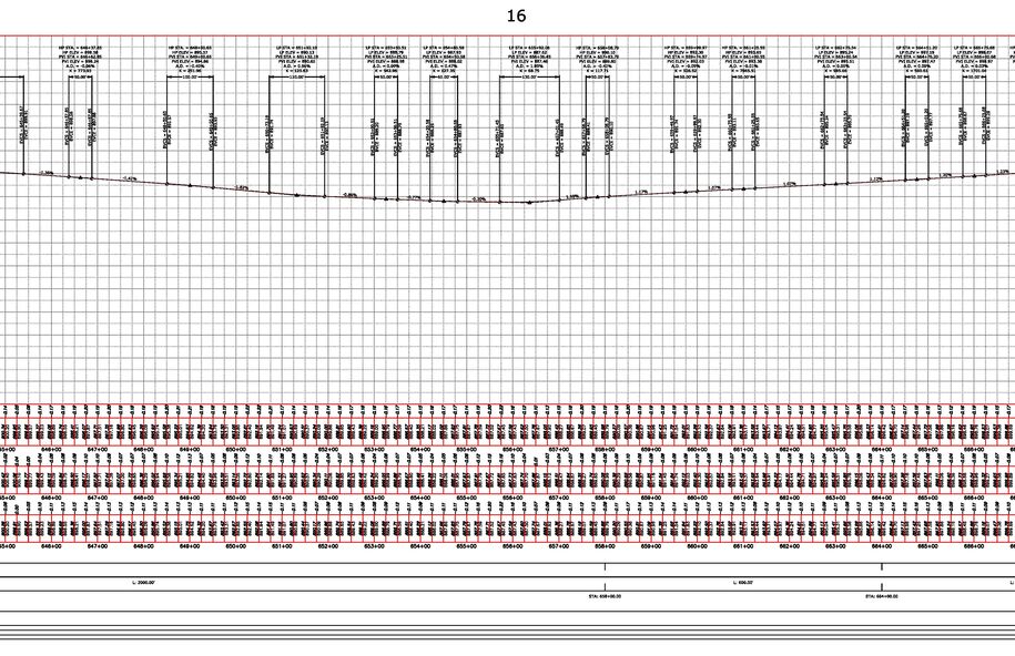
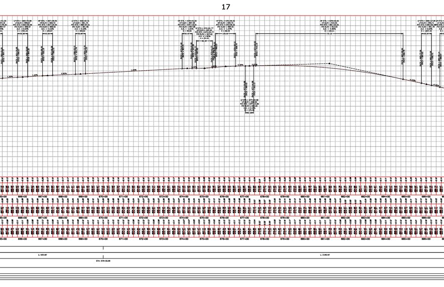
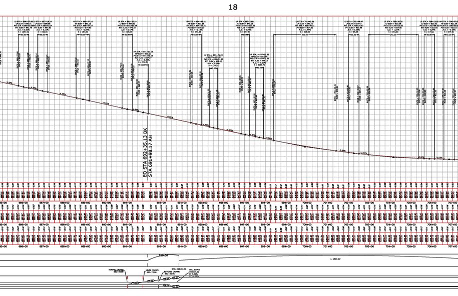
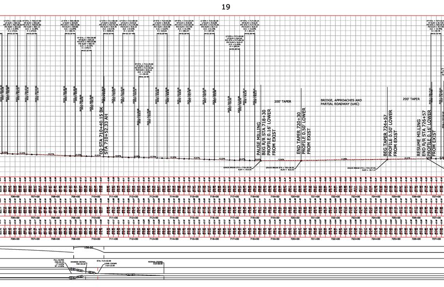
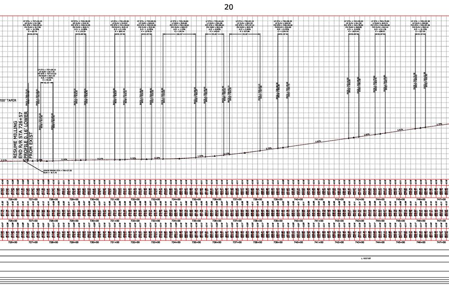
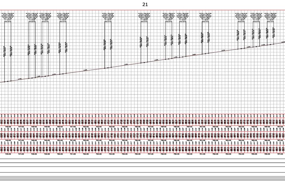
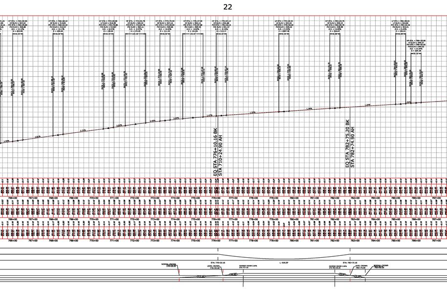
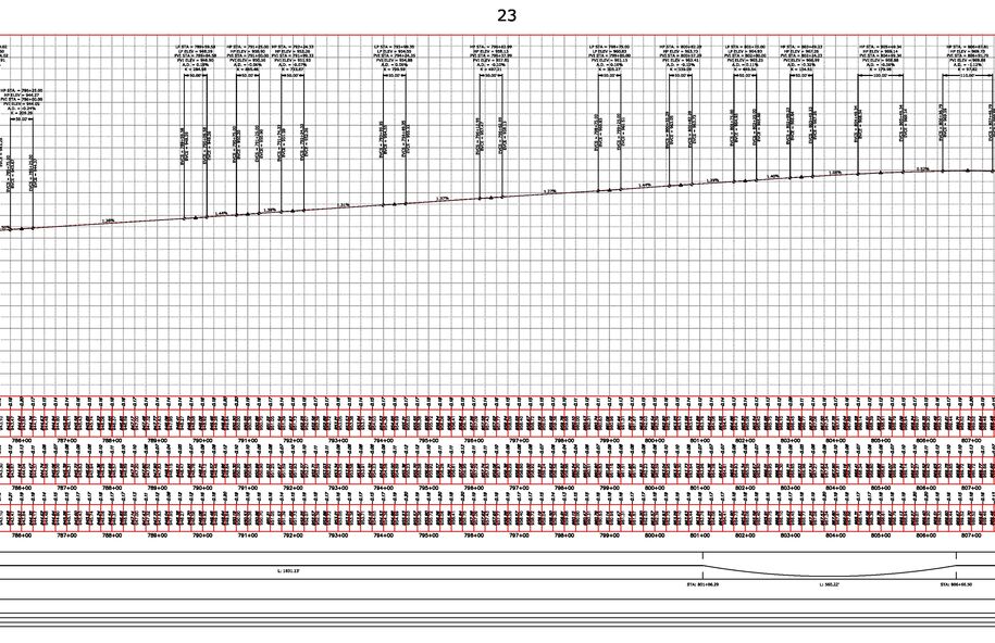
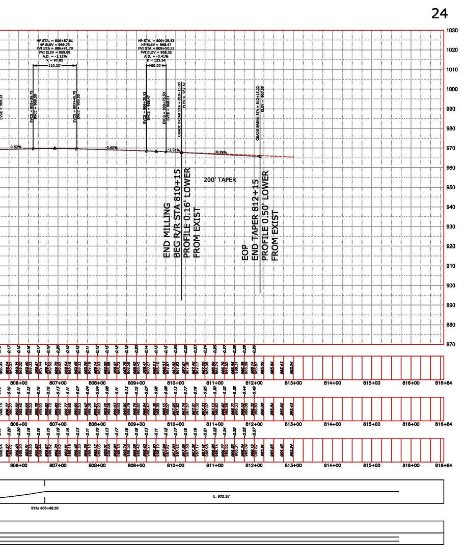
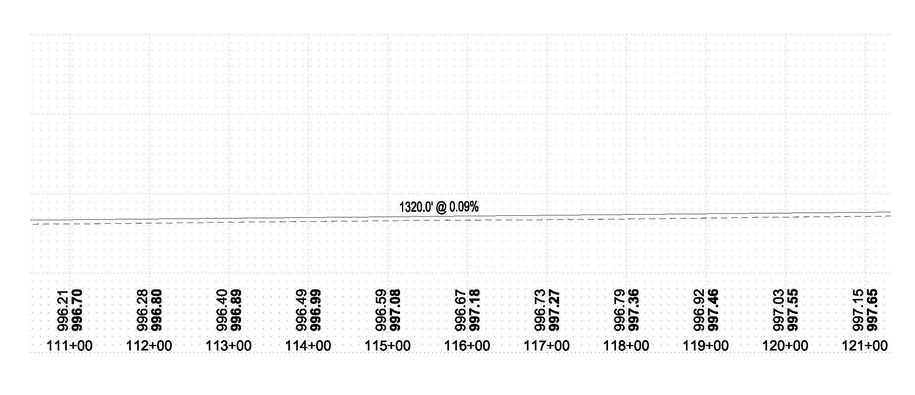
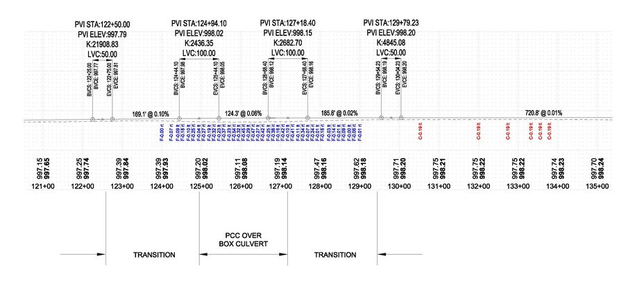
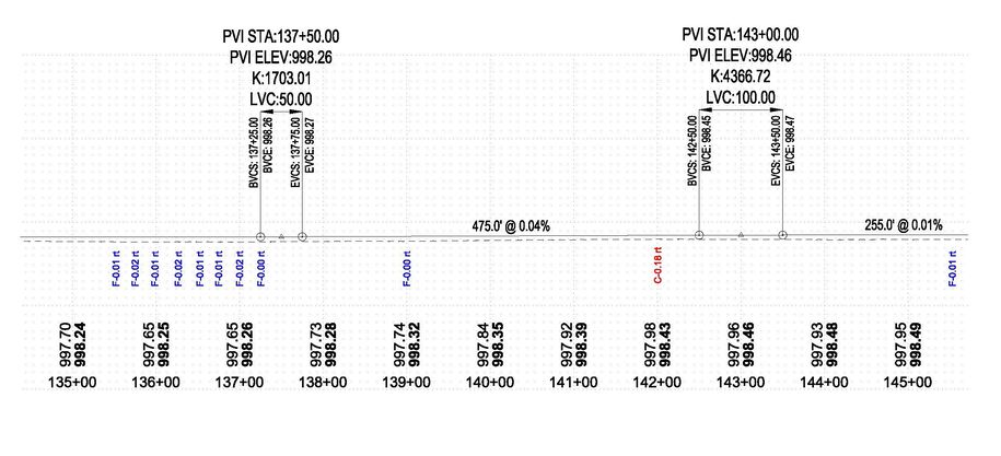
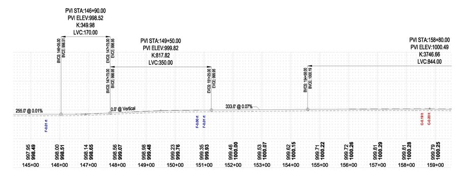
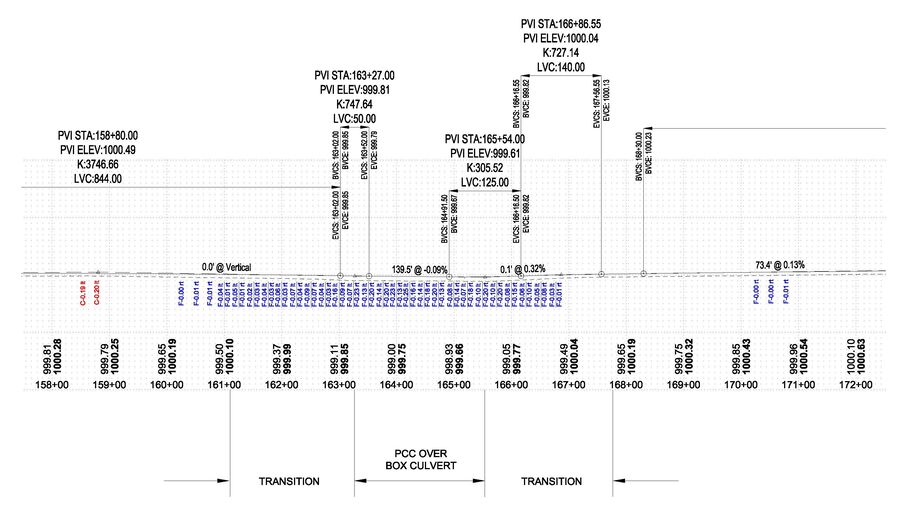
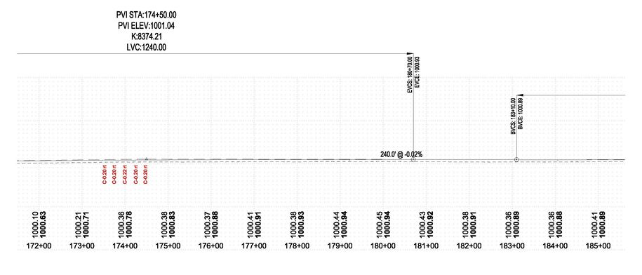
To be able to construct most PCC overlays, developing a proposed profile is necessary. This ensures that the overlay will have proper thickness and will also help to control overrun of the volume of concrete used for the project. The existing pavement is surveyed to determine conditions in the field. With the survey complete a proposed profile is created. The proposed profile is then adjusted until it fits the existing pavement survey profile to create a best fit profile.
When developing the best fit profile, the original vertical geometry should be used as a starting point. The location and/or elevation of VPIs, as well as the vertical curve length, can be adjusted as needed to make the profile fit the survey data. Additional VPIs can be added to improve the fit of the profile to the existing survey; however, they should not be added to the extent that the entire profile is a string of vertical curves. These VPIs should also include a vertical curve with a minimum length based on the design criteria for the roadway. Adding VPIs without vertical curves should be avoided to minimize impacts to the smoothness of the pavement. An exception to this is at the beginning and ending of transitions to existing pavement or at bridge approaches.
Example 1 Best fit profile no additional VPIs
Example 2 Best fit profile with additional VPIs
Once the best fit profile is finished, it is offset vertically to define the top of the overlay at the profile grade point. This offset also needs to account for the thickness of any milling needed or the thickness of a new stress relief course so that the design thickness of the overlay is achieved. On bonded overlays the offset will be the thickness of the overlay.
For projects where the contractor is developing the proposed profile, it will need to be reviewed and approved by the Resident Construction Engineer prior to use for construction purposes. Which format will be used should be discussed at the preconstruction conference when the project starts. The profile can be submitted using one of the following formats:
- The existing and proposed profiles can be placed on plan and profile sheets and submitted in PDF format
- The existing and proposed profiles can be placed on a scroll and submitted in PDF format
- The design file containing the existing and proposed profiles can be submitted in a MicroStation Connect format.
Overlay Pavement Thickness
When determining the required thickness of the overlay, the first thing to consider is whether the overlay will be of a bonded or unbonded design. An unbonded design considers the underlying pavement for support only, so the overlay must have sufficient thickness to provide all the necessary structural capacity. When designing the thickness for a bonded overlay, both the existing pavement and the proposed overlay contribute to the structural capacity of the pavement, which usually results in a thinner design thickness for the overlay.
The typical design thickness of an unbonded overlay on the primary system is 6 inches. This thickness has performed well on past projects and allows the use of tie steel when adding shoulders or auxiliary lanes. Thinner overlays are not recommended because they do not provide sufficient cover for tie steel, which makes jointing more difficult.
Certain conditions may require a thicker overlay, such as higher truck volumes or condition of the underlying pavement. Projects on the interstate system should be handled on a case-by-case basis due to the highly variable conditions.
The Pavement Design Engineer in the Construction Materials Bureau should be contacted for assistance with the thickness determination of all PCC overlays, shoulders, turn lanes, climbing lanes, and passing lanes.
Fiber Reinforcement
The concrete mix for overlays less than eight inches thickn should contain synthetic macrofibers at a rate of four pounds per cubic yard. The function of the macrofibers in the mix is to help hold cracks that may form tightly closed. In overlays less than eight inches thick, the macrofibers take the place of dowel bars and tie bars where it is not practical to install them. This is important because the macrofibers help hold the panels together and minimize panel migration which has been observed on overlays with thinner thickness and no macrofibers in the concrete mix. Overlays eight inches thick or more may use either macrofiber reinforcement at a rate of four pounds per cubic yard or CD joints transverse joints and L joints longitudinally.
Pavement Width
Projects should be designed so that the driving lanes and any paved shoulder can be paved all in one pass. Most contractors have equipment that is capable of paving 36 feet wide in one pass, which makes this possible. This will ensure that the macrofibers in the mix will be available to tie the slabs together across the longitudinal joints. Most overlays on the primary system will be 36 feet wide and will include two 12 foot wide driving lanes and two 4 foot or 6 foot partial width paved shoulders.
When projects include climbing lanes, passing lanes, or offset right turn lanes (auxiliary lanes), the shoulder(s) should be six feet wide, and where an auxiliary lane exists, six feet of its 12 foot lane should be paved at its required thickness to maintain a 36 foot paving width. The remaining 6 feet of the auxiliary lane and any paved shoulder can then be added with a second pass of paving using a BT-2 joint to tie the slabs together. To avoid placing the longitudinal joint in the wheel path, 4 foot shoulders should not be paved through auxiliary lanes.
Pavement Cross Slopes and Superelevation
Cross slopes for the travel lanes, turn lanes, climbing lanes, and passing lanes of the proposed overlay should match the original design cross slopes whenever possible. Design cross slopes should also be used for the milling of the existing HMA surface or the slope of the top of the stress relief course for unbonded overlays. This will ensure a uniform thickness for the overlay.
The cross slope of the shoulders is typically 4%, but on narrow shoulders a 2% cross slope may be allowed to simplify paving.
The superelevation of the existing roadway may be reviewed as part of the overlay design. When this is to be done the amount of superelevation that is provided should be compared to the values in Section 2B of this manual. If the current superelevation is equal to or greater than the values in the table, then no adjustments are necessary. If the current superelevation is less than the values in the table, then the superelevation may be adjusted if deemed necessary.
Care must also be exercised when developing the transitions for any superelevation on the project because several changes have been made to how superelevation transitions have been applied to horizontal curves over the years. These changes, although subtle, can impact the thickness of the overlay.
Shoulders
The existing shoulder type and the proposed shoulder type will determine how the shoulders will be designed and constructed. Whenever possible paved shoulders should be paved with the overlay for the reasons stated above in the Pavement Width section.
New paved shoulder over existing granular shoulders
For existing granular shoulders, the minimum paved shoulder thickness should be 2 inches plus the thickness of the overlay. This ensures that a uniform thickness of shoulder is constructed and helps control the quantity of materials used for shoulder construction. An additional reason for the increased shoulder thickness is to provide additional strength for agricultural equipment that may be traveling on the shoulder. If core out is needed for accommodation of the shoulder and any shoulder subbase, it should be done with Class 13 Excavation. When a combination paved/granular shoulder is being constructed and the material cored out for the paved portion of the shoulder is clean gravel, consideration could be given to using this material to build some of the gravel portion of the combination shoulder.
New paved shoulder over existing paved shoulders
When the existing shoulder is paved, it should be overlaid using the same overlay thickness as the travel lanes. If milling of HMA is needed on the travel lanes, it will also be needed on the existing paved shoulders. If the existing shoulder is PCC and the proposed shoulder is designed as an unbonded overlay, a bond breaker will be needed between the overlay and the shoulder. This can be provided by applying a stress relief course on the existing shoulder in conjunction with the travel lanes.
New granular shoulder over existing gravel shoulders
When a new full width granular shoulder is to be placed on an existing granular shoulder, safety edge as shown on Standard Road Plan PV-3 may be included. Additional guidance on safety edge can be found in Section 3C-6. Additional Class A or Class B granular material is then placed on the existing shoulder to reach finish grade.
Jointing
Historically most PCC overlays in the state have been jointed using 6 foot by 6 foot square panels. This has proven problematic from a long term performance perspective and requires twice the amount of sawing and joint filling when compared to standard jointing practices. Additionally, this is problematic when turn lanes, climbing lanes, or passing lanes are incorporated with the work. Those lanes are typically jointed with a transverse joint spacing of 12 feet. That creates the potential for cracking at the intermediate 6 foot joint locations. As a result of this, all overlays 6 inches thick or more should use 10 foot by 12 foot panels. If the pavement has a 14 foot wide outside lane, the Pavement Design Engineer should be contacted for assistance. All joints should be filled to prevent non-compressible materials from entering, thus locking up the joints or causing pavement buckling.
Transverse Joints
When macrofibers are included in the concrete mix, the transverse joints should be C joints. When an overlay does not contain macrofibers and is eight inches thick or more, CD joints should be used.
Longitudinal Joints
Whenever possible the longitudinal joints on the overlay should line up with the joints on the original pavement to minimize the potential for longitudinal reflective cracking.
All longitudinal joints should be sawn at a depth of T/3 ± ¼ inches. Tie steel across the joint is not needed on overlays with macrofibers in the concrete mix. Overlays 8 inches thick or more that do not contain macrofibers in the concrete mix should use L-1 or L-2 joints, depending on overlay thickness.
Superelevated Curves
If the project involves superelevated curves and the amount of superelevation provided will be adjusted, the low side of the curve should be held at the design overlay thickness. The additional thickness required for the adjustment should be added to the high side of the curve, see Figure 1. If the existing shoulder is paved, the outside edge of the shoulder on the low side should be held at the design thickness. The additional thickness is added to the outside of the high side shoulder.
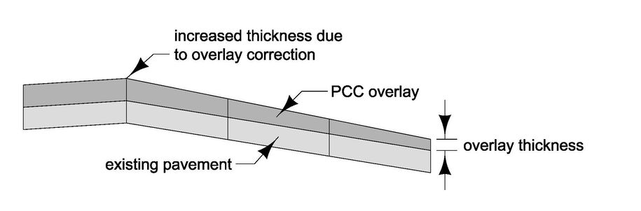
Because of the additional overlay thickness, sawing depths will also need to be adjusted through the curve. Sawcut depths are usually determined by the nominal thickness of the pavement; however, when a superelevation adjustment is made, the pavement thickness on the high side of the curve is more than the nominal thickness. As a result, additional sawing depth is needed to ensure the joints activate and random cracks do not occur. Details should be provided in the plans to show this additional saw depth that is needed.
Shoulders
Transverse joints in the shoulder should be C joints with same spacing as the overlay. When a shoulder is paved at the same time as the overlay, a C joint in the longitudinal direction should be used for overlays less than seven inches thick. If the overlay is 7 to less than 8 inches thick, an L-1 joint should be used. For overlays 8 inches thick or more, an L-2 joint should be used. If the pavement has 12 foot wide lanes, the longitudinal joint between the shoulder and travel lane should be placed in the same location as the original joint.
If the shoulder is not paved at the same time as the overlay and the shoulder is 6 inches thick or more, a BT-1 joint using #4 bars centered in the overlay should be used. Shoulders less than 6 inches thick will require a B joint between the shoulder and the overlay.
Tie-ins To Existing Pavement or Bridge Approaches
Where a PCC overlay ties into an existing pavement or a bridge approach, a transition section is needed due to the difference in elevation caused by the PCC overlay. This is usually accomplished by removing the existing pavement and replacing it with a new full depth PCC pavement and subbase. The profile for the transition section should be determined using a runout ratio based on the posted speed limit of the roadway as shown on the table in Standard Road Plan PR-201. The length is calculated by using the thickness of overlay above the existing pavement surface prior to milling. The replacement length or ratio may be increased if needed but should not be shortened because of impacts to the smoothness of the transition section. If a bridge approach is being replaced on the project, part of the transition may be placed on the new bridge approach as long as drainage can be maintained.
The thickness of the pavement and subbase thickness for the transition sections should be determined with assistance from the Pavement Design Engineer. If the overlay has macrofibers, the transition sections should also include macrofibers. It should also include CD baskets and tie steel. The transverse joints should be CD joints and the longitudinal joint should be an L-2 joint. If the overlay has CD baskets and tie steel, the transition section should also include CD baskets and tie steel.
Turn Lanes, Passing Lanes, and Climbing Lanes
Several different scenarios can be encountered when working with auxiliary lanes (turn lanes, passing lanes, or climbing lanes) on an overlay project.
Overlaying existing auxiliary lanes
When an existing auxiliary lane is encountered on a project, it should be overlaid at the same thickness as the overlay in the driving lanes. The auxiliary lane should also be overlaid at the same width as the original auxiliary lane to avoid additional longitudinal joints. Transverse joint type and spacing should match the match the overlay on the travel lanes. When the overlay thickness permits, the auxiliary lane overlay should be tied to the overlay with a BT-1 joint using a #4 tie bar.
Adding a new auxiliary lane with a new PCC overlay
If a new auxiliary lane is to be added on the same project as the new PCC overlay, the Pavement Design Section should be contacted for the pavement thickness and subbase thickness for the auxiliary lane. Macrofibers are not needed in an auxiliary lane pavement being paved separately from the overlay or in a paved auxiliary lane shoulder. Transverse joints should be CD joints with a spacing that matches the overlay. The new auxiliary lane should be tied to the overlay with a BT-1 joint using a #4 tie bar or a BT-5 joint with the bar centered in the thickness of the overlay.
Adding a new auxiliary lane adjacent to an existing PCC overlay
If a new auxiliary lane is to be added to a roadway with an existing PCC overlay, any existing paved shoulder should be removed so the new auxiliary lane will be the same thickness for the entire width. The Pavement Design Section should be contacted for the pavement thickness and subbase thickness. Macrofibers will not be required in the concrete mix for the auxiliary lane. Transverse joints should be CD joints with a spacing that matches the adjacent overlay.
For overlays 7 inches thick or less, if the underlying PCC pavement is in good condition the auxiliary lane should be tied to it instead of the PCC overlay. A BT-3 joint should be used, and a thickened edge detail may be needed to ensure there is sufficient cover on the tie bars.
If the overlay is greater than 7 inches thick or if the underlying PCC pavement is not able to accept tie bars on thinner overlays, the new auxiliary lane should be tied to the PCC overlay with a BT-5 joint with the bar centered in the overlay thickness.
If the existing PCC overlay has 6 foot by 6 foot panels, the new auxiliary lane should also use 6 foot by 6 foot panels. A longer panel spacing with transverse joints in the overlay that do not continue across the auxiliary lane can result in sympathy cracking in the auxiliary lane.
Paved Intersections
Most simple intersections can be overlayed; however, complex intersections pose additional challenges during paving. When paving complex intersections, the contractor will typically be paving the shoulders at the same time. This complicates the paving sequence and may introduce additional longitudinal joints that could fall in the wheel paths or other undesirable locations. If an intersection’s geometry is overly complex, or if the geometry could be simplified, consideration should be given to removing the existing pavement and replacing it with full depth pavement and new subbase material through the intersection. An example is an intersection that has been modified over time by widening or adding turn lanes resulting in additional potentially unnecessary longitudinal joints. Removing and replacing the pavement may simplify construction and allow for revising the intersection geometry and jointing.
Tie-ins from the PCC overlay to an existing side road pavement should be accomplished by removing the existing pavement and replacing it with full depth pavement and new subbase material. The pavement and subbase thicknesses should be the same as the transition sections on the project for ease of calculating quantities and bidding the work. The length for removals and the profile for the tie-in should be determined using a runout ratio based on the posted speed limit of the roadway as shown on the table on Standard Road Plan PR-201. In this case since most tie-is will be at stop signs on the sideroad, the speed limit will be less than 20mph, which calls for a 10:1 runout rate. The length is calculated by using the thickness of overlay above the existing pavement surface prior to milling.
Gravel Sideroad Intersections
The addition of paved fillets at granular side roads is determined by the County Engineer for the county where the project is located. The cost for the paved fillets is paid for by the county, so the quantities for them will need to be calculated separately and added to the project as a separate division in the estimated quantities.
The paved shoulder thickness through the fillet area should be increased to the design thickness of the fillet. The fillet should continue an additional 46 feet beyond the edge of shoulder to the tie-in point at existing grade. The new fillets should include returns with radii that closely match the existing returns with the radius rounded to the nearest five foot increment.
Back to topBid items for PCC Overlays
Several different bid items are used for bidding PCC overlays. Overlay paving is unique in that two bid items are required:
- 2310-5151040 PCC overlay, furnish only (CY) item and it is to supply the concrete mix for the PCC overlay work.
\({\Large Note:}\)
The bid quantity for this item should be increased 10% over the calculated quantity to account for irregularities in the pavement thickness. If there is superelevation adjustment on the project the additional volume of concrete needed beyond the design overlay thickness should be calculated and included in the total quantity. These increases in quantity should also be stated with separate quantities for each one in the Estimate Reference Information for the item.
- The second item needed is 2310-5151045 PCC overlay, placement only and it is used for the placing and finishing of the concrete on the project. The bid quantity will be the calculated quantity with no adjustment factors applied.
If the quantity for the placement item exceeds 50,000 square yards, the PCC overlay furnish and PCC overlay placement items should be bid using Quality Management Concrete (QM-C) overlay items. The most current QM-C developmental specification also needs to be added to the project in MasterWorks.
PCC shoulders adjacent to the PCC overlay should include macrofibers and be bid using the PCC overlay furnish and PCC place bid items for the PCC overlay. The estimate reference information should include notes stating that macrotexture is not required for shoulders and shoulders will not be evaluated for smoothness.
If an existing auxiliary lane is being overlayed, it should include macrofibers and be bid using the same items for the PCC overlay. If the auxiliary lane is new on the project, then it should be bid using the bid items for full depth pavements for any portion that is new pavement not placed as part of the overlay. Any part of the auxiliary lane that is placed with the overlay should be bid using the PCC overlay bid items. PCC shoulders on new auxiliary lanes should be bid using the normal shoulder bid items.
Tie-in sections should be bid using the PCC paving items for full-depth pavements and the items for full-depth shoulders.
Paved fillet quantities should be bid in a separate division using the PCC paving bid items for full-depth pavements since this cost is paid for by the County where the project is located.
All the macrofibers for the concrete mix should be bid using item 2310-6000001 FIBER REINFORCEMENT. This quantity should also include macrofibers for use in the tie-in sections of the project. The quantity should include the amount needed for all the pavement that will have macrofibers in it including the 10% additional quantity for thickness irregularities.
For an unbonded overlay on concrete when a stress relief course is needed, it should be bid using item 2310-8300530 HMA STRESS RELIEF COURSE (SY). This should not be confused with item 2303-0002380 HMA INTERLAYER BASE, 3/8" (TONS). That is intended to be used on HMA overlay projects and is not suitable for PCC overlay projects. When the bond breaker is to be a fabric material, bid item 2310-8300550 PAVEMENT INTERLAYER GEOTEXTILE should be used.
When the existing surface is to be milled prior to the overlay, it should be bid using bid item 2214-5145154 PAVEMENT SCARIFICATION, PROFILE. A minimum and maximum thickness to be milled should be noted in the Estimate Reference Information to aid in designing the proposed profile. If necessary for cross slope correction, a proposed cross slope in addition to a minimum and maximum thickness for the milling can be specified in the estimate reference information for the bid item.
The bond breaker for existing PCC patches should be bid using the BOND BREAKER FOR PCC PATCHES, PCC OVERLAY bid item. The quantity for this item can be determined by counting the number of patches in the field or reviewing imagery for the project. Each patch counted can be assumed to have a size of 6 feet by 12 feet. Using the count and area, the total area can be calculated. Larger patches that are easily identifiable should also be included in the calculated quantity instead of the assumed patch size. The calculated quantity should be increased by 10% to account for any unexpected patches encountered during milling or other field adjustments during construction.
The construction survey, Location survey bid item is needed to survey the existing pavement and then use the data collected to develop a proposed profile in addition to the normal survey needs on a project.
Back to top
Example 1 Best fit profile no additional VPIs
Back to top
Example 2 Best fit profile with additional VPIs