
Content Information
On this page...
General
The edge of traveled way (edge return) for an intersection is the surface provided to a turning vehicle. A well designed edge return provides a paved surface for turning vehicles without having the vehicle’s tires encroach onto a shoulder, top over a curb, or impact vertical objects adjacent to the intersection.
Back to topDesign Vehicle
Section 6A-2 discusses selecting a design vehicle and developing a vehicle path. These elements are the primary factors when designing the geometry an edge return.
\({\Large Quick\ Tips:}\)
- Design intersections on freight routes to accommodate oversized/overweight vehicles.
- Intersection geometry for state highways should not restrict turning semi-trucks, farm equipment, or other vehicles used to transfer freight.
Back to top
Clearance
Desirably, the design of an edge return provides 2 to 3 feet of clearance between a design vehicle’s rear tire path and the edge return or face of a curb.
Back to topDesign
Edge returns are normally designed to accommodate a right turning vehicle. The geometry of an edge return affects the turning path of a vehicle, which ultimately affects intersection operation. Edge return geometry should closely match the natural path of a turning vehicle. An edge return design can consist of:
- A simple curve,
- A simple curve with taper offsets, or
- Compound curves.
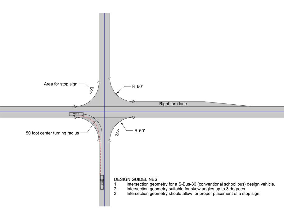
A simple curve is the easiest to design and construct; however, it does not match the turning path of a semi-truck, unless the turning path and simple curve are quite large. The large radius requires more right of way, results in unused pavement, and in urban areas, increases pedestrian crossing times. Thus, simple curves are used for intersections designed for vehicles other than semi-trucks. A simple curve design, however, should not restrict a semi-truck from turning at the intersection. The semi-truck should be still able to turn at the intersection by encroaching into an opposing lane if needed. See Section 6A-2 for guidance on vehicle paths and encroachment into opposing lanes.
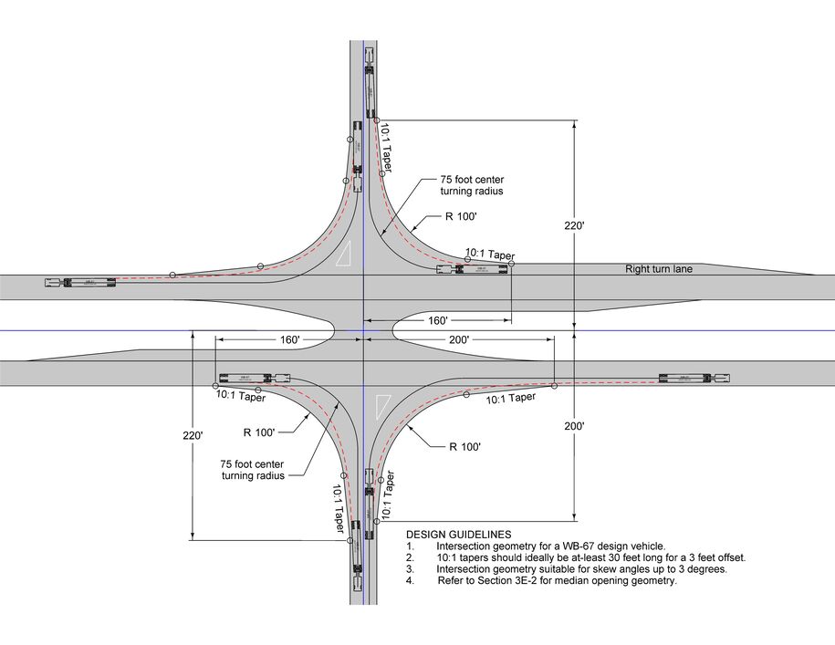
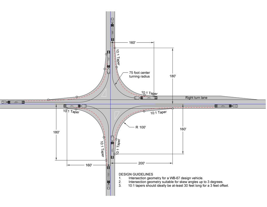
A compound curve arrangement (two-centered or three-centered curves) or simple curve with taper offsets provides a better fit to the turning path of a semi-truck. Either design is acceptable for intersections designed for turning semi-trucks.
Rural Intersections
Edge return geometry for rural intersections should consider right of way, placement of regulatory signs, utilities, intersection angle, and the frequency of turning buses and large trucks. Before designers begin to design a rural intersection, they should select a design vehicle, a turning path, and intersection control. The intersection geometry will affect locations of regulatory signs, such as a stop sign. For guidance on the proper placement stop signs or stop sign islands, refer to Section 6A-11.
Paved Intersection Examples
Figures 1 through 3 show edge return designs for rural intersections that intersect at nearly 90 degrees.
Non-Paved Intersection Examples
Design gravel roads intersecting state highway using a simple curve. A radius of 50 feet is adequate for intersections between state highways and granular roads. Refer to Design Details 7148 and 7149 for additional details.
Urban intersections
Edge return geometry for urban streets should consider right of way, placement of traffic signal poles, utilities, intersection angle, pedestrian traffic, and the frequency turning buses and large trucks. The following simple curve radii can be used as a guide for selecting a radius; however, site specific conditions ultimately decide the design:
- 15 to 25 foot radii are adequate for intersections designed for passenger vehicles.
- 25 to 35 foot radii are used on new construction where space permits.
- A radius of 40 feet or more with taper offsets is used at intersections which need to accommodate semi-trucks and busses. A compound curve arrangement is also acceptable.
Design Summary
Rural intersection design
- Select the design vehicle. Refer to Section 6A-2.
- Determine the turning movement. Refer to Section 6A-2.
- Select the type of edge return geometry, e.g., simple curve with taper offsets.
- Simulate the turning maneuvers using a CAD-based program, i.e. AutoTURN.
- Check the proposed design clearance against the generated vehicular wheel path.
- Check the design for turning semi-trucks. The intersection geometry should not restrict trucks for turning maneuvers.
- Consider where signs will be placed, e.g., stop signs.
- Consider available right or way and other impacts within the roadside, e.g. utilities.
- Revise the design as necessary to accommodate the turning movement.
Urban intersection design
- Select the design vehicle. Refer to Section 6A-2.
- Determine the turning movement. Refer to Section 6A-2.
- Select the type of turning geometry, e.g., simple curve.
- Simulate the turning maneuvers using a CAD-based program, i.e. AutoTURN.
- Check the proposed design clearance against the generated vehicular wheel path.
- Consider impacts to pedestrians and bicyclist.
- Check the design for turning semi-trucks. The intersection geometry should not restrict trucks for turning maneuvers.
- Consider where the traffic signal poles will be placed.
- Consider pavement surface drainage and locations of intakes.
- Consider available right or way and other impacts within the roadside, e.g. utilities.
- Revise the design as necessary to accommodate the turning movement.