
Content Information
On this page...
Background
The Mobility and Safety (Super-2) section of Chapter 5 in the State Transportation Plan (STP) states:
“As part of the 2017 plan, analysis was conducted to provide a data-driven recommendation for mobility and safety improvements to Primary Highway System corridors. The aim was for these improvements to enhance the operation of the network in particular corridors where capacity expansion needs were not identified, but improvements would help the corridors compliment the state’s multilane highway network.
The mobility and safety improvements are realized through the Super-2 concept. As part of the 1997 State Transportation Plan, the Iowa DOT introduced Super-2 style roadways with the basic goals of maximizing the benefits of two-lane roadways through improved roadway safety, capacity, and mobility, while reinforcing the growing importance of lowering right-of-way needs and construction and maintenance costs. Super-2 improvements serve as alternatives to four-lane capacity expansion projects and can aid in uninterrupted flow of traffic and the accommodation for slower traffic when necessary. A defining feature of Super-2 improvements is the addition of passing lanes, which improve roadway operation by providing opportunities to pass slower-moving vehicles. Other examples of Super-2 design elements include wider paved shoulders, left and right turn lanes, acceleration lanes, limited access, and geometric improvements.”
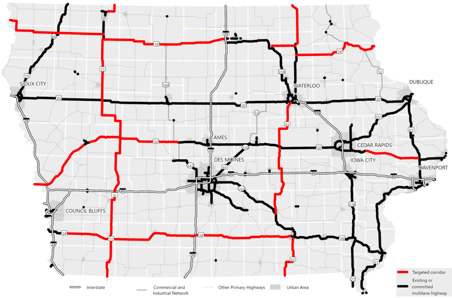
Chapter 5 of the STP also lists routes targeted for Super-2 enhancements, see Table 1 and Figure 1 below. Super-2 enhancements may be applied to other two lane corridors not identified in the STP.
This section provides design guidance related to passing lanes, turning lanes, access management, shoulder design, signs and pavement markings, and rumble strips for Super-2 Highways.
Back to topPassing Lanes
Super-2 highways provide improved safety and mobility on two lane roadways by providing passing opportunities for faster moving vehicles, thus reducing the potential for a head on crash with oncoming traffic. Passing opportunities are created by providing passing lanes at regular intervals. The length of passing lanes is adjusted depending on traffic volumes on the route. Since traffic volumes can vary within a corridor, passing lane spacings and lengths must be applied to individual segments of the corridor, rather than the whole corridor, to ensure proper operation of a Super-2 facility.
Passing Lane Location
When reviewing a corridor for passing lane locations, avoid the following locations if possible:
Areas of reduced speed adjacent to incorporated areas of municipalities.
Areas with six or more accesses per mile in one direction of travel.
Bridges or multiple barrels reinforced concrete box culverts to avoid the added expense of widening or lengthening existing structures.
At-grade railroad crossings.
Areas where the right-of-way (ROW) line is shared with a railroad, unless there is sufficient room within the existing ROW to accommodate the passing lane and not impact drainage.
Four-legged intersections with paved approaches on all four legs. Placing passing lanes through intersections with unpaved sideroads is acceptable, and in some instances will be necessary due to the passing lane length. If placing a passing lane through a paved intersection is unavoidable, contact the Geometrics Coordinator.
Horizontal curves with advisory speeds less than the posted speed limit of the roadway.
Curves with limited horizontal sight distance.
Environmentally sensitive areas.
Within one mile of the ramps at interchanges.
When determining passing lane locations, consideration needs to be given to passing lane locations for the opposing direction of traffic. Figure 2 shows different passing lane location configurations for opposing traffic lanes.
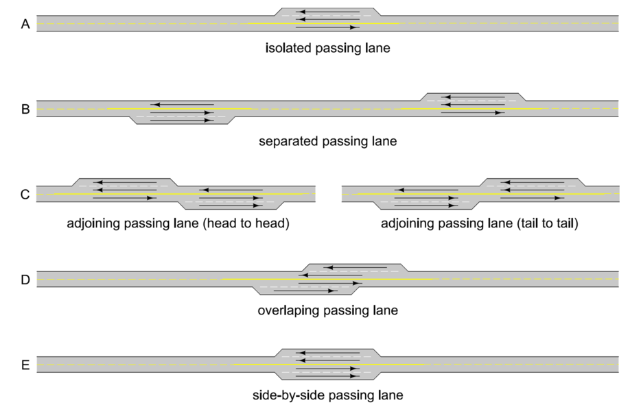
Configuration A is intended to be used where a passing opportunity is only needed in one location. Configuration B is the preferred pattern for the locations of the passing lanes. If adjustments for the passing lane locations are necessary, configuration C (either head to head or tail to tail) may be used. Of the two, tail to tail is preferred. Configuration D is typically the result of the passing lanes functioning as a combination passing/climbing lane or in areas where other constraints prevent offsetting the passing lanes. The use of Configuration E gives the appearance that the roadway in the area of the passing lane is a four lane undivided section, so it should only be used when constraints on the project prevent offsetting the passing lanes as shown on the other configurations.
In areas where hilly terrain exists, passing lanes should be placed on ascending grades to allow the passing lane to function as a combination passing lane/climbing lane.
Back to topPassing Lane Design
Typical Passing Lane Section
Twelve-foot-wide lanes are preferred. Eleven-foot-wide lanes are acceptable.
Passing Lane Spacing
Preferred spacing between passing lanes is 4 to 5 miles. This spacing is based on the desire to provide passing opportunities with uniform spacing between each passing opportunity in one direction. The length between passing lanes may adjusted up to 0.50 miles to avoid items in the list of features to avoid, or to avoid impacts to other features in the corridor (utilities, accesses, etc.). The absolute minimum distance between passing lanes is 3.5 miles.
Passing Lane Lengths
As Figure 3 shows, passing lanes are introduced using a diverge taper and are dropped using a merge taper. Figure 3 also shows reference locations for the distance between passing lanes.
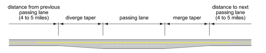
The diverge taper should be developed using a 15:1 taper rate. The length of the merge taper depends on the design speed of the roadway and should be based on the length of taper and taper rates for dropping lanes found in Section 6C-1.
The length of the passing lane is based on the current Average Annual Daily Traffic (AADT) or the current Vehicles Per Hour (VPH) volumes for the roadway and are shown in Table 2.
When a passing lane will also function as a climbing lane, the lengths shown in Table 2 should be extended to aid trucks in climbing the grade.
Back to topTurning Lanes
Left turn Lanes
Warrants for left turn lanes will be based on safety and volume. If either warrant is met, include left turn lanes.
Safety Warrants for Left Turn Lanes
The Potential for Crash Reduction (PCR) dashboard can be used to search for patterns of correctable crashes at intersections, e.g. rear-end, angle oncoming left turn, or sight distance related, that could be addressed with left turn lanes. Use the KAB filter to review High/Medium intersections.
Volume Warrants for Left Turn Lanes
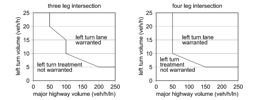
Figure 4 (based on NCHRP Report 745 Figure 2) is used to determine left turn warrants. Warrants are based on design year volumes.
Right Turn Lanes
Right turn lanes should be placed at all paved intersections and should be considered at unpaved intersections. Offset right turn lanes are preferred. Section 6C-5 provides guidance for offset right turn lanes. If a 20-foot offset is not possible due to ROW constraints, the maximum amount of offset should be provided given sight distance and available ROW. Refer to Section 6D-1 for information related to intersection sight distance.
Back to topAccess Management
Chapter 2 of the Access Management Manual provides information regarding classification of accesses and roadways (types and categories, respectively), which are used to determine required spacing. Chapter 3 of the Access Management Manual provides information regarding location and design of accesses.
Contained within Chapter 3 of the Access Management Manual is a discussion of functional area for an intersection. The functional area of an intersection is where movements such as slowing, stopping, turning, queuing, and complex traffic maneuvers may result in the potential for conflicts and crashes.
Passing lanes also have a functional area (though not defined in the Access Management Manual). It is the length of the passing lane plus the diverge and merge tapers (see Figure 2 above for passing lane components).
New accesses should not be located within the functional area of an intersection or passing lane. Existing accesses may remain if approved by the District Engineer. Relocation is preferred if it can be done at a reasonable cost. Frontage roads are not desired, but may be considered for extreme cases.
Outside of functional areas, accesses should be located at ¼ mile spacing.
Back to topShoulder Design
Shoulders at passing lanes shall be paved. Refer to Table 3 for shoulder widths. These widths apply throughout the Super-2 corridor.
*At parallel right turn lanes, shoulders may be reduced to 2 feet and safety edge is not required.
Designers are encouraged to use design flexibility to minimize the impact on right-of-way and construction when evaluating widening shoulders. Refer to Section 1C-8 for documenting design decisions.
Back to topSigns and Pavement Markings
Standard Road Plan PM-222 shows layouts for the necessary signing and pavement markings for passing lanes and intersections with passing lanes.
Back to topRumble Strips
Shoulder and centerline rumble strips should be carried through passing lanes. Refer to Section 3C-5 and PV-12 and PV-13 for more information regarding rumble strips.
Back to top